Table of Contents
Advertisement
Copyright
Our company owns all rights of this unpublished work and intends to maintain it as a
confidential work. We may also seek to maintain this work as an unpublished copyright. This
publication is to be used solely for the purpose of reference or operation of our device. No
part of this work can be disseminated for other purposes.
In the event of inadvertent or deliberate publication, we intend to enforce its rights to this work
under copyright laws as a published work. Those having access to this work may not copy,
use, or disclose the information in this work unless expressly authorized by our company.
All information contained in this publication is believed to be correct. We shall not be liable for
errors contained herein nor for incidental or consequential damages in connection with the
furnishing, performance, or use of this material. The information this publication refers to is
protected by copyrights or patents and does not convey any license under the patent rights
of our company, nor the rights of others. We do not assume any liability arising out of any
infringements of patents or other rights of third parties.
Content of the manual is subject to change without prior notice.
Model: HCSMD400
Version: Ver1.0
Revised Date: October 16, 2016
Advertisement
Table of Contents

Related Manuals for Medline HCSMD400


Summary of Contents for Medline HCSMD400
- Page 1 We do not assume any liability arising out of any infringements of patents or other rights of third parties. Content of the manual is subject to change without prior notice. Model: HCSMD400 Version: Ver1.0 Revised Date: October 16, 2016...
-
Page 2: Table Of Contents
Content 1 Introduction ....................1 1.1 Brief Introduction ........................1 1.2 Intended Use ........................1 1.3 Measurement Principle .......................1 1.4 Safety Information ......................1 1.5 Electromagnetism Interference ..................4 1.6 Explanation of Symbols ......................4 1.7 Product Features ........................5 1.8 Contraindication .........................5 2 General Description ..................6 2.1 Appearance ........................6 2.2 Power Supply ........................7 3 Take a Measurement ..................9... -
Page 3: Introduction
INSTRUCTION MANUAL 1 Introduction 1.1 Brief Introduction Thank you for purchasing the HCSMD400 pulse oximeter. The main functions of the device include SpO PR and PI (Pulse Amplitude Index) measurements, visual and audible alarm, data storage, review and transmission, etc. Please read this manual carefully before using the device. - Page 4 HCSMD400 PULSE OXIMETER Warnings! Before use, carefully read the manual. This device is intended for use by persons trained in professional health care. Our company will assume no warranty for using this equipment improperly. The pulse oximeter is to be operated by qualified personnel only.
- Page 5 HCSMD400 INSTRUCTION MANUAL to treat a patient, pay special attention to data cable and check it more frequently. Do not tangle the SpO cable with the wires of ES (Electrosurgery) equipment. Single use accessories should never be reused. Only use SpO sensors specified by the manufacturer.
-
Page 6: Electromagnetism Interference
HCSMD400 PULSE OXIMETER Venous pulsations; Placement of a sensor on an extremity with a blood pressure cuff, arterial catheter, or intravascular line; The patient has hypotension, severe vasoconstriction, severe anemia, or hypothermia; The patient is in cardiac arrest or is in shock;... -
Page 7: Product Features
HCSMD400 INSTRUCTION MANUAL Class II equipment Date of Manufacture Follow instructions for Pulse rate The waste electrical and Battery cover unlock / lock electronic equipment Adpater polarity Do not discard the device symbol and other components 1.7 Product Features High resolution 2.8” TFT screen display SpO , PR, and PI (Pulse Amplitude Index) waveform and pulse bar. -
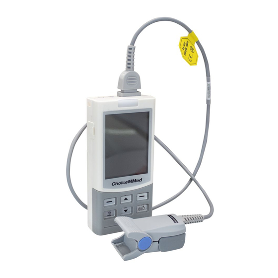
Page 8: General Description
PULSE OXIMETER 2 General Description The HCSMD400 pulse oximeter adopts 2.8 inch TFT screen, which can display the SpO pulse rate, Pulse Amplitude Index and other indication parameters, such as time, ID number, pulse amplitude bar and battery power status, alarm limits and the connections of probes, etc. -
Page 9: Power Supply
HCSMD400 INSTRUCTION MANUAL (9) Power switch: Press and hold it for 3 seconds to power the device on, and for about 4 seconds to turn the device off. (10) Charge indicating lamp: If the battery is full charged, the green light will appear. If the battery is less than 20% charged, a red light will flash. - Page 10 HCSMD400 PULSE OXIMETER If battery fluid gets on your skin or clothing, rinse with plenty of clean water immediately. Remove the batteries from this unit when you are not going to use it for a long period of time (approximately one month).
-
Page 11: Take A Measurement
HCSMD400 INSTRUCTION MANUAL 3 Take a Measurement 3.1 Probe Connection Insert the SpO probe to the socket, as shown in Fig.3-1. If the SpO probe is disconnected from the unit, “Probe Off” will appear in the status column. Fig.3-1 Notes:... -
Page 12: Factors That May Affect The Measurement
HCSMD400 PULSE OXIMETER Measuring 70 8.1 ID:001 Menu 12:00 Shift Fig.3-3 Wave display Fig.3-4 Digital display Description of measurement screens: 1. Measuring: The pulse oximeter is in the status of measuring. It shows “Finger off” when there is no finger inserted or no signal is detected. -
Page 13: Alarm
HCSMD400 INSTRUCTION MANUAL 5) carboxyhemoglobin 6) methemoglobin 7) methylene blue 8) Indigo carmine Do not use the SpO probe with exposed optical components. Tissue damage can be caused by incorrect application or use of probe, for example by wrapping the probe too tightly. Inspect the probe site to ensure skin integrity and correct positioning and adhesion of the probe. - Page 14 HCSMD400 PULSE OXIMETER Assignment of priority: High Paramter Value Alarm lamp Flashing Lamp Frequency 1.5Hz Audiblesound Di- Di – Di ----- Di - Di Alarm cycle 20 s Alarm info too high/low, Battery power low Probe off/Finger out Notes: 1. The alarm will appear if the measurement value out of range.
-
Page 15: Settings
HCSMD400 INSTRUCTION MANUAL 4 Settings Always set the date and time before using the unit for the first time. Set different ID numbers for different users. Check the date and time are correct before using the unit, and reset them if necessary. The date and time are important indicators when a measurement is taken. -
Page 16: User Id Setting
HCSMD400 PULSE OXIMETER value. The date is displayed as the order of Year-Month-Day and Time of Hour-Minute 4.2 User ID Setting Every time, when you insert your finger, the ID icon will flash about 5 seconds. If you press the OK button in 5 seconds, the ID number will not change, or else the ID number will ncrease after 5 seconds. -
Page 17: Data Management
HCSMD400 INSTRUCTION MANUAL 4.4 Data Management From the main menu screen, select and enter the “Data Manage” screen, refer to Fig.4-4. Measuring 120s Date Mangagement Data Review SpO2 Trend PR Trend Delete All Data 12:00 Back Fig.4-4 Press the Navigation button to select the sub-item to set, and then press the OK button to confirm or Back button to return to the previous screen. - Page 18 HCSMD400 PULSE OXIMETER 4.4.2 SpO Trend Pick and enter the “SpO Trend” interface as shown in Fig.4-6. By pressing the Navigation button to review the records page by page. Press the Back button, the pulse Oximeter returns to the previous interface.
-
Page 19: System Setting
HCSMD400 INSTRUCTION MANUAL Measuring 120s Deleted all data 12:00 Back Fig.4-8 4.5 System Setting Pick and enter the [System Setting] interface from the main menu. And then press the Navigation buttons to select different item to set. Measuring 120s Measuring... -
Page 20: Data Transmission
HCSMD400 PULSE OXIMETER 5 Data Transmission Measuring 120s Use USB cable to transmit the measurements to PC for further review and analyze. Before data transmission, make sure to turn the device on and connect it with a computer by the attached USB cable. The operations refer to the User Manual of the data transmission Software. -
Page 21: Maintain And Repair
HCSMD400 INSTRUCTION MANUAL 6 Maintain and Repair Warnings! The advanced circuit inside the oximeter does not require periodic calibration and maintenance, except replacing the batteries. Don’t open the cover of oximeter or repair electronic circuits. Its open will cause the damage of the device and the annulment of the guarantee. -
Page 22: Calibrating
HCSMD400 PULSE OXIMETER 6.3 Calibrating A functional tester cannot be used to assess the accuracy of a pulse oximeter monitor or sensor. Clinical testing is used to establish the SpO accuracy. The measured arterial hemoglobin saturation value (SpO ) of the sensors is compared to arterial hemoglobin oxygen (SaO ) value, determined from blood samples with a laboratory CO-oximeter. - Page 23 HCSMD400 INSTRUCTION MANUAL installed or connected with the external devices which are not permitted by Our company, e.g. printer, computer, cable and lead to oximeter failure. Our company will charge for the maintenance. d) Responsibility limitation During the period of warranty, if user changes the parts manufactured by the third party without our company permission, our company is entitled to stop contract.
-
Page 24: Appendix A Specifications
HCSMD400 PULSE OXIMETER APPENDIX A Specifications Notes: ● Specifications may be changed without prior notice. ● The circuit diagrams, the list of components, the illustration of diagrams, and the detailed rules of calibration, are provided exclusively to professional personnel authorized by our company. - Page 25 HCSMD400 INSTRUCTION MANUAL Probe Emitter: OL660905HM2-2(H2)-C Receiver: OP30TMF-3 Probe LED Specifications: Wavelength Radiant Power 660±3nm 3.2mW 905±10nm 2.4mW Environment Requirements Operation temperature: 0℃~40℃ Operation humidity: ≤80%,no condensation Storage / transport temperature: -20℃~+70℃ Storage / transport humidity: ≤93%, no condensation Power supply: Three AA alkaline batteries, rechargeable batteries or adapter Working time: alkaline batteries: more than 10 hours;...
- Page 26 HCSMD400 PULSE OXIMETER Equipment Classification Classification according to IEC-60601-1 According to the type of protection against Internal electrical power source equipment Electrical shock and Class II equipment According to the degree of protection against Type BF equipment Electrical shock According to the degree of protection against IPX1 harmful ingress of water.
-
Page 27: Appendix B Clinical Study Summary
The following details are provided to disclose actual performance observed in the clinical validation study of healthy adult volunteers. The ARMS value analysis statement and Bland- Altman plot of data for HCSMD400 and its supporting probes are shown as following: B.1 Clinical study details of HCSMD400 Pulse Oximeter and its supporting... - Page 28 HCSMD400 PULSE OXIMETER Bland-Altman Plot Graphic B.3 Clinical study details of HCSMD400 Pulse Oximeter and its supporting M-50J033CS045 Oximeter probe Table 6-3 ARMS Value Analysis Statement Item 90--100 80--<90 70--<80 #pts Bias -0.51 -0.41 1.56 1.34 1.49 2.36 Bland-Altman Plot Graphic...
-
Page 29: Appendix C Statement Of Manufacturer
Guidance and manufacturer’s declaration- electromagnetic immunity The model HCSMD400 Pulse Oximeter is intended for use in the electromagnetic environment specified below. The customer or the user of the model HCSMD400 Pulse Oximeter should assure that it is used in such an environment. - Page 30 Guidance and manufacturer’s declaration – electromagnetic immunity The model HCSMD400 Pulse Oximeter is intended for use in the electromagnetic specified below. The customer of the user of the HCSMD400 Pulse Oximeter should assure that it is used in such an environment.
- Page 31 INSTRUCTION MANUAL Portable and mobile RF communications equipment should be used no closer to any part of the model HCSMD400 Pulse Oximeter, including cables, than the recommended separation distance calculated from the equation applicable to the frequency of the transmitter.
- Page 32 To assess the electromagnetic environment due to fixed RF transmitters, an electromagnetic site survey should be considered. If the measured field strength in the location in which the model HCSMD400 Pulse Oximeter is used exceeds the applicable RF compliance level above, the Pulse Oximeter should be observed to verify normal operation.
- Page 33 HCSMD400 INSTRUCTION MANUAL For transmitters rated at a maximum output power not listed above, the recommended separation distance in meters (m) can be estimated using the equation applicable to the frequency of the transmitter, where P is the maximum output power rating of the transmitter in watts (W) according to the transmitter manufacturer.
Need help?
Do you have a question about the HCSMD400 and is the answer not in the manual?
Questions and answers