Table of Contents
Advertisement
Advertisement
Table of Contents

Subscribe to Our Youtube Channel
Related Manuals for Okolab H201-T-UNIT-BL

Summary of Contents for Okolab H201-T-UNIT-BL
- Page 1 H201-T-UNIT-BL Temperature Control Unit Manual IST1254_REV01 3.5.4.3048...
-
Page 2: Table Of Contents
SAFETY NOTES ..................................5 SUPPLIED EQUIPMENT ................................7 NOT SUPPLIED EQUIPMENT ..............................7 ....................................8 PTIONAL QUIPMENT EQUIPMENT DESCRIPTION ..............................9 INSTALLATION ..................................11 H201-T-UNIT-BL. I ............................11 NSTALLATION GUIDE H201-T-UNIT-BL BOLD LINE D ............. 13 OW TO CONNECT TO A... -
Page 3: Preface
The system is composed of the enclosure surrounding the microscope, H201-ENCLOSURE, which design depends on the user’s microscope, the Temperature Control Unit, H201-T-UNIT-BL with the Heating Box, the HM- VF composed by a humidity module and a water trap (purchased separately) -
Page 4: Symbol Description
Symbol description This paragraph describes the symbols used in the manual and on the product label. Symbols used in this manual The following symbols identify important information to note: CAUTION or WARNING: this symbol warns you about the risk of electrical shock. CAUTION or WARNING or IMPORTANT: this symbol warns you of circumstances or practices that can affect the functionality of the instrument. -
Page 5: Safety Notes
Safety Notes In order to achieve maximum performance and to ensure proper operation of your new equipment, please read carefully the following safety notes and the instructions. If you have any question, please contact Okolab. − The equipment must only be used as intended and as described in this Manual. - Page 6 We reserve the right to make technical variations. IN NO EVENT SHALL OKOLAB S.R.L. BE LIABLE FOR ANY DIRECT, INCIDENTAL OR CONSEQUENTIAL DAMAGES OF ANY NATURE, OR LOSSES OR EXPENSES RESULTING FROM ANY DEFECTIVE PRODUCT OR THE USE...
-
Page 7: Supplied Equipment
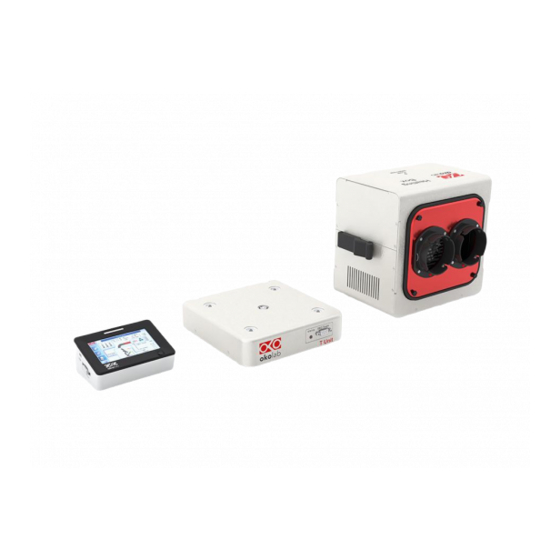
4. NTC Thermistor (pointer 4 in Figure 1). To measure ambient temperature 5. #1 24V-DC Power Adapter (pointer 5 in Figure 1). To connect the Temperature Control Unit Figure 1. H201-T-UNIT-BL equipment overview. NOT supplied equipment H201-T-UNIT-BL can be equipped with: 1. -
Page 8: Optional Equipment
Figure 57 and Figure 58). 6. Power supply cable. To connect the Heating Box. 7. Okolab incubating chamber (see pointer 12 in Figure 1) with lid and base, chamber riser with one or more plate adapters. 8. OKO-TOUCH (see point 13 in Figure 1), including: −... -
Page 9: Equipment Description
SM-BL Smart Box. To store data, to operate the controllers via web/smartphone/tablet and to allow remote assistance for service. Equipment Description A detailed description of the H201-T-UNIT-BL rear is provided in the following list, which refers to the pointers in Figure 5: 1. OKO-TOUCH RS232 serial port. - Page 10 8. Gauge Thermocouple port. Figure 5. Control Unit Overview...
-
Page 11: Installation
Sensor cable Electrical Connection Heating Box Figure 6. H201-T-UNIT-BL. Standard Connection 1. Connect the Heating Box to the port labeled ‘Heating Box’ on the rear panel of the Temperature Control Unit (see Figure 6). 2. Plug the NTC Connector on the port labeled ‘Ambient Temperature’ located on the rear panel of the Temperature Control Unit (see Figure 6). - Page 12 6. Connect the 24V-DC Power adapter to the Temperature Control Unit. 7. To switch H201-T-UNIT-BL on use the power button on OKO-TOUCH (see Figure 11). A small green LED light will blink on the front of the Temperature Control Unit. This means that the system is initializing.
-
Page 13: How To Connect H201-T-Unit-Bl To Abold Line Digital Gas Controller
How to connect H201-T-UNIT-BL to a BOLD LINE Digital Gas Controller H201-T-UNIT-BL can be used as a stand-alone device or in combination with any one of the Bold Line Gas Controllers. Figure 8 shows how to assemble H201-T UNIT-BL, for example, with a CO2-O2 Unit BL [0-10; 1-18]. -
Page 14: User Interface
8. Settings. Press here to access system options and settings 9. Home. To open the homepage 10. Product info. Press here to know generic info about OKO TOUCH and H201-T-UNIT-BL and running time Tip ► The Touch Screen is pre-set at the following temperature: 37°C. Once turning the Touch Screen on it will start operating to reach this set-point value. -
Page 15: Controller Status: Colours Led And Meaning
The system is working properly, it is not in alarm and no action is needed. As soon as the H201-T-UNIT-BL stabilizes the temperature, the Controller Status changes to NORMAL and the color turn GREEN. If the H201- T-UNIT-BL cannot stabilize the temperature of one or both heating devices within the maximum time defined by the operator (see paragraph 8.2.2.5), the Controller Status changes to ALARM... -
Page 16: Settings
Top LED Power Button Figure 11. Top LED and Power Button. Settings 8.2.1 Temperature To choose and insert the proper operation parameters, follow the instruction below: 1. Press on the Settings icon (see Figure 12 a) to enter the Settings menu. 2. -
Page 17: Control Mode
8.2.1.1 Control Mode The Temperature Control can run in two different modes: Sample or Cage Feedback Mode. Press on Control Mode icon (see Figure 14 a) to choose which one you want to use, Sample or Cage Feedback Mode. Figure 14 b shows how to select Cage Feedback Mode. Figure 14. - Page 18 Figure 16. Free Sensor attached on the internal base of the Petri Dish Tip ► It is recommended using an Okolab SENSOR LID (available for purchase) to secure the Fine Gauge Thermocouple in place in the Reference Well during calibration or operation in Sample Feedback Mode (see Figure 17).
-
Page 19: Fan Speed
Figure 17. SENSOR LID-35. For 35 mm Petri-dish Tip ► Advantages of Sample Feedback Control Mode are: direct monitoring and active control of sample temperature and independence from room temperature variations. The disadvantage is that it requires manual operation for correct placement of the fine gauge thermocouple in a Reference Well. 8.2.1.2 Fan Speed The Heating Box has an internal flow sensor that allows regulating the speed of the Air being blown inside... -
Page 20: Air Filters
If you have purchased also H201-T-FILTER-BOX, a module containing a filters kit composed by a prefilter and a HEPA filter (High Efficiency Particulate Air Filter) has been added to the Heating Box, see Figure 20. In this case, Okolab recommends activating the ‘Filter Monitoring’ in the Air Filters subpage. Press on Air Filters icon (see Figure 21 a), then active “Filter Monitoring”... - Page 21 When you active the ‘Filter Monitoring’, the counting of the usage days (indicated with ‘Update Time’) starts. The maximum usage time for the Prefilter is 180 days, while for the Hepa Filter is 360 days. When the usage time exceeds these values, the warning icons appear in the ‘Homepage’ and in the ‘Overview’: icon A in Figure 22 for HEPA filter, icon B in Figure 23 for Prefilter.
-
Page 22: Status
(see Figure 27 b). On this page you can see the status of the Temperature Control Unit, with a summary of all parameters allowing you to check that all is working properly. You may have to refer to this window when asking for Okolab technical support. Figure 27. Status page (a – b) -
Page 23: Calibration
8.2.1.5 Calibration For maximum of accuracy when using “Cage Feedback Mode”, H201-T-UNIT-BL allows to calibrate the system in your lab at your Room Temperature. To do so, read the paragraph 9 and then follow the instruction below: 1. Press on the Calibration icon (see Figure 28 a) 2. -
Page 24: Touch Screen
Figure 30. Digital input ( a- b) 8.2.2 Touch Screen Press on the Settings icon (see Figure 31 a), then press on the Touch Screen icon (see Figure 31 b) to access to touch screen settings. Figure 31. Touch screen settings (a- b) 8.2.2.1 Options Press on the Options icon... -
Page 25: Brightness
Never, the Top LED will never illuminate, if you select On Alarm, the Top LED will illuminate only when the H201-T-UNIT-BL is in Alarm Status (see paragraph 8.1.2), if you select Always, the Top LED will always illuminate. 8.2.2.4 Date &... -
Page 26: Alarms
Figure 35. Touch screen settings. Date and Time (a – b) 8.2.2.5 Alarms Press on the Alarms icon as shown in Figure 36 a. Then press on the Temperature icon (see Figure 36 b). Figure 36. How to enter in Alarms page (a – b). Tip ►Flag “Buzzer”... -
Page 27: Data Logging
8.2.2.6 Data Logging H201-T-UNIT-BL touch screen interface, OKO-TOUCH (see Figure 2), is equipped with on-board memory for data logging and storage. A simple routine allows downloading data to USB drive or to PC. In order to log and then download the logged data, connect a USB drive (not supplied) to OKO-TOUCH, using MINI-USB-OTG cable (provided), as shown in Figure 38. - Page 28 Tip ► When activating the logging on the internal memory, you can access the Logging page also by pressing the activated logging icon on the Homepage, as shown in Figure 41 Figure 40. Logging. (a) How to enter in the logging menu; (b) logging in internal memory Figure 41.
- Page 29 5. Write the file name suffix to be reported in the downloaded files by pressing on the keyboard icon , see Figure 43 a. Then press Save, see Figure 43 b. Tip ►With the selections as in Figure 42 and in Figure 43, the data will be downloaded on the USB drive as shown in Figure 44.
- Page 30 Figure 46. Download to USB You can activate the logging also on the USB drive, by flagging on USB drive, see Figure 47(a). Figure 47. Logging on USB flash drive. (a) USB drive selection; (b) Reminder to connect the USB drive In this case, OKO-TOUCH warns you that a USB drive must be connected to the USB port, see Figure 47(b), and will store the data on the USB drive.
-
Page 31: Overview
Figure 50. Display modalities: Icon Mode (a); Glance Mode (b). Info page Press on the icon to access the Info Page, as shown in Figure 51. This page contains the information related to the OKO-TOUCH and to the H201-T-UNIT-BL version (as shown in Figure 52 a and b). -
Page 32: Calibration
Figure 51. Info page selection Figure 52. Info page OKO-Touch and H201-T-UNIT-BL (a – b). Tip ►Please have this information handy when contacting Okolab for support Calibration Cage-Calibration Carefully read the instructions given in this paragraph before starting the Cage Calibration. - Page 33 You can also use SENSOR LID-# to close the dish (see the “Tip” below). Tip ► It is recommended using an Okolab SENSOR LID (available for purchase) to secure the Fine Gauge Thermocouple in place in the Reference Well during calibration or operation in Sample Feedback Mode (see Figure 17 and Table 1).
-
Page 34: Enclosure Standard Components
Enclosure standard components H201-T-UNIT-BL includes the enclosure (cage) surrounding the microscope (purchased separately). The enclosure depends on the user’s microscope therefore it can be different for each microscope. There are some parts of the enclosure that are, however, the same for all. The standard parts are shown in the following images. - Page 35 Figure 55. Water Trap inserting in the appropriate slot Tip ►This component allows recovering the condensation water (HM-VF) or the water accumulated into the permeable membrane tube (for HM-VF) in order to prevent the water reaches the chamber incubator. For example, in the case of HM-VF, when you switch your gas mixer off, the gas stops flowing through the permeable water membrane for a little time but the membrane continues to permeate the water and its little tube fills.
- Page 36 Connection with the Heating Box. Insert the hose bayonet connector ring that is on the end part of the tubes (TUBE J) on the hose bayonet connector flange mounted on the blue side of the Heating Box. Then rotate the bayonet connector ring until the screws do not fit into their housings.
- Page 37 Figure 61. Insert the black hose. Okolab suggests to cut the tubes in order to save space especially when: 1. the Heating Box is put on the same desk of the enclosure, very close to the enclosure (see Figure 62 for Configuration A).
- Page 38 Figure 62. Before vs after cutting the tubes – Configuration A (a -b). 2. the Heating Box is put on a shelf placed just above the enclosure (see Figure 63 for Configuration B). Figure 63 a shows configuration where tubes have not been cutting. Figure 63 b shows the space-saving after cutting the tubes.
- Page 39 Figure 64. Configuration C – Configuration D (a -b). D. Chamber Incubator insertion inside the enclosure. You can insert the chamber incubator on the stage before mounting the frontal panel or after have mounted the frontal panel simply opening the slide door on the left or on the right panel of the enclosure.
- Page 40 TUBE G TUBE I TUBE H Figure 66. Tubing connection inside the Enclosure with HM-VF. F. HM-ACTIVE tubing connection inside the Enclosure. If you have purchased also a digital gas mixer including HM-ACTIVE as humidity module, you have to connect the heated tube of HM-ACTIVE to the Chamber Incubator.
- Page 41 G. On the all Okolab enclosures there are some standard components which allow simplifying the layout of cables and pipes in your experimental environment. The Figure 68 shows for example an opening that you can find on the back panels, Image 2, useful for the passage of the electrical cables of the microscope or of the other components that you use for your experimental apparatus.
-
Page 42: Cleaning & Maintenance
To polish the Stage Incubator and the Humidifying Module, if it is present, you can use distilled water or alcohol − Verify the status of all cables and if some cable is damaged, contact Okolab to receive assistance Before cleaning the unit, pull out the mains plug. -
Page 43: Filters Replacement
3. If some halos are present on the piece (this may be the case of Acrylic), spray the Disinfectant again and immediately remove it gently with the Wipe. Note ► Please contact Okolab if you need further information about which Disinfectant and Wipe to use. Filters Replacement... - Page 44 HEPA FILTER PREFILTER Figure 69. Filters Replacement After replacing one or both the filters, do not dispose it/them as urban solid waste. The filters must be treated as special waste.
-
Page 45: Support
Support In order to send directly an email to the Okolab staff, you can use the QR codes shown in the following images: • • For commercial info: For technical info: Figure 70. QR code for commercial info contact Figure 71.QR code for technical info contact To contact one of our engineers please see below, write to support@oko-lab.com... -
Page 46: Technical Specifications
Technical Specifications H201-T-UNIT-BL - Technical Specifications Cage Temperature Range: 25-50°C Temperature Sample Temperature range: 3°C above ambient temperature to 45°C Step size: 0.1°C Accuracy:0.2°C in Sample Mode and in Cage Mode if room temperature remains within ± 1°C Regime temperature time... -
Page 47: Troubleshooting
Troubleshooting We have collected in the table below some frequently asked questions, please contact Okolab if you need support. Symptom Probable cause Remedy Supply cable disconnected Properly connect the cable Device off Supply cable damaged Substitute the cable Thermocouple cable disconnected... - Page 48 Figure 7.OKO-TOUCH Connection ......................................12 Figure 8. CO2-O2 UNIT-BL [0-10; 1-18] and H201-T-UNIT-BL ........................... 13 Figure 9. Homepage of the H201-T-UNIT-BL Controller Touch Screen Display ....................14 Figure 10. How to change the Temperature set point (a – b) ............................15 Figure 11.
-
Page 49: Manual Revision Table
Figure 66. Tubing connection inside the Enclosure with HM-VF..........................40 Figure 67. Tubing connection inside the Enclosure with HM-ACTIVE ........................40 Figure 68. Standard components on the enclosure panels............................41 Figure 69. Filters Replacement ........................................44 Figure 70. QR code for commercial info contact ................................. 45 Figure 71.QR code for technical info contact .................................. - Page 50 LIMITATION OF LIABILITY: the total liability of Okolab S.r.l. shall not exceed the purchase price of the component upon which liability is based. In NO event shall Okolab S.r.l. be liable for consequential, incidental or special damage.
Need help?
Do you have a question about the H201-T-UNIT-BL and is the answer not in the manual?
Questions and answers