Table of Contents
Advertisement
Quick Links
Advertisement
Table of Contents

Related Manuals for Spectron FS4


Summary of Contents for Spectron FS4
- Page 1 User manual Controller 05/2020...
-
Page 2: Table Of Contents
Table of contents Spectron Gas Control Systems GmbH Table of contents 1 Introduction..............................2 Description..............................2.1 Intended use ............................2.2 Misuse ..............................2.3 Identification / label ..........................2.4 Environment............................2.4.1 Temperatures..........................2.4.2 Degree of cleanliness ........................ 2.5 Standards and laws .......................... - Page 3 Spectron Gas Control Systems GmbH Table of contents 7.5.1 Recovery function ........................39 7.6 Manual mode ............................40 7.7 Alarm history............................43 7.8 Decommissioning ..........................43 8 Maintenance, cleaning and repairs......................44 8.1 General information on maintenance....................44 8.2 Regular maintenance work and cleaning....................45 9 Repair ................................
-
Page 4: Introduction
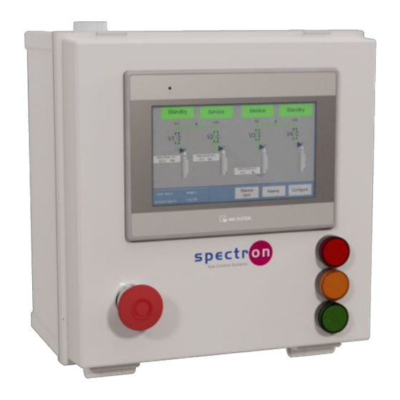
Spectron Gas Control Systems GmbH 1 Introduction This user manual is the original user manual for the Controller FS4 from Spectron Gas Control Systems GmbH (Fritz-Klatte-Str. 8, D-65933 Frankfurt), referred to as Spectron. The Controller FS4 constitutes an incomplete machine in the context of the Low Voltage Direct- ive 2014/35/EU. -
Page 5: Description
2 Description 2.1 Intended use The intended use of the Controller FS4 is the control of up to 4 pneumatic valves. These can be individually configured or used for up to 2 automatic changeovers between 2 gas sources each. The permissible gas types and pressure ranges are each specified on the label (see "Identifica- tion / label"). -
Page 6: Degree Of Cleanliness
2 | Description Spectron Gas Control Systems GmbH 2.4.2 Degree of cleanliness Access to the system and to the escape and rescue routes must not be blocked. The product should be kept clean (dust-free). For the control air, compressed air must be used of at least class 5 according to ISO 8573-1 or nitrogen (minimum quality 6.0). -
Page 7: Safety
Spectron Gas Control Systems GmbH Safety | 3 3 Safety 3.1 Basic information on the safety instructions The product complies with the recognised technical regulations. Nevertheless, knowledge of the media used and their dangers as well as basic knowledge of the pressure control panel are pre- requisites for safe and accident-free operation. -
Page 8: Safety Instructions
3 | Safety Spectron Gas Control Systems GmbH 3.2 Safety instructions DANGER Voltage The components of the control and the connections are under voltage. There is a danger of death on contact. a) Only allow work in which the control unit must be opened to be carried out by trained spe- cialist personnel (electricians). - Page 9 Spectron Gas Control Systems GmbH Safety | 3 WARNING Displacement of atmospheric oxygen In the event of inert gas leaks, displacement of atmospheric oxygen may occur. Danger of suf- focation! a) The operator must ensure adequate ventilation and airing in all rooms with gas installations and monitor the oxygen content.
-
Page 10: Emergencies And Safety Devices
3 | Safety Spectron Gas Control Systems GmbH CAUTION Static discharge Static discharges can occur in the event of contact between the control unit and persons or between parts of the electrical equipment. Injuries, shock responses and damage to the control unit are possible. - Page 11 Spectron Gas Control Systems GmbH Safety | 3 – Safety data sheets on the process gas used – Personal protective equipment In addition, operators must have the requisite physical and mental skills to operate and maintain the equipment. Persons who do not meet this requirement (e.g. visitors), must not remain alone in the overall system.
-
Page 12: Design And Function
For the operating firm, there are 10 digital inputs (NC or NC contacts) as well as 8 analogue in- puts (4-20mA) available for the FS4 controller. There is also a voltage-free relay output for re- porting the valve status. The connection to all input and output devices is established via cable glands on the underside of the body. -
Page 13: Functional Description
24V connection 4.2 Functional description The intended use of the Controller FS4 is the control of up to 4 pneumatic valves. These can be individually configured or used for up to 2 automatic changeovers between 2 gas sources each. The control unit is designed to allow 3 different programs to be selected by the user: The first program is intended for 2 independent gas supply systems, each of which has 2 gas sources, which switch automatically when one side is empty. -
Page 14: Technical Data
The following areas and functions have not been included in the scope of supply from Spectron: – other systems, lines and installations of the overall system –... -
Page 15: Installation
Spectron Gas Control Systems GmbH Installation | 5 5 Installation 5.1 General information CAUTION Injury or damage in the event of incorrect assembly or disassembly Special steps are required for assembly and disassembly work on the product. Personal injuries and damage to the product are possible. -
Page 16: Digital Inputs
5 | Installation Spectron Gas Control Systems GmbH 5.2.1 Digital inputs Illustration 1: Digital inputs The digital input module (P1-16ND3) provides the connections for the digital sensor inputs. Di- gital inputs of sensors and switches are directly connected to the terminals of the digital PLC in- put module. -
Page 17: Analogue Inputs
Spectron Gas Control Systems GmbH Installation | 5 5.2.2 Analogue inputs Illustration 3: Analogue inputs and safety clip The connections for the analogue inputs are connected directly to the module P1-08ADL-1. The negative terminal of each analogue signal generator is connected to one of the I+-terminals of the module. -
Page 18: Pneumatic Connection
5 | Installation Spectron Gas Control Systems GmbH C1 and relay outputs 1 to 8 are used by the controller and must not be otherwise assigned. C1 is disconnected from the network as soon as an emergency stop or remote shutdown signal is active. - Page 19 Spectron Gas Control Systems GmbH Installation | 5 WARNING Cross-contamination Cross-contamination of the control air with process gases can result in the control unit being damaged. a) Ensure that cross-contamination of the control air line is prevented. The solenoid valves require a supply of clean dry air or nitrogen filtered to 10μm, at max. 5.5 bar.
-
Page 20: Commissioning
6 | Commissioning Spectron Gas Control Systems GmbH 6 Commissioning 6.1 Preparations for commissioning The controller may only be commissioned following installation at the place of use and connec- tion of the control air and the electrical power supply. The power supply and the electrical connections inside the housing must be checked before commissioning. -
Page 21: Operation
Spectron Gas Control Systems GmbH Operation | 7 7 Operation 7.1 General information on operation All controller actions which require an input from an operator are protected by a dual layer pass- word system that allows up to five trained operators to have different operational access via their own personal Identification Number (PIN). - Page 22 7 | Operation Spectron Gas Control Systems GmbH After the system has been adapted to the user's requirements, these values are stored in bat- tery-buffered memories. When the device is switched on again, it is restarted with the custom user settings.
-
Page 23: Language Options
Spectron Gas Control Systems GmbH Operation | 7 If a valid password has been entered, the login window displays the username and access level for that password. Pressing "Log out" logs out the user and removes the associated system ac- cess rights. -
Page 24: User Management
7 | Operation Spectron Gas Control Systems GmbH 7.2.2 User management Press "Administration" to manage names, passwords, and access levels. Pressing the name or password displays a keyboard for data entry. A maximum of 16 charac- ters for the long name can be entered for each user. PIN numbers from 0001 to 9999 can be entered as passwords. -
Page 25: System Configuration
Spectron Gas Control Systems GmbH Operation | 7 7.2.3 System configuration Press "System Configuration" to configure the system. Three different system configurations are available: – 2 systems with automatic changeover – 1 Automatic changeover (valves 1 and 2) and 2 independent valves (valves 3 and 4) –... - Page 26 7 | Operation Spectron Gas Control Systems GmbH To change the logic of the changeover overlap, press the logic icon. This switches between the two available overlap options (both valves open / both valves closed). Overlap time (both sides closed for 2 seconds): If individual valves are enabled, they can be disabled by pressing "Enabled".
-
Page 27: Real Time Clock
Spectron Gas Control Systems GmbH Operation | 7 7.2.4 Real Time Clock The real-time clock can be accessed via the configuration menu. The real-time clock ensures that all displayed error states are marked with the correct date and time. The time is set via this screen:... -
Page 28: Analogue Inputs
7 | Operation Spectron Gas Control Systems GmbH 7.2.5 Analogue inputs Press the name of an analogue input to change it. "min" is used to select the minimum sensor value. Selecting "min"= – "-1" automatically sets the pressure unit [bar] –... - Page 29 Spectron Gas Control Systems GmbH Operation | 7 If there are inputs that are configured as weight (kg or lbs), the "Tare setting [} 34]" menu is used to automatically add an input field for the tare weight value. The current values of the analogue inputs are displayed as soon as the unit and the measuring range are entered.
- Page 30 7 | Operation Spectron Gas Control Systems GmbH Press "No action" to scroll to the required alarm action. These are the possible settings for alarm actions: Action Description No action The alarm is not active Warning The alarm is active but does not switch any valves...
-
Page 31: Digital Inputs
Spectron Gas Control Systems GmbH Operation | 7 7.2.6 Digital inputs Press the name of a digital input to change it. The status (normally open NO or normally closed NC), as well as the desired delay can be set. Pressing "Next" will take you to the digital alarm configuration. - Page 32 7 | Operation Spectron Gas Control Systems GmbH Pressing "Next" will then open the list of alarm names. You can assign different alarm actions to these alarm names. Press "No action" to scroll to the required alarm action. These are the possible settings for alarm actions: see analogue inputs The settings of the first 3 digital inputs have been configured on the following screen so that all valves are closed in an alarm situation.
-
Page 33: Label Valves
Spectron Gas Control Systems GmbH Operation | 7 Pressing OK will take you back to the configuration menu. 7.2.7 Label valves Pressing "Label Valves" in the configuration menu to change the names of the valves in the de- fault overview. -
Page 34: Tare Setting
7 | Operation Spectron Gas Control Systems GmbH "Display scale" automatically adds a cylinder scale symbol in the default overview if an ana- logue value is assigned to it. For this reason, this value should also come from a scale. -
Page 35: Commissioning A Valve
Spectron Gas Control Systems GmbH Operation | 7 If you have entered a tare weight, the weight of the cylinder content is output as a display value. This value is used to trigger alarm actions. 7.3 Commissioning a valve If all valves are closed and there are no active errors, the valve status is displayed as "Out of service". -
Page 36: Putting The Valve In Standby Mode
7 | Operation Spectron Gas Control Systems GmbH Press the "Enabled" button to commission the valve. 7.4 Putting the valve in standby mode If you click the "Out of service" status display for valve 2 (V1R) during an automatic changeover after commissioning the 1st valve, a selection window is displayed. -
Page 37: Automatic Switchover
Spectron Gas Control Systems GmbH Operation | 7 Press the "Enabled" button. As valve 1 is already in operation, valve 2 is put into standby mode. 7.5 Automatic switchover On the following screen, the cylinder on valve V1L has triggered an alarm because the set cylin- der pressure is has not reached the setpoint value. - Page 38 7 | Operation Spectron Gas Control Systems GmbH When an alarm is triggered, the date and time as well as the name of the alarm are recorded. The entries of the resolved alarms must be cancelled to be able to resume operation. They can only be cancelled if access is enabled with a level 1 or 2 password.
-
Page 39: Recovery Function
Spectron Gas Control Systems GmbH Operation | 7 If the error has not been rectified and the right side has also fallen below the set cylinder pres- sure, the right side remains in operation. All alarms are stored in the alarm history and can be retrieved via the configuration menu. Each alarm is automatically cleared from the history after 3 months. -
Page 40: Manual Mode
7 | Operation Spectron Gas Control Systems GmbH Pressing "Recovery" takes you to the selection menu for the recovery function. Here you can activate and set the recovery function for the respective automatic changeover: Switch on the recovery function for the system for which it is to be activated. - Page 41 Spectron Gas Control Systems GmbH Operation | 7 This state differs from the operating mode in that the valves can also be opened in the event of an alarm. Only the signals for emergency shutdown and remote shutdown have priority over manual oper- ation.
- Page 42 7 | Operation Spectron Gas Control Systems GmbH Selecting "YES" will open the valve. If you touch the opened valve, then you can close it again. GES_FS4_0520...
-
Page 43: Alarm History
Spectron Gas Control Systems GmbH Operation | 7 7.7 Alarm history The configuration menu is used to access the "Alarm history". All generated alarms are displayed there. The alarms already rectified are marked in green. Each alarm is stored for 3 months and then deleted automatically. -
Page 44: Maintenance, Cleaning And Repairs
8 | Maintenance, cleaning and repairs Spectron Gas Control Systems GmbH 8 Maintenance, cleaning and repairs 8.1 General information on maintenance DANGER Voltage The components of the control and the connections are under voltage. There is a danger of death on contact. -
Page 45: Regular Maintenance Work And Cleaning
Spectron Gas Control Systems GmbH Maintenance, cleaning and repairs | 8 Before beginning maintenance work, the controller must be enabled and secured against recon- nection. Observe the five safety rules according to DIN VDE 0105: – Disconnect from the mains –... -
Page 46: Repair
9 | Repair Spectron Gas Control Systems GmbH 9 Repair 9.1 General information on repair work DANGER Voltage The components of the control and the connections are under voltage. There is a danger of death on contact. a) Only allow work in which the control unit must be opened to be carried out by trained spe- cialist personnel (electricians). -
Page 47: Troubleshooting And Fault Rectification
Spectron Gas Control Systems GmbH Repair | 9 – Carry out earthing and short circuiting – Provide protection from adjacent live parts. After completing the works, a re-commissioning process must be carried out (see "Commission- ing [} 20]"). 9.2 Troubleshooting and fault rectification... -
Page 48: Dismantling And Disposal
10 | Dismantling and disposal Spectron Gas Control Systems GmbH 10 Dismantling and disposal 10.1 General information on dismantling DANGER Voltage The components of the control and the connections are under voltage. There is a danger of death on contact. -
Page 49: Disposal
Spectron Gas Control Systems GmbH Dismantling and disposal | 10 The dismantling process is to be carried out in the following order: 1. Decommissioning the controller 2. Disconnect the controller from the power supply 3. Disconnect the controller from the control air supply 4. - Page 50 Spectron Gas Control Systems GmbH Fritz-Klatte-Str. 8 D-65933 Frankfurt Tel: +49 (0)69 38016-0 Fax: +49 (0)69 38016-200 info@spectron.de www.spectron.de...
Need help?
Do you have a question about the FS4 and is the answer not in the manual?
Questions and answers