Table of Contents
Advertisement
Quick Links
This manual contains test procedures and test information obtained by an ASE Certified Master Technician with
known good test equipment on real vehicles, your tests may vary due to your equipment or technician procedures.
No warranty can be made from the ideas presented due to personal testing procedures, nor does the author or
anyone connected with him assume responsibilities or liabilities. The use of this manual is conditional on the
acceptance of this disclaimer. If the terms of this disclaimer are not acceptable, please return this manual.
Content authored for Automotive Video Inc. by Heritage Technical LLC, Cochranville, PA. Copyrighted © in 2010 by
Heritage Technical LLC. No portion of this manual may be copied, altered, or reproduced without written permission
of the author.
OVERVIEW . . . . . . . . . . . . . . . . . . . . . . . . . . . . . . . . . . . . . . . . . . . . . . . .2
WHAT MAKES A GOOD LAB SCOPE . . . . . . . . . . . . . . . . . . . . . . . . . . .2
HOW TO GET STARTED WITH YOUR LAB SCOPE . . . . . . . . . . . . . . . .3
O2 Sensor Demonstration . . . . . . . . . . . . . . . . . . . . . . . . . . . . . . . . .4
NAVIGATING THE MTS 5200 . . . . . . . . . . . . . . . . . . . . . . . . . . . . . . . . .6
Primary & Secondary Ignition . . . . . . . . . . . . . . . . . . . . . . . . . . . . . .6
Main menu . . . . . . . . . . . . . . . . . . . . . . . . . . . . . . . . . . . . . . . . . . . .6
Trigger set up . . . . . . . . . . . . . . . . . . . . . . . . . . . . . . . . . . . . . . . . .11
Freeze . . . . . . . . . . . . . . . . . . . . . . . . . . . . . . . . . . . . . . . . . . . . . . .12
Superimposed display . . . . . . . . . . . . . . . . . . . . . . . . . . . . . . . . . .13
Raster display . . . . . . . . . . . . . . . . . . . . . . . . . . . . . . . . . . . . . . . . .14
Single cylinder display . . . . . . . . . . . . . . . . . . . . . . . . . . . . . . . . . .15
Firing volts bar chart display . . . . . . . . . . . . . . . . . . . . . . . . . . . .16
Secondary quick check . . . . . . . . . . . . . . . . . . . . . . . . . . . . . . . . .17
Graphing multimeter . . . . . . . . . . . . . . . . . . . . . . . . . . . . . . . . . . . . .19
DC voltage button . . . . . . . . . . . . . . . . . . . . . . . . . . . . . . . . . . . . .20
Frequency button . . . . . . . . . . . . . . . . . . . . . . . . . . . . . . . . . . . . . .20
DC low current button . . . . . . . . . . . . . . . . . . . . . . . . . . . . . . . . . .20
DC high current button . . . . . . . . . . . . . . . . . . . . . . . . . . . . . . . . .20
Pulse width button . . . . . . . . . . . . . . . . . . . . . . . . . . . . . . . . . . . . .20
Duty cycle button . . . . . . . . . . . . . . . . . . . . . . . . . . . . . . . . . . . . . .21
Temperature button . . . . . . . . . . . . . . . . . . . . . . . . . . . . . . . . . . . .21
Pressure button . . . . . . . . . . . . . . . . . . . . . . . . . . . . . . . . . . . . . . .21
Lead help button . . . . . . . . . . . . . . . . . . . . . . . . . . . . . . . . . . . . . .21
Vacuum button . . . . . . . . . . . . . . . . . . . . . . . . . . . . . . . . . . . . . . . .22
Capturing a snap shot . . . . . . . . . . . . . . . . . . . . . . . . . . . . . . . . . .23
Playback mode . . . . . . . . . . . . . . . . . . . . . . . . . . . . . . . . . . . . . . . .26
Digital Volt ohm Meter (DVOM) . . . . . . . . . . . . . . . . . . . . . . . . . . . .29
Overview . . . . . . . . . . . . . . . . . . . . . . . . . . . . . . . . . . . . . . . . . . . . .29
Operating Modes . . . . . . . . . . . . . . . . . . . . . . . . . . . . . . . . . . . . . .30
4-Channel Oscilloscope . . . . . . . . . . . . . . . . . . . . . . . . . . . . . . . . . . .31
Overview . . . . . . . . . . . . . . . . . . . . . . . . . . . . . . . . . . . . . . . . . . . . .31
Connecting Leads . . . . . . . . . . . . . . . . . . . . . . . . . . . . . . . . . . . . . .32
Component Selection . . . . . . . . . . . . . . . . . . . . . . . . . . . . . . . . . .33
Trigger Setup . . . . . . . . . . . . . . . . . . . . . . . . . . . . . . . . . . . . . . . . . .34
Signal Finder . . . . . . . . . . . . . . . . . . . . . . . . . . . . . . . . . . . . . . . . . .37
Cursors . . . . . . . . . . . . . . . . . . . . . . . . . . . . . . . . . . . . . . . . . . . . . . .37
Disclaimer of Warranties:
Automotive Video, Inc.
6280 Arc Way
Ft. Myers, FL 33966
1-800-71-TRAIN (1800-718-7246)
fax: 1-239-561-9111
www.auto-video.com
TABLE OF CONTENTS
Other Functions . . . . . . . . . . . . . . . . . . . . . . . . . . . . . . . . . . . . . . . . .38
Vacuum Waveform . . . . . . . . . . . . . . . . . . . . . . . . . . . . . . . . . . . . .38
Cranking kV test . . . . . . . . . . . . . . . . . . . . . . . . . . . . . . . . . . . . . . .39
Cylinder tests . . . . . . . . . . . . . . . . . . . . . . . . . . . . . . . . . . . . . . . . .39
Vehicle selection . . . . . . . . . . . . . . . . . . . . . . . . . . . . . . . . . . . . . .39
Analyzer utilities . . . . . . . . . . . . . . . . . . . . . . . . . . . . . . . . . . . . . . .41
Analyzer utilities (tools) . . . . . . . . . . . . . . . . . . . . . . . . . . . . . . . . .43
Conclusion on navigating the MTS 5200 . . . . . . . . . . . . . . . . . .46
THE GRAPHING MULTIMETER . . . . . . . . . . . . . . . . . . . . . . . . . . . . . . .47
Throttle Position Sensor (TPS) . . . . . . . . . . . . . . . . . . . . . . . . . . . . .47
Frequency . . . . . . . . . . . . . . . . . . . . . . . . . . . . . . . . . . . . . . . . . . . . . .50
Coolant Sensor . . . . . . . . . . . . . . . . . . . . . . . . . . . . . . . . . . . . . . . . . .51
Triggers . . . . . . . . . . . . . . . . . . . . . . . . . . . . . . . . . . . . . . . . . . . . . . . .54
THE LAB SCOPE (INJECTOR SIGNAL) . . . . . . . . . . . . . . . . . . . . . . . . .57
THE LAB SCOPE (MISSING TRIGGER) . . . . . . . . . . . . . . . . . . . . . . . . .58
1995 NISSAN IGNITION CASE STUDY . . . . . . . . . . . . . . . . . . . . . . . .60
LIVE VEHICLE TESTING (SECONDARY IGNITION COP LOOP) . . . . . .67
SECONDARY IGNITION TESTING WITH THE LAB SCOPE . . . . . . . . .69
SECONDARY IGNITION TESTING REVIEW . . . . . . . . . . . . . . . . . . . . . .70
LIVE VEHICLE TESTING (FUEL INJECTORS) . . . . . . . . . . . . . . . . . . . . .70
LIVE VEHICLE TESTING (FUEL PUMP) . . . . . . . . . . . . . . . . . . . . . . . . .71
LIVE VEHICLE TESTING (TPS - GMM) . . . . . . . . . . . . . . . . . . . . . . . . . .74
LIVE VEHICLE TESTING (RECAP) . . . . . . . . . . . . . . . . . . . . . . . . . . . . .75
MTS 5200 FAQ'S . . . . . . . . . . . . . . . . . . . . . . . . . . . . . . . . . . . . . . . . . .76
Where To Find The Manual . . . . . . . . . . . . . . . . . . . . . . . . . . . . . . . .76
Where To Find Shop Foreman Pro . . . . . . . . . . . . . . . . . . . . . . . . .77
Battery Life . . . . . . . . . . . . . . . . . . . . . . . . . . . . . . . . . . . . . . . . . . . . .77
Loading The Software On The MTS 5200 . . . . . . . . . . . . . . . . . . .78
SFP Software Access - Website . . . . . . . . . . . . . . . . . . . . . . . . . . . .78
IN CONCLUSION . . . . . . . . . . . . . . . . . . . . . . . . . . . . . . . . . . . . . . . . . .80
1-800-71-TRAIN (1-800-718-7246) OR www.auto-video.com
BOSCH MTS 5200 LAB SCOPE
Presented by Bob Pattengale
1
Advertisement
Table of Contents

Subscribe to Our Youtube Channel
Related Manuals for Bosch MTS 5200 LAB SCOPE


Summary of Contents for Bosch MTS 5200 LAB SCOPE
-
Page 1: Table Of Contents
BOSCH MTS 5200 LAB SCOPE Presented by Bob Pattengale Disclaimer of Warranties: This manual contains test procedures and test information obtained by an ASE Certified Master Technician with known good test equipment on real vehicles, your tests may vary due to your equipment or technician procedures. -
Page 2: Overview
Presented by Bob Pattengale OVERVIEW For this training session we will be discussing the Bosch MTS 5200 Lab Scope. Why is the use of a lab scope in your diagnostic strategy important? The answer is that a scan tool can only go so far. -
Page 3: How To Get Started With Your Lab Scope
Congratulations on purchasing this course and taking the first serious step in learning how to use the MTS 5200 lab scope. 1-800-71-TRAIN (1-800-718-7246) OR www.auto-video.com... -
Page 4: O2 Sensor Demonstration
BOSCH MTS 5200 LAB SCOPE Presented by Bob Pattengale HOW TO GET STARTED WITH YOUR LAB SCOPE (CONTINUED) Another thing that you need to do is to use your lab scope to test known good vehicles. It is critical that you do this because if you don’t, you will find that you will be trying to learn how to use your lab scope while attempting to fix vehicles under pressure. - Page 5 BOSCH MTS 5200 LAB SCOPE Presented by Bob Pattengale HOW TO GET STARTED WITH YOUR LAB SCOPE (CONTINUED) O2 Sensor Demonstration Once we have scrolled down to the O2 sensor and selected it, the tool automatically sets itself up to test O2 sensors.
-
Page 6: Navigating The Mts 5200
BOSCH MTS 5200 LAB SCOPE Presented by Bob Pattengale NAVIGATING THE MTS 5200 This portion of the presentation will cover how to navigate the MTS 5200 menu system and what the menus are used for. Later on in the presentation we will cover the outside connections of the lab scope and what they are used for. - Page 7 BOSCH MTS 5200 LAB SCOPE Presented by Bob Pattengale NAVIGATING THE MTS 5200 (CONTINUED) Primary & Secondary Ignition We have selected the analyzer utilities menu and you can see that there are three options available. Setup, Tools and File Manager.
- Page 8 BOSCH MTS 5200 LAB SCOPE Presented by Bob Pattengale NAVIGATING THE MTS 5200 (CONTINUED) Primary & Secondary Ignition This allows you to get better acquainted with the Engine Analyzer controls, allowing for smoother operation when hooked to a vehicle. Once we have enabled the ignition demonstration we can back out to the main menu and select Primary Ignition.
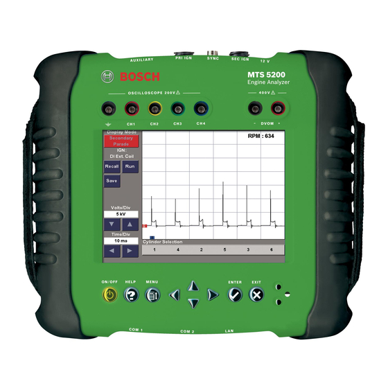
- Page 9 BOSCH MTS 5200 LAB SCOPE Presented by Bob Pattengale NAVIGATING THE MTS 5200 (CONTINUED) Primary & Secondary Ignition Once the firing order has been chosen, the ignition scope screen appears and is configured for primary ignition. Notice that all eight cylinders are displayed in the correct firing order across the bottom of the screen but the patterns for each cylinder are very small.
- Page 10 BOSCH MTS 5200 LAB SCOPE Presented by Bob Pattengale NAVIGATING THE MTS 5200 (CONTINUED) Primary & Secondary Ignition If you are in doubt about how the connections from the tool to the vehicle should be made, click on the menu option “Lead Help” in the left sidebar of the screen. As you can see in the above screen capture, a detailed schematic will appear on the screen giving you good direction on how to make the connections.
-
Page 11: Trigger Set Up
BOSCH MTS 5200 LAB SCOPE Presented by Bob Pattengale NAVIGATING THE MTS 5200 (CONTINUED) Primary & Secondary Ignition Trigger Set-Up While viewing live data, you can access all trigger properties through the Trigger Setup touch screen display button to the left of the signal display area as illustrated in the screen capture above. -
Page 12: Freeze
BOSCH MTS 5200 LAB SCOPE Presented by Bob Pattengale NAVIGATING THE MTS 5200 (CONTINUED) Primary & Secondary Ignition Freeze Also in the main menu is a menu option called “Freeze”. The Freeze button is available any time the MTS 5200 is collecting data in any of the display modes. The Freeze button stops the collection of live data and freezes the signal on the display, allowing you to analyze the frozen signal. -
Page 13: Superimposed Display
BOSCH MTS 5200 LAB SCOPE Presented by Bob Pattengale NAVIGATING THE MTS 5200 (CONTINUED) Primary & Secondary Ignition Superimposed Display Superimposed Display mode allows you to view the waveform of each cylinder in the firing order on a single screen, simultaneously. Each cylinder waveform is positioned beginning with the firing spike at the trigger position. -
Page 14: Raster Display
BOSCH MTS 5200 LAB SCOPE Presented by Bob Pattengale NAVIGATING THE MTS 5200 (CONTINUED) Primary & Secondary Ignition Raster Display Raster Display mode allows you to view the waveform of each cylinder in the firing order on a single screen, simultaneously. Selecting a cylinder from the Cylinder Selection buttons at the bottom of the touch screen display causes the MTS 5200 to hide or display the selected cylinder. -
Page 15: Single Cylinder Display
BOSCH MTS 5200 LAB SCOPE Presented by Bob Pattengale NAVIGATING THE MTS 5200 (CONTINUED) Primary & Secondary Ignition Single Cylinder Display Single Cylinder Display mode allows you to view the waveform characteristics of a single cylinder in the firing order. By pressing the Cylinder Selection buttons at the bottom of the touch screen display, you have the ability to view each cylinder’s waveform individually. -
Page 16: Firing Volts Bar Chart Display
BOSCH MTS 5200 LAB SCOPE Presented by Bob Pattengale NAVIGATING THE MTS 5200 (CONTINUED) Primary & Secondary Ignition Firing Volts Bar Chart Display Bar Chart Display mode allows you to view the voltage levels of each cylinder in the firing order on a single screen. -
Page 17: Secondary Quick Check
BOSCH MTS 5200 LAB SCOPE Presented by Bob Pattengale NAVIGATING THE MTS 5200 (CONTINUED) Secondary Quick Check During diagnosis of a secondary ignition system you might encounter situations where you want to display information on one specific cylinder. A Diagnostic Trouble Code (DTC) such as a P0302 (cylinder #2 misfire) would direct you immediately to the cylinder. - Page 18 Although the Secondary Quick Check is fully functional on Distributor Ignition (DI) systems, some applications filter the ignition signal as it passes through the distributor. This distorts the signal at the individual spark plug wires. For this reason, Bosch recommends using the Secondary Ignition Mode on Distributor Ignition (DI) vehicles.
-
Page 19: Graphing Multimeter
BOSCH MTS 5200 LAB SCOPE Presented by Bob Pattengale NAVIGATING THE MTS 5200 (CONTINUED) Graphing Multimeter Graphing Multimeter is a powerful diagnostic tool that allows you to view circuit operation over extended periods of time. All measurements are plotted horizontally from left to right to show the measurement over time and vertically to display the measured value. -
Page 20: Dc Voltage Button
BOSCH MTS 5200 LAB SCOPE Presented by Bob Pattengale NAVIGATING THE MTS 5200 (CONTINUED) Graphing Multimeter DC Voltage Button DC voltage mode measures and displays the DC voltage of a sampled signal. The MTS 5200 can measure DC voltages from 0 - 200 volts. -
Page 21: Duty Cycle Button
Setup, and Units of Measure. Pressure Button This mode displays the pressure measured by the Bosch Pressure Transducer. The Pressure Transducer has a measurement range of 0-300 psi. Three different units of measure selections can be used: psi, kPa, or bar. Units of measure are selected in the Units of Measure utility located in the Analyzer Utilities/Setup menu. -
Page 22: Vacuum Button
Graphing Multimeter Vacuum Button This mode displays the pressure measured by the Bosch Vacuum Probe. The Vacuum Probe has a measurement range of 30 inHg – 15 psi (0-30 psia). Two different units of measure selections can be used: inHg and mbar. Units of measure are selected in the Units of measure utility located in the Analyzer Utilities/Setup menu. -
Page 23: Capturing A Snap Shot
BOSCH MTS 5200 LAB SCOPE Presented by Bob Pattengale NAVIGATING THE MTS 5200 (CONTINUED) Graphing Multimeter Capturing a Snap Shot The Snapshot function gives you the ability to capture, save, and playback a length of data collected from a vehicle. When a snapshot is captured, the MTS 5200 collects data from the vehicle for a length of time you select. - Page 24 BOSCH MTS 5200 LAB SCOPE Presented by Bob Pattengale NAVIGATING THE MTS 5200 (CONTINUED) Graphing Multimeter Capturing a Snap Shot Adjusting Trigger Point Pre- and post-trigger times are adjusted with the “Right” and “Left” arrow buttons on either the touch screen or the keypad. The pre-trigger setting is displayed on the left side of the Trigger Point adjustment bar and is displayed in seconds.
- Page 25 BOSCH MTS 5200 LAB SCOPE Presented by Bob Pattengale NAVIGATING THE MTS 5200 (CONTINUED) Graphing Multimeter Capturing a Snap Shot SNAPSHOT CONTROLS Main Menu The Main Menu button returns you to the main menu of the operating mode from which you accessed Snapshot mode.
-
Page 26: Playback Mode
BOSCH MTS 5200 LAB SCOPE Presented by Bob Pattengale NAVIGATING THE MTS 5200 (CONTINUED) Graphing Multimeter Capturing a Snap Shot RECORDING INDICATOR In the top left corner of the grid there is a text box that displays the status of the snapshot. - Page 27 BOSCH MTS 5200 LAB SCOPE Presented by Bob Pattengale NAVIGATING THE MTS 5200 (CONTINUED) Graphing Multimeter Playback Mode Snapshot The Snapshot button exits the Playback Mode and returns to the Snapshot menu where another snapshot can be captured. The Exit keypad button operates the Snapshot button as well. If an unsaved snapshot exists when the Playback Mode is exited, you are prompted to either save the snapshot to memory or disregard the snapshot.
- Page 28 BOSCH MTS 5200 LAB SCOPE Presented by Bob Pattengale NAVIGATING THE MTS 5200 (CONTINUED) Graphing Multimeter Playback Mode Once the Save button is pressed, the Save Options menu is displayed (see Figure 11-4). This menu offers the following selections: Save Snapshot This selection saves the complete snapshot to memory where it can be recalled and viewed from the File Manager.
-
Page 29: Digital Volt Ohm Meter (Dvom)
BOSCH MTS 5200 LAB SCOPE Presented by Bob Pattengale NAVIGATING THE MTS 5200 (CONTINUED) Digital Volt Ohm Meter (DVOM) Overview The Digital Volt Ohm Meter (DVOM) is a powerful diagnostic tool that allows you to determine specific values of different measurement modes. The DVOM modes include DC and AC voltages, resistance, continuity, and diode check. -
Page 30: Operating Modes
BOSCH MTS 5200 LAB SCOPE Presented by Bob Pattengale NAVIGATING THE MTS 5200 (CONTINUED) Digital Volt Ohm Meter (DVOM) Operating Modes There are five operating modes in the DVOM application. DC VOLTAGE DC voltage mode displays the DC voltage of a sampled signal in the DVOM. The MTS 5200 can measure DC voltage from 0 mV to ±400 V. -
Page 31: 4-Channel Oscilloscope
BOSCH MTS 5200 LAB SCOPE Presented by Bob Pattengale NAVIGATING THE MTS 5200 (CONTINUED) 4-Channel Oscilloscope Overview The 4-Channel Oscilloscope is an easy-to-use and versatile tool that allows access to any automotive computer-controlled circuit. Once you are familiar with the oscilloscope layout and features, you can take full advantage of the most powerful tool in its class. -
Page 32: Connecting Leads
BOSCH MTS 5200 LAB SCOPE Presented by Bob Pattengale NAVIGATING THE MTS 5200 (CONTINUED) 4-Channel Oscilloscope Connecting Leads Before using the oscilloscope, connect your leads to the color-coded ports positioned above the touch screen display on the face of the MTS 5200. The oscilloscope leads are shielded to eliminate noise and interference from the vehicle. -
Page 33: Component Selection
BOSCH MTS 5200 LAB SCOPE Presented by Bob Pattengale NAVIGATING THE MTS 5200 (CONTINUED) 4-Channel Oscilloscope Component Selection When you choose Component Selection, the oscilloscope automatically configures itself for the vehicle component you designate. After touching the Component Selection button on the touch screen display, you see a menu of vehicle component categories from which to choose. -
Page 34: Trigger Setup
BOSCH MTS 5200 LAB SCOPE Presented by Bob Pattengale NAVIGATING THE MTS 5200 (CONTINUED) 4-Channel Oscilloscope Trigger Setup The MTS 5200 has a set of trigger controls that determine the exact instant the trace begins the sweep across the screen. If a trigger is set at a specific voltage level, and the signal being sampled achieves that trigger level voltage, then the MTS 5200 displays the signal. - Page 35 BOSCH MTS 5200 LAB SCOPE Presented by Bob Pattengale NAVIGATING THE MTS 5200 (CONTINUED) 4-Channel Oscilloscope Trigger Setup Trigger Type There are four different types of triggers to choose from when viewing a signal—Auto, Normal, Single Shot, and Free Run. Trigger type is available in the Trigger Setup menu. When the Trigger Type button is selected from the upper left corner of the Trigger Setup menu, a pop-up menu appears with the four trigger types to choose from.
- Page 36 BOSCH MTS 5200 LAB SCOPE Presented by Bob Pattengale NAVIGATING THE MTS 5200 (CONTINUED) 4-Channel Oscilloscope Trigger Setup the trigger position. If the signal does not meet the trigger level condition, the MTS 5200 does not display a signal. If you lose the trigger condition while viewing a signal, the signal display area freezes and remains frozen until the signal reaches the trigger level.
-
Page 37: Signal Finder
BOSCH MTS 5200 LAB SCOPE Presented by Bob Pattengale NAVIGATING THE MTS 5200 (CONTINUED) 4-Channel Oscilloscope Signal Finder If you have correctly configured the oscilloscope but see no waveform on the touch screen display, Signal Finder provides a quick and easy way to find the signal and display it. Signal Finder examines the input signal and automatically adjusts the settings for your selected channels in order to display the signal. -
Page 38: Other Functions
BOSCH MTS 5200 LAB SCOPE Presented by Bob Pattengale NAVIGATING THE MTS 5200 (CONTINUED) 4-Channel Oscilloscope Cursors When the cursors are activated, a Cursor Information Box appears at the bottom of the display showing the delta measurement between the cursors. Cursor information appears in the units of measure that are applicable to the channel that is selected for cursor measurement (i.e., the... -
Page 39: Cranking Kv Test
BOSCH MTS 5200 LAB SCOPE Presented by Bob Pattengale NAVIGATING THE MTS 5200 (CONTINUED) Cranking kV Test The Cranking kV Test allows you to perform a quick diagnosis of the secondary ignition system’s ability to produce spark at cranking engine speed. This test gives you a simple pass/fail result along with detailed information about the health of the secondary ignition system. - Page 40 BOSCH MTS 5200 LAB SCOPE Presented by Bob Pattengale NAVIGATING THE MTS 5200 (CONTINUED) Vehicle Selection You must use the manual setup if you wish to select a vehicle with a Coil Near Plug (CNP) or Coil On Plug (COP) ignition system. CNP and COP vehicles are not currently included in the vehicle database.
-
Page 41: Analyzer Utilities
BOSCH MTS 5200 LAB SCOPE Presented by Bob Pattengale NAVIGATING THE MTS 5200 (CONTINUED) Vehicle Selection 5. Select the correct firing order on the Select Firing Order pop-up menu. The Page Down and Page Up buttons move you one complete page at a time, allowing faster access to the firing order selections. - Page 42 BOSCH MTS 5200 LAB SCOPE Presented by Bob Pattengale NAVIGATING THE MTS 5200 (CONTINUED) Analyzer Utilities (Setup) SET DATE AND TIME The MTS 5200 utilizes a date and time function in memory as part of its software function. Date and time are used to put a time stamp on files that are recorded and saved. To set the time and date, simply touch the Set Date and Time button, bringing up the Set Date/ Set Time menu.
-
Page 43: Analyzer Utilities (Tools)
BOSCH MTS 5200 LAB SCOPE Presented by Bob Pattengale NAVIGATING THE MTS 5200 (CONTINUED) Analyzer Utilities (Tools) SOFTWARE VERSION NUMBER Software Version displays internal MTS 5200 software information. The internal software version number and release date are displayed on the SW Version button. Once pressed the following information is displayed in the S/W Version Information screen: •... - Page 44 BOSCH MTS 5200 LAB SCOPE Presented by Bob Pattengale NAVIGATING THE MTS 5200 (CONTINUED) Analyzer Utilities (Tools) CHARGE BATTERY To charge the battery pack, connect the tester to a 12 VDC power source such as the vehicle battery or the 12-volt AC/DC power supply. You must select Start Battery Charging from the Analyzer Utilities/Tools/Charge Battery screen to start battery charging.
- Page 45 BOSCH MTS 5200 LAB SCOPE Presented by Bob Pattengale NAVIGATING THE MTS 5200 (CONTINUED) Analyzer Utilities (Tools) ENABLE IGNITION DEMONSTRATION The Enable Ignition Demonstration function allows for selection of a stored ignition waveform program. This program operates in DI Secondary Ignition, Secondary Quick Check, and Primary Ignition.
-
Page 46: Conclusion On Navigating The Mts 5200
BOSCH MTS 5200 LAB SCOPE Presented by Bob Pattengale NAVIGATING THE MTS 5200 (CONTINUED) Conclusion On Navigating The MTS 5200 This concludes the broad overview on navigating the MTS 5200. As stated at the beginning of this section, a more detailed description of the navigation process can be found in the owners manual included with the MTS 5200 and is also available for download at: http://www.boschdiagnostics.com/support/documentation/Pages/DiagnosticsDocumentation.a... -
Page 47: The Graphing Multimeter
BOSCH MTS 5200 LAB SCOPE Presented by Bob Pattengale THE GRAPHING MULTIMETER Throttle Position Sensor (TPS) In this portion of the presentation we are going to go a little deeper into the Graphing Multimeter function of the MTS 5200. Pictured right you can see that we have connected the lab scope to a demonstration board. - Page 48 BOSCH MTS 5200 LAB SCOPE Presented by Bob Pattengale THE GRAPHING MULTIMETER Throttle Position Sensor (TPS) A normal TPS sensor will have a low voltage with the throttle released and voltage going higher as the throttle is depressed. Pictured above is a waveform captured from the screen of the lab scope.
- Page 49 BOSCH MTS 5200 LAB SCOPE Presented by Bob Pattengale THE GRAPHING MULTIMETER Throttle Position Sensor (TPS) Pictured above is the same waveform from the demonstration board but the glitch switch on the board has been turned ON. Note that the pattern now has three distinct drops in voltage indicated by the three lines going down in the pattern.
-
Page 50: Frequency
BOSCH MTS 5200 LAB SCOPE Presented by Bob Pattengale THE GRAPHING MULTIMETER Frequency We just looked at a voltage waveform for a TPS using the MTS 5200 connected to a demonstration board. Now let’s look at a frequency waveform. A frequency waveform would be useful in diagnosing such things as a MAF sensor on Ford vehicles or even a CKP signal during a no start condition. -
Page 51: Coolant Sensor
BOSCH MTS 5200 LAB SCOPE Presented by Bob Pattengale THE GRAPHING MULTIMETER Frequency For this type of signal it is important to keep an eye on the minimum and maximum values. This is because if you had a Ford vehicle that had a hesitation problem, you would look for the minimum signal to fall to 0.0Hz. -
Page 52: The Lab Scope (Square Wave With & Without Glitch)
BOSCH MTS 5200 LAB SCOPE Presented by Bob Pattengale THE LAB SCOPE (SQUARE WAVE WITH & WITHOUT GLITCH) Using the lab scope on the connected to the variable frequency signal terminal of the demonstration board you can see that we have a waveform on the screen. Also note that the voltage goes off of the screen. - Page 53 BOSCH MTS 5200 LAB SCOPE Presented by Bob Pattengale THE LAB SCOPE (SQUARE WAVE WITH & WITHOUT GLITCH) Using the signal finder function is one way to set the scope up quickly, however it may not give you the display that you actually want. If we use the Component Selection function and actually choose the sensor that we are testing, we can set the scope up to view the patterns exactly how we want to.
-
Page 54: Triggers
BOSCH MTS 5200 LAB SCOPE Presented by Bob Pattengale THE LAB SCOPE (SQUARE WAVE WITH & WITHOUT GLITCH) Triggers The MTS 5200 has a set of trigger controls that determine the exact instant the trace begins the sweep across the screen. If a trigger is set at a specific voltage level, and the signal being sampled achieves that trigger level voltage, then the MTS 5200 displays the signal. - Page 55 BOSCH MTS 5200 LAB SCOPE Presented by Bob Pattengale THE LAB SCOPE (SQUARE WAVE WITH & WITHOUT GLITCH) Triggers Trigger edge set to “Rising” position A good way of understanding trigger points is this. Imagine that you are driving down the road and you have a camera in your hands and you want to take a series of pictures.
- Page 56 BOSCH MTS 5200 LAB SCOPE Presented by Bob Pattengale THE LAB SCOPE (SQUARE WAVE WITH & WITHOUT GLITCH) Triggers Single Shot Trigger Single Shot trigger is used when you want to capture a certain characteristic of a known signal. If the signal under examination does not reach your trigger threshold setting, the MTS 5200 does not display any signal.
-
Page 57: The Lab Scope (Injector Signal)
BOSCH MTS 5200 LAB SCOPE Presented by Bob Pattengale THE LAB SCOPE (INJECTOR SIGNAL) We have moved our test lead on the the demonstration board to the injector signal terminal. In the Signal Finder mode we have also selected Fuel Injectors from the Component Selection menu. -
Page 58: The Lab Scope (Missing Trigger)
BOSCH MTS 5200 LAB SCOPE Presented by Bob Pattengale THE LAB SCOPE (MISSING TRIGGER) An important thing we need to cover before moving on to the hands on portion are missing triggers (missing events). Depending upon how you set up your scope you may not be catching what you think that you should be catching. -
Page 59: The Lab Scope (Recording & Screen Capture Saving)
BOSCH MTS 5200 LAB SCOPE Presented by Bob Pattengale THE LAB SCOPE (RECORDING & SCREEN CAPTURE SAVING) The file management system of the MTS 5200 allows you to view and manipulate saved images, snapshots, and text files by using the following functions: •... -
Page 60: 1995 Nissan Ignition Case Study
BOSCH MTS 5200 LAB SCOPE Presented by Bob Pattengale 1995 NISSAN IGNITION CASE STUDY Now that we have covered the navigation and functions of the MTS 5200 it is time to take a look at the power it has when used in your diagnostic strategy. Up until now we have only demonstrated how to use the lab scope using one channel. - Page 61 BOSCH MTS 5200 LAB SCOPE Presented by Bob Pattengale 1995 NISSAN IGNITION CASE STUDY Coil Power (green) Coil Control (red) Coil Ground (blue) Coil #2 (yellow) Now that we know that the PCM is not commanding the coil to fire we have to find out why. The instructor has connected all four of the channels of the scope to the ignition coil as shown in the screen capture above.
- Page 62 BOSCH MTS 5200 LAB SCOPE Presented by Bob Pattengale 1995 NISSAN IGNITION CASE STUDY The first sensor that was the easiest to get to was the CMP sensor. As you can see in the waveform above, that at no time did the CMP sensor signal drop out, but the ignition pattern at the bottom is still dropping out intermittently.
- Page 63 BOSCH MTS 5200 LAB SCOPE Presented by Bob Pattengale 1995 NISSAN IGNITION CASE STUDY Crank Signal (blue) Signal (red) Since we have determined that the problem is NOT with the CKP sensor or the CMP sensor, we need to look closer at the relationship between the camshaft and the crankshaft.
- Page 64 BOSCH MTS 5200 LAB SCOPE Presented by Bob Pattengale 1995 NISSAN IGNITION CASE STUDY Pictured above is a screen capture of a CMP/CKP signal waveform taken from the IATN website. This waveform is showing us what a known good waveform for each looks like along with the relationship between the two.
-
Page 65: Live Vehicle Testing (Secondary Ignition Cop Wand)
BOSCH MTS 5200 LAB SCOPE Presented by Bob Pattengale LIVE VEHICLE TESTING (SECONDARY IGNITION COP WAND) In this portion of the presentation we are going to take a look at some of the basic signals and circuits underneath the hood of a live vehicle. We will use the MTS 5200 and demonstrate how you connect it to the most common signals that you will be testing. - Page 66 BOSCH MTS 5200 LAB SCOPE Presented by Bob Pattengale LIVE VEHICLE TESTING (SECONDARY IGNITION COP WAND) You can see in the screen capture above that this vehicle has a multi-strike ignition system as indicated by the three firing patterns in the waveform. The first thing we need to look at is the primary (1st strike) ignition pattern of each ignition coil.
-
Page 67: Live Vehicle Testing (Secondary Ignition Cop Loop)
BOSCH MTS 5200 LAB SCOPE Presented by Bob Pattengale LIVE VEHICLE TESTING (SECONDARY IGNITION COP LOOP) Many times on vehicles that have COP ignition systems it is difficult to spot a misfire at idle. Normally misfires on COP ignition vehicles occur when the vehicle is running down the road. To detect misfires while driving the vehicle we want to use a COP loop. - Page 68 BOSCH MTS 5200 LAB SCOPE Presented by Bob Pattengale LIVE VEHICLE TESTING (SECONDARY IGNITION COP LOOP) You can see in the screen capture above that the scope has been set up with the trigger point on the leading edge of the waveform. Also note that the Time/Div has been increased giving more resolution to the pattern for easier viewing.
-
Page 69: Secondary Ignition Testing With The Lab Scope
BOSCH MTS 5200 LAB SCOPE Presented by Bob Pattengale SECONDARY IGNITION TESTING WITH THE LAB SCOPE So far we have covered two ways to diagnose secondary ignition problems. We have used the COP wand and the COP loop but there is also another method you can try, and that is using the 4 channel lab scope to diagnose the ignition patterns. -
Page 70: Secondary Ignition Testing Review
BOSCH MTS 5200 LAB SCOPE Presented by Bob Pattengale SECONDARY IGNITION TESTING REVIEW We have covered several different methods of testing the secondary ignition. As not to confuse you lets recap the things that really count. 1. If you are performing any type of ignition repair or diagnostics, start with the COP wand. This is the quickest way you can get an ignition pattern on the screen of your lab scope. -
Page 71: Live Vehicle Testing (Fuel Pump)
BOSCH MTS 5200 LAB SCOPE Presented by Bob Pattengale LIVE VEHICLE TESTING (FUEL INJECTORS) The screen capture above illustrates what a known good injector pattern looks like on our subject vehicle. As with the previous ignition patterns, you can switch between channel 1 and channel 2 to compare signals. - Page 72 BOSCH MTS 5200 LAB SCOPE Presented by Bob Pattengale LIVE VEHICLE TESTING (FUEL PUMP) You will get very good at using this current probe as you get better at using your lab scope. You need to get in the habit of testing every fuel pump on every high mileage vehicle that comes through your shop.
- Page 73 BOSCH MTS 5200 LAB SCOPE Presented by Bob Pattengale LIVE VEHICLE TESTING (FUEL PUMP) Using a suitable scan tool we can duty cycle the fuel pump without the vehicle running, and analyze the waveform on the lab scope. If your scan tool is not capable of this, you may have to find another way to command the fuel pump on.
-
Page 74: Live Vehicle Testing (Tps - Gmm)
BOSCH MTS 5200 LAB SCOPE Presented by Bob Pattengale LIVE VEHICLE TESTING (TPS - GMM) For this portion of the presentation we are going to take a closer look at the throttle position sensor (TPS). The TPS is a very common sensor and when it fails you will usually have a hesitation or problems that are very similar to hesitations. -
Page 75: Live Vehicle Testing (Recap)
BOSCH MTS 5200 LAB SCOPE Presented by Bob Pattengale LIVE VEHICLE TESTING (TPS - GMM) In the screen capture above you can see that as we exercise the throttle from WOT to closed, the signal trace on the screen follows the movement indicating that the TPS is working correctly. -
Page 76: Mts 5200 Faq's
BOSCH MTS 5200 LAB SCOPE Presented by Bob Pattengale MTS 5200 FAQ’S Where To Find The Manual Again we want to congratulate you for taking the initiative in buying this DVD and taking the time to watch it. Also, don’t forget to download the users manual and read it thoroughly. you can find the users manual at: http://www.boschdiagnostics.com/support/documentation/Pages/DiagnosticsDocumentation.a... -
Page 77: Where To Find Shop Foreman Pro
BOSCH MTS 5200 LAB SCOPE Presented by Bob Pattengale MTS 5200 FAQ’S Where To Find Shop Foreman Pro Shop Foreman Pro can be downloaded free of charge at: http://www.boschdiagnostics.com/software/diagnosticssoftware/pages/software.aspx?type=un derhood From there make sure that you choose “MTS 3100 Mastertech” from the drop down menu. -
Page 78: Loading The Software On The Mts 5200
If you do not have the discs, feel free to get in touch with the customer service department at BOSCH and they will be happy to make arrangements to get a disc to you. - Page 79 BOSCH MTS 5200 LAB SCOPE Presented by Bob Pattengale MTS 5200 FAQ’S SFP Software Access - Website The other end of the crossover cable needs to be connected to the LAN port connection on the PC that you will be using. Once both connections have been made, power both the MTS 5200 and the PC.
-
Page 80: In Conclusion
BOSCH MTS 5200 LAB SCOPE Presented by Bob Pattengale IN CONCLUSION Practicing the techniques and tricks that we have showed you during this demonstration will help you to learn the ins and outs of the daily use of the MTS 5200. We have given you some common areas and issues that you will be using on a frequent basis to aid in your diagnostics.
Need help?
Do you have a question about the MTS 5200 LAB SCOPE and is the answer not in the manual?
Questions and answers