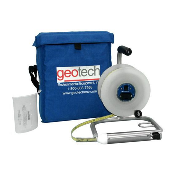
Summary of Contents for Geotech Keck Interface Probe
- Page 1 Keck Interface Probe Installation and Operation Manual Rev. 3 02/25/03 Part # 12050096...
-
Page 3: Table Of Contents
Table of Contents CHAPTER 1: SYSTEM DESCRIPTION..............5 ....................5 UNCTION AND HEORY ....................6 YSTEM OMPONENTS CHAPTER 2: SYSTEM INSTALLATION ..............7 CHAPTER 3: SYSTEM OPERATION ................. 8 KECK KIR DNAPL CORRECTION FACTORS............9 CHAPTER 4: SYSTEM MAINTENANCE ..............10 CHAPTER 5: SYSTEM TROUBLESHOOTING ............. - Page 4 DOCUMENTATION CONVENTIONS This uses the following conventions to present information: An exclamation point icon indicates a WARNING of a situation or condition that could lead to personal injury or death. You should not proceed until you read and thoroughly understand the WARNING WARNING message.
-
Page 5: Chapter 1: System Description
10 minutes of continuous operation before the unit shuts off. When the Keck Interface Probe is lowered down a well and contacts any fluid with a specific gravity of .60 or greater, the float will activate the visible and audible signals. -
Page 6: System Components
System Components Faceplate/ Electronics Assembly Reel Assembly Tape Guard Hanger Frame Assembly Tape Probe Assembly Assembly Figure 1 – System Components... -
Page 7: Chapter 2: System Installation
Chapter 2: System Installation The Keck Interface Probe Frame has a metal loop, the “hanger”, which may be used to hang the probe assembly on the well casing. If the Interface Probe frame will not hang on well head, use the tape guard to prevent damage to the tape. -
Page 8: Chapter 3: System Operation
Chapter 3: System Operation Step 1: Test the battery. Press the "ON/TEST" button. If the buzzer makes a loud signal and the light is visible, the battery is adequate for normal operation. Pressing the "ON/TEST" button provides 10 minutes of operation. Step 2: Test the instrument operation. -
Page 9: Keck Kir Dnapl Correction Factors
KECK KIR DNAPL CORRECTION FACTORS 2nd Reading ____’ + .08’ ____’ (total depth) MINUS — 1st Reading ____’ - .08’ ____’ (to product layer) CORRECTED PRODUCT THICKNESS ____’ Example: You find that a sinker (DNAPL) begins at 22.36 (1st reading) and the total depth of your well is 23.61 (2nd reading). Use the above formula to get your correct product thickness. -
Page 10: Chapter 4: System Maintenance
Chapter 4: System Maintenance Battery Replacement Replace the battery when the audible and visible signals become weak or the unit does not operate. Step 1: Gently remove the battery tray. Step 2: Remove the old battery and replace it with a new one. Be aware of the polarity (+, -) of the battery when placing the new battery in the tray. -
Page 11: Chapter 5: System Troubleshooting
Field calibration of the probe is not normally required. Chapter 5: System Troubleshooting Problem: No signal (audible or visible) from battery test. Solutions: 1) The battery is discharged. Check or change battery. • 2) The circuit is malfunctioning. Consult the manufacturer •... -
Page 12: Troubleshooting Continued
Replace tape and top cap. ** • 2) There is a loose connection in the circuit or the probe. Repair the connection. ** • 3) The float is damaged or missing. Replace the float. • **For Technical Assistance, Call Geotech 1-800-275-5325... -
Page 13: Chapter 6: System Specifications
Chapter 6: System Specifications Probe Material: Stainless Steel & Teflon® Weight: 19.75 oz. 560 g Diameter: 1.5 Inches 3.8 cm Length: 8.9 Inches 22.6 cm Conductivity Threshold (detects water at) : >6.7 S Minimum detectable hydrocarbon: .01 foot Tape Material: Tefzel coated stainless steel Length/Weight: 100 foot / 30 meters = 9 lbs... - Page 14 Operating temperature range: 32 – 140 °F 0 – 60 °C Storage temperature range: -40 – 158 °F -40 – 70 °C Response time: <10 milliseconds...
-
Page 15: Chapter 7: System Schematic
Chapter 7: System Schematic Figure 3 – Front and Side View... -
Page 16: Chapter 8: Replacement Parts List
Chapter 8: Replacement Parts List Figure 5 – Frame, Reel, & Control Assembly Parts List ITEM # PARTS DESCRIPTION PARTS LIST FRAME ASSEMBLY 52050027 REEL ASEMBLY, 100ft/30m 52050029 REEL ASEMBLY, 200ft/60m 52050030 REEL ASEMBLY, 300ft/100m 52050031 CONTROL ASSEMBLY 52050036 CLAMPING KNOB 12050524 RETAINING CLIP 12050001... - Page 18 Figure 6 – Tape/Probe Parts List Notes...
-
Page 19: The Warranty
For a period of one (1) year from date of first sale, product is warranted to be free from defects in materials and workmanship. Geotech agrees to repair or replace, at Geotech’s option, the portion proving defective, or at our option to refund the purchase price thereof. Geotech will have no warranty obligation if the product is subjected to abnormal operating conditions, accident, abuse, misuse, unauthorized modification, alteration, repair, or replacement of wear parts. - Page 20 NOTES...
- Page 21 NOTES...
- Page 22 NOTES...
- Page 24 Geotech Environmental Equipment, Inc 2650 East 40 Avenue Denver, Colorado 80205 (303) 320-4764 ● (800) 833-7958 ● FAX (303) 322-7242 email: sales@geotechenv.com website: www.geotechenv.com In Michigan Call Geotech Environmental Equipment Inc. 1099 East Grand River Road, Suite 6, Williamston, Michigan 48895...


Need help?
Do you have a question about the Keck Interface Probe and is the answer not in the manual?
Questions and answers