Axis 241Q User Manual
Axis 241q network-video server: users manual
Hide thumbs
Also See for 241Q:
- User manual (95 pages) ,
- Installation manual (55 pages) ,
- Specifications (2 pages)
Table of Contents
Advertisement
Advertisement
Table of Contents

Related Manuals for Axis 241Q


Summary of Contents for Axis 241Q
- Page 1 AXIS 241Q, AXIS 241S, AXIS 241QA and AXIS 241SA Video Servers User’s Manual...
- Page 2 • download user documentation and firmware updates • find answers to resolved problems in the FAQ database. Search by product, category, or phrases • report problems to Axis support staff by logging in to your private support area • visit the Axis Support Web at www.axis.com/techsup/ Safety Notice - Battery Replacement The Video Server uses a 3.0V CR2032 Lithium battery as the...
-
Page 3: Table Of Contents
Advanced - MPEG-4 Settings ......... . 24 Quad Stream Settings (AXIS 241QA/SA only) ......24 Audio (AXIS 241QA/SA only) . - Page 4 Y/C to BNC Cable (AXIS 241S/SA only) ........
-
Page 5: Product Description
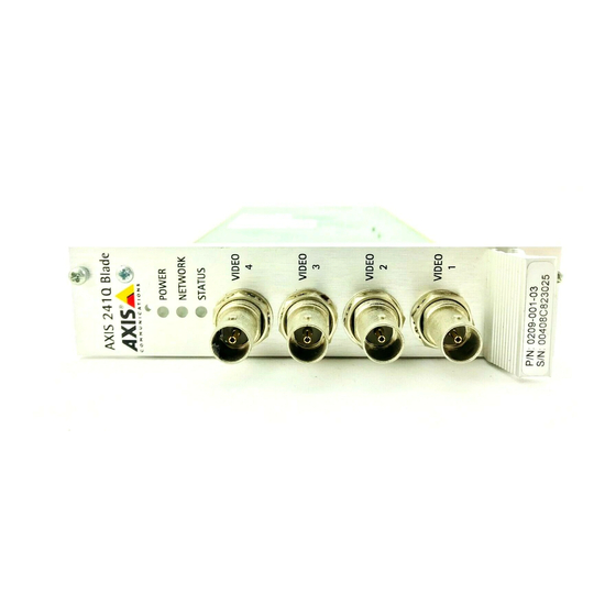
The Video Server is fully featured for security surveillance and remote monitoring needs. It is based on the AXIS ARTPEC-2 compression chip, and can digitize up to 4 analog video sources and make these available on the network as real-time, full frame rate Motion JPEG and/or MPEG-4 video streams. -
Page 6: Axis 241Q/Qa Front Panel
The built-in scripting tool allows basic applications to be created, providing basic surveillance solutions. For advanced functionality, the Video Server can be integrated via the use of the AXIS HTTP API (see www.axis.com/developer). AXIS 241Q/QA Front Panel... - Page 7 Physical connections made using e.g. 75 Ohm coax video cable have a recommended maximum length of 800 feet (250 meters). Line Out (AXIS 241QA only) - Mono audio output (line level), which can be connected to a public address (PA) system or an active speaker with a built-in amplifier. A pair of headphones can also be attached.
-
Page 8: Axis 241S/Sa Front Panel
Y/C video input Note: If the AXIS 241S/SA is to be connected in loop-through with other equipment, disable the input termina- tion by setting switch 1 to the up-position (OFF). Failure to do this may cause reduced image quality. Control Button - Press this button to restore the factory default settings, as described in Resetting to the Factory Default Settings, on page 53, or to install using AXIS Internet Dynamic DNS Service (see AXIS 241Q/S/QA/SA Video Server Installation Guide). - Page 9 Set DIP switch to OFF when in use. Line Out (AXIS 241SA only) - Mono audio output (line level), which can be connected to a public address (PA) system or an active speaker with a built-in amplifier. A pair of headphones can also be attached.
-
Page 10: Video Server Rear Panel
AXIS 241Q/S/QA/SA - Product Description Video Server Rear Panel Power Supply Connector - A single socket for connection of the PS-K power adapter. I/O Terminal connector - The I/O Terminal connector provides the physical interface to 4 digital transistor outputs, 4 digital inputs and an RS-485 interface. See Unit Connectors, on page 54 for more information. -
Page 11: Using The Video Server
2. Enter the IP address or host name of the Video Server in the Location/Address field of your browser. 3. Enter the user name and password set by the administrator. 4. A video image is displayed in your browser. AXIS 241Q/S/QA/SA - Using the Video Server... -
Page 12: The Live View Page
•To view streaming video in Microsoft Internet Explorer, you must set your browser to allow the AXIS Media Control (AMC) to be installed on your computer. AMC is required to use audio in the AXIS 241QA/SA. AMC also provides an MPEG-4 decoder for viewing MPEG-4 video streams. This decoder is installed the first time an MPEG-4 video stream is accessed. - Page 13 Right-click on the image to save it in on your computer. The AMC viewer toolbar (AXIS Media Control) is available in Microsoft Internet Explorer only and displays the following buttons: The Play/Stop buttons start and stop the media stream.
-
Page 14: Video And Audio Streams
The supported video object types are: • Simple - sets the coding type to H.263 • Advanced Simple - in Axis products, this sets the coding type to MPEG-4 Part 2 AMC (AXIS Media Control) supports both object types, whilst e.g. QuickTime™ requires the Simple object type. -
Page 15: Mpeg-4 Protocols And Communication Methods
The recommended method of accessing live video (MPEG-4 and/or Motion JPEG) and audio from the Video Server is to use the AXIS Media Control (AMC) in Microsoft Internet Explorer in Windows. This ActiveX component is automatically installed on first use, after which it can be configured by opening the AMC Control Panel applet from the Windows Control Panel. -
Page 16: Other Methods Of Accessing The Video Stream
AXIS 241Q/S/QA/SA - Video and Audio Streams RTP+RTSP This method (actually RTP over UDP and RTSP over TCP) should be your first consideration for live video, especially when it is important to always have an up-to-date video stream, even if some images do get dropped. This can be configured as multicast or unicast. -
Page 17: Other Mpeg-4 Clients
Using MPEG-4 When using MPEG-4, audio is streamed using the same protocol as the video stream. When audio is transmitted using MPEG-4, the Axis product sends synchronization information along with the streams to the client that is performing the synchronization. - Page 18 AXIS 241Q/S/QA/SA - Video and Audio Streams Java Applet The Java applet supports simplex audio.
-
Page 19: Configuring The Video Server
1. Start the browser and enter the IP address or host name of the Video Server in the location/address field. 2. The Live View page is now displayed. Click Setup to display the Setup tools. AXIS 241Q/S/QA/SA - Configuring the Video Server Setup... -
Page 20: Video & Image Settings
AXIS 241Q/S/QA/SA - Video & Image Settings Video & Image Settings The following descriptions show examples of the available features in the Video Server. For details of each setting, please refer to the online help available from each page. Click to access the online help. -
Page 21: Video Source Settings
Offset adjustments. See the online help for more information. AXIS 241S only: Select the physical connector the video source is connected to, BNC or Y/C. The AXIS 241S supports conversion between composite video and Y/C (s-video) using an ACC Y/C to BNC cable. -
Page 22: Overlay/Mask Settings
If you need to see an area of the video that is covered by an overlay or mask, a privacy mask cannot be bypassed. An overlay image, however, can be bypassed with the help of the AXIS HTTP API. Upload and use an overlay To upload an overlay image to the camera: 1. - Page 23 4. Click in the box beside Enable to enable one or more of the masks you have defined and click on Save. AXIS 241Q/S/QA/SA - Video & Image Settings Image Size The height and width of the overlay image in pixels must be exactly divisible by 4.
-
Page 24: Advanced - Mpeg-4 Settings
AXIS 241Q/S/QA/SA - Video & Image Settings Advanced - MPEG-4 Settings Tools for adjusting the MPEG-4 settings and for controlling the video bit rate. The MPEG-4 standard provides many different coding tools for various applications in different situations. As most MPEG-4 clients do not support all of these tools, it is usual to instead define and use subsets for different clients or groups of clients. -
Page 25: Audio (Axis 241Qa/Sa Only)
Select the video sources that the AXIS 241QA/SA will transmit and receive audio from. Audio Channels There are two mono audio channels between the AXIS 241QA/SA and other clients, one for receiving audio and one for transmitting audio. Each audio channel can be turned on or... - Page 26 Audio from an external microphone or a line source can be connected to the Line/Mic in jack of the AXIS 241QA/SA. The audio source can be set to Microphone or Line. If you are using a microphone, the input sensitivity can be set to High or Low. See Technical Specifications, on page 63 for the exact maximum levels.
- Page 27 AXIS 241Q/S/QA/SA - Audio (AXIS 241QA/SA only) If there are problems with the sound input being too low or high, it is possible to adjust the input gain for the microphone attached to the AXIS 241QA/SA. Audio Output If the sound from the speaker is too low or high it is possible to adjust the output gain for the active speaker attached to the Video Server.
- Page 28 AXIS 241Q/S/QA/SA - Audio (AXIS 241QA/SA only) When the incoming sound is louder than the threshold, it will pass without any changes. When lower than the threshold, the incoming sound will be reduced by a certain attenuation factor. The threshold value should be set higher than the background noise, but lower than the useful audio.
-
Page 29: Live View Config
These are the tools for deciding the layout of the Live View page. The layout can be set in 3 ways: • Use Axis look - the layout is unchanged. • Use custom settings - modify the default page with your own colors, images etc. - Page 30 AXIS 241Q/S/QA/SA - Live View Config Files Your own web files, background picture, color etc. must first be uploaded to the Video Server in order to be available for selection in the Custom Settings setup dialog. Once uploaded, the files are shown in the drop-down list.
-
Page 31: Html Examples
AXIS 241Q/S/QA/SA - Live View Config For more information on the Axis HTTP API, see the Support / Developer pages on the Axis Web site at http://www.axis.com. See also the section on PTZ, on page 38. Action Buttons These buttons can be used to manually trigger and stop an event from the Live View page. -
Page 32: External Video
AXIS 241Q/S/QA/SA - Live View Config External Video You can add links to other Axis network devices available over the network. These sources can be displayed on the Live View page, just as if they were video sources connected directly to the Video Server. -
Page 33: Event Configuration
When the setup is complete, the connection can be tested by clicking the Test button (the connection test takes approximately 10 seconds). AXIS 241Q/S/QA/SA - Event Configuration e.g. at a signal from an external device, such as a door switch or a motion sensor e.g. -
Page 34: Event Types
AXIS 241Q/S/QA/SA - Event Configuration Event Types An Event Type is a set of parameters describing how and when the Video Server is to perform certain actions. Example: If somebody walks past the connected camera, and an event has been configured to act on this, the Video Server can e.g. - Page 35 Buffer size - AXIS 241Q/QA - up to 36 MB buffer; AXIS 241S/SA - up to 9 MB buffer. The maximum length of time of the pre-/post-buffer depends on the selected image size and frame rate.
-
Page 36: Motion Detection
In the Motion Detection menu, you can configure the video source(s) for motion detection. The motion detection feature is used to generate an alarm whenever movement occurs (or stops) in the image. The AXIS 241Q/QA can use a maximum of 40 Include/Exclude windows, whilst the AXIS 241S/SA can use a maximum of 10. -
Page 37: Port Status
If the Normal state for a push button connected to an input is set to Open circuit, as long as the button is not pushed, the state is inactive. If the button is pushed, the state of the input changes to active. AXIS 241Q/S/QA/SA - Event Configuration for descriptions of each available option. -
Page 38: Pan Tilt Zoom
AXIS 241Q/S/QA/SA - Pan Tilt Zoom Pan Tilt Zoom Installing PTZ Devices The Video Server supports several PTZ devices. Please see www.axis.com for a complete list of supported devices, and to obtain the correct driver. Follow the instructions below to install a PTZ device: 1. -
Page 39: Axis 241Q/S/Qa/Sa
Note: Advanced users and application developers can also use the Axis Application Programming Interface and HTTP specification for generic control of PTZ devices using CGI commands or a TCP/IP client. Please refer to the Axis Website at www.axis.com for further information. -
Page 40: Ptz Controls
AXIS 241Q/S/QA/SA - Pan Tilt Zoom PTZ Controls If the Video Server has been appropriately configured, the Live View page will display the controls available for the installed Pan Tilt Zoom (PTZ) device. The administrator can enable/disable the controls for specified users. - Page 41 AXIS 241Q/S/QA/SA - Pan Tilt Zoom In contrast, when using an absolute driver, each position on the bar (see right) represents a defined position in the device’s range of movement, with the center of the bar representing the point midway between the two extremes of movement.
-
Page 42: Guard Tour
AXIS 241Q/S/QA/SA - Pan Tilt Zoom Preset Positions Also available with many PTZ devices are Preset positions. These presets are selected from the drop-down Source list on the Live View page and will move and/or zoom the camera to a pre-defined position, i.e. to cover an area of particular interest. Events can also be configured to go to preset positions when triggered. - Page 43 AXIS 241Q/S/QA/SA - Pan Tilt Zoom OSD Menu - If the PTZ unit supports an internal configuration menu, this can be accessed using the On-Screen Display (OSD). Configure the analog camera by opening and navigating through its internal menu in this display.
- Page 44 PTZ control command. 2. Event - You can set up the AXIS 241Q/S/QA/SA to take control of the queue and move to a specific position for 20 seconds when triggered by an alarm. The event will immediately be place first in queue except when an administrator is in control.
-
Page 45: System Options
Video Server into external Web pages, check the Referrals box and enter the IP address or Host name of the computer that hosts the Web pages with the included video stream. Multiple IP addresses/host names can be defined and are separated by semicolons(;) AXIS 241Q/S/QA/SA - System Options... -
Page 46: Date & Time
AXIS 241Q/S/QA/SA - System Options Notes: •If the referrals feature is enabled and you wish to also allow normal access to the Live View page, the product's own IP address or host name must be added to the list of allowed referrers. -
Page 47: Network - Basic Tcp/Ip Settings
DHCP, you can choose to be notified of the change. Click Settings... and enter the required information. AXIS Internet Dynamic DNS Service - If the Video Server has been registered with the Axis Internet Dynamic DNS service and the IP address for the product changes, the service is updated to reflect the change. -
Page 48: Network - Advanced Tcp/Ip Settings
AXIS 241Q/S/QA/SA - System Options Network - Advanced TCP/IP Settings DNS Configuration DNS (Domain Name Service) provides the translation of host names to IP addresses on your network. Obtain DNS server address via DHCP - automatically use the DNS server settings provided by the DHCP server. -
Page 49: Socks
If the mail server requires SMTP authentication, check the box for Use authentication to log in to this server and enter the user name and password used for logging in. Several different methods of authentication are available. See the online help for more information. AXIS 241Q/S/QA/SA - System Options... -
Page 50: Snmp
I/O Ports - the pinout, interface support and the control and monitoring functions provided by this connector are described in Unit Connectors, on page 54. RS232 - The COM port RS-232 on the AXIS 241Q/S/QA/SA supports several operational modes listed on this page. For more information, please see COM Ports RS-232 and RS-485, on page 56. -
Page 51: Maintenance
Restore button. The settings will be restored to the previous configuration. Note: Backup and Restore can only be used on the same unit running the same firmware. This feature is not intended for multi-configurations or for firmware upgrades. AXIS 241Q/S/QA/SA - System Options... -
Page 52: Support
The System Overview gives a quick look over the status of the camera. Logs & Reports - when contacting Axis support, please be sure to provide a valid Server Report with your query. Information - The Log report and the Parameter List also provide valuable information for troubleshooting and when contacting Axis’... -
Page 53: Resetting To The Factory Default Settings
5. When the Status Indicator changes to Green (may take up to 1 minute), the process is complete and the Video Server has been reset. 6. Re-install the Video Server, as described in the Installation Guide. AXIS 241Q/S/QA/SA - System Options Status Indicator Control Button... -
Page 54: Unit Connectors
• COM Ports RS-232 and RS-485, on page 56 • Y/C to BNC Cable (AXIS 241S/SA only), on page 57 The D-Sub Connector The Video Server provides one 9-pin D-sub connector, providing the physical interface for an RS-232 port, used for connecting accessory equipment; such as stand-alone PTZ devices for the remote control of connected video cameras. -
Page 55: The I/O Terminal Connector
2. Push the cable into the connector block and secure it by fastening the screw. 3. Once all devices are connected, connect the connector block to the Video Server’s terminal connector. AXIS 241Q/S/QA/SA - Unit Connectors Description 7-20 VDC/min 8W. Electrically connected in parallel with PS-k power connector, provides an auxiliary connector for mains power to the unit. -
Page 56: Schematic Diagram - I/O Terminal Connector
HTTP • Pan Tilt Zoom (PTZ) - for controlling a PTZ device. A PTZ device requires a driver for its function. Drivers can be obtained from www.axis.com. Please see page 38 for infor- mation on how to connect PTZ devices. -
Page 57: Y/C To Bnc Cable (Axis 241S/Sa Only)
The AXIS 241S/SA supports conversion from Y/C (S-video) to composite video using an Y/C to BNC cable. The cable is available as an accessory - see the Axis Web site at: http://www.axis.com. Follow these instructions to connect the Y/C to BNC cable: 1. -
Page 58: Troubleshooting
Note: Pre-configured and customized settings will be retained for use when the new firmware is running (pro- vided the features are available in the new firmware) although this is not guaranteed by Axis Communica- tions. 1. Save the firmware file to your computer. The latest version of the Video Server firmware is available free of charge from the Axis Web site at www.axis.com/techsup or from your local distributor. -
Page 59: Emergency Recovery Procedure
Axis support at www.axis.com/techsup/ Support If you contact Axis support, please help us help you resolve your problems expediently by providing a server report, log file and a brief description of the problem. Server Report - go to Setup > System Options > Support Overview. The server report contains important information about the server and its software, as well as a list of the current parameters. - Page 60 Verify that you are using an AXIS PS-K power supply. A rescue firmware is running in the product. First, set the IP address using AXIS IP utility or ARP and Ping, (See AXIS 241Q/S/QA/SA Video Server Installation Guide). Then, using a browser, access the unit and download the latest firmware to the product, see Upgrading the Firmware, on page 58.
- Page 61 Problem with AMC To enable the updating of images in Microsoft Internet Explorer, set your Web browser to allow (Internet Explorer only) ActiveX controls. Also, make sure that AXIS Media Control (AMC) component is installed on your workstation. Installation of additional ActiveX...
- Page 62 If the microphone has a built-in amplifier then the DC power must be enabled on the Audio Settings page. The volume of the microphone or speaker connected to the AXIS 241Q/S/QA/SA is either too high or too low. Change the volume for the speaker or microphone in the Live View page.
-
Page 63: Technical Specifications
• Event notification via TCP, email, HTTP and external outputs • Pre- and post-alarm buffer of 9 MB per channel (approx 4 min CIF video at 4 fps) Pan/Tilt/Zoom • Drivers for all supported PTZ units available from www.axis.com • PTZ control queuing capability AXIS 241Q/S/QA/SA - Technical Specifications... - Page 64 • Analog composite video, PAL/NTSC autosensing inputs • AXIS 241Q/QA: 4 BNC video inputs • AXIS 241S/SA: 1 BNC video input, 1 BNC output (loop through) or Y/C video input • Ethernet 10BaseT/100BaseTX, RJ-45 • Terminal block: 4 alarm inputs, 4 output transistors (max 24V, 0.1 A), 2-wire RS-485/422 (half-duplex), alternative voltage input •...
- Page 65 • HxWxD = 42 x 140 x 155mm (1 11/16 x 5 1/2 x 6 1/8”) • Weight: 540g (1.2 lb) excluding power adapter Complimentary Software • AXIS Media Control (AMC) - ActiveX component software required for Microsoft Internet Explorer, installed automatically on first use. • Optional: AXIS IP Utility - Windows installation MPEG-4 licensing License for one MPEG-4 encoder and one MPEG-4 decoder included.
-
Page 66: General Performance Considerations
AXIS 241Q/S/QA/SA - Technical Specifications General performance considerations When setting up your system, it is important to consider how various settings and situations will affect performance. Some factors affect the amount of bandwidth (the bit rate) required, others can affect the frame rate, and some will affect both. If the load on the CPU reaches its maximum, this will also affect the frame rate. -
Page 67: Frame Rates - Motion Jpeg
• GOV structure = IP* 4CIF 2CIF expanded 2CIF QCIF *Note that setting the GOV structure to use “I-frames only” will increase the frame rate. AXIS 241Q/S/QA/SA - Technical Specifications fps (PAL/NTSC) fps (PAL/NTSC) 1 channel 4 channels 25/30 8/10... -
Page 68: Bandwidth
AXIS 241Q/S/QA/SA - Technical Specifications Bandwidth As there are many factors affecting bandwidth, it is very difficult to predict the required amounts. The settings that affect bandwidth are: • the image resolution • the image compression • the frame rate •... -
Page 69: Glossary
IP address to a hardware MAC address. A request is broadcast on the local network to find out what the MAC address is for the IP address. ARTPEC - Axis Real Time Picture Encoder - used for image compression. BOOTP - A protocol that can automatically configure a network device (give it an IP address). - Page 70 AXIS 241Q/S/QA/SA - Glossary to which a packet should be forwarded on its way to its final destination. A router is often included as part of a network switch (see below). RTP- Real-Time Transfer Protocol. A transfer protocol designed for the delivery of live content, e.g. MPEG-4.
-
Page 71: Index
AMC 15 Anonymous viewers 45 Audio input 26 Audio mode 25 Audio output 27 Audio transmission 17 AXIS Internet Dynamic DNS Service 47 AXIS Media Control 26 Backup 51 Bandwidth 14, 68 Basic TCP/IP settings 47 Buffers 35 CGI links 30, 41... - Page 72 AXIS 241Q/S/QA/SA - Index Maximum bandwidth 49 Motion detection 36 Motion JPEG 14, 17 MPEG-4 14, 17 MPEG-4 clients 17 MPEG-4 protocols 15 MPEG-4 settings 50 Multicasting 15 Network indicator 8 Network settings 47 Network traffic 49 Notification of IP address change 47...
- Page 73 AXIS 241Q/S/QA/SA - Index Video source 12, 21 Video streams 14, 16, 21 View size 12 Y/C to BNC cable 57...
Need help?
Do you have a question about the 241Q and is the answer not in the manual?
Questions and answers