
Related Manuals for Wacker Neuson ET12 02


Summary of Contents for Wacker Neuson ET12 02
- Page 1 Operator’s Manual Track excavator Machine model E12-02, 03, 04 Edition Document order number 1000280663 Language...
- Page 2 This document may be used by the receiver only for the designated purpose. It may in no way be duplicated or translated in any other language, in whole or in part, without prior permission in writing from the manufacturer. No reproduction or translation of this publication, in whole or part, without the written consent of Wacker Neuson Linz GmbH.
-
Page 3: Table Of Contents
Table of contents Table of contents Table of contents 1 Foreword 1.1 Operator’s Manual ..........................1-1 1.2 Warranty and liability ..........................1-7 2 Safety 2.1 Safety symbols and signal words ......................2-1 2.2 Qualification of operating personnel ..................... 2-2 2.3 Conduct ..............................2-3 2.4 Operation .............................. - Page 4 Table of contents Maintenance 7.1 Information on maintenance ......................... 7-1 7.2 Maintenance overview .......................... 7-2 7.3 Fluids and lubricants........................... 7-10 7.4 Maintenance accesses ........................7-14 7.5 Cleaning and maintenance ......................... 7-20 7.6 Lubrication work..........................7-23 7.7 Fuel system ............................7-26 7.8 Engine lubrication system........................
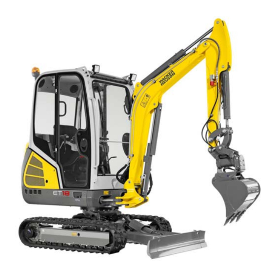
- Page 5 Declaration of conformity Declaration of conformity Declaration of conformity EC Declaration of Conformity Manufacturer Wacker Neuson Linz GmbH, Flughafenstr. 7, 4063 Hörsching, Austria Product Machine designation Hydraulic excavator Model/version E12-02 Trade name ET18 Serial number Output in kW 13,4 Measured sound power level dB(A) 92.5...
- Page 6 Declaration of conformity EC Declaration of Conformity Manufacturer Wacker Neuson Linz GmbH, Flughafenstr. 7, 4063 Hörsching, Austria Product Machine designation Hydraulic excavator Model/version E12-03 Trade name ET20 Serial number Output in kW 13,4 Measured sound power level dB(A) 92.5 Guaranteed sound power level dB(A)
- Page 7 Declaration of conformity EC Declaration of Conformity Manufacturer Wacker Neuson Linz GmbH, Flughafenstr. 7, 4063 Hörsching, Austria Product Machine designation Hydraulic excavator Model/version E12-04 Trade name ET24 Serial number Output in kW 13,4 Measured sound power level dB(A) 92.5 Guaranteed sound power level dB(A)
- Page 8 Declaration of conformity Notes: EG-4 BA ET18, 20, 24 en* 1.5 * et18_20_24konf.fm...
-
Page 9: Foreword
Table of contents Foreword Index Foreword Foreword Operator’s Manual Information on this Operator’s Manual This Operator’s Manual is stored in the compartment under the seat if the machine is equipped with a canopy. If the machine is equipped with a cabin, this Operator’s Manual is stored behind the seat. - Page 10 1 Foreword Explanation of symbols and abbreviations Explanation of symbols • Identifies a list - Identifies a subdivision of a list ➥ Description of a result 1. Identifies an activity Follow the order of the activity! 2. Continuation of an activity Follow the order of the activity! A Identifies an alphabetical list B Continuation of an alphabetical list...
- Page 11 Foreword Abbreviations Auxiliary-hydraulics circuit Width Nominal width Roll Over Protective Structure (without losing contact with ROPS the ground) FOPS Falling Objects Protective Structure TOPS Tip Over Protective Structure FGPS Front Guard Protective Structure Stabilizer blade Shovel arm Vertical Digging System Hydrau- lic quick- Hydraulic quickhitch, Easy Lock...
- Page 12 1 Foreword Glossary All exchangeable equipment (for example buckets) released by Wacker Neu- Attachment son and developed for work with the machine. Working lights The lights on the roof, chassis and boom are referred to as working lights. The excavator is towed out of an immediate danger zone (railroad crossing or Towing job site, for example).
- Page 13 Foreword Right/left/front/rear These terms are used from the view of an operator in the cabin if the front of the cabin faces toward the stabilizer blade A. • 1: left • 2: right • 3: front • 4: rear Fig. 1 (symbolic representation) BA ET18, 20, 24 en* 1.5 * et18_20_24v100.fm...
- Page 14 1 Foreword Conversion table The rounded imperial values are indicated in brackets, for example 1060 cm³ (64.7 in³). Volume unit 1 cm³ (0.061 in³) 1 m³ (35.31 ft³) 1 ml (0.034 US fl.oz.) (0.26 gal) 1 l/min (0.26 gal/min) Unit of length 1 mm (0.039 in) (3.28 ft)
-
Page 15: Warranty And Liability
• Wacker Neuson Linz GmbH shall not be liable for injury and/or damage to property caused by failure to observe the safety instructions and the Operator’s Manual, and by the negligence of the duty to... - Page 16 1 Foreword Notes: BA ET18, 20, 24 en* 1.5 * et18_20_24v100.fm...
-
Page 17: Safety
Safety Safety Safety Safety symbols and signal words Explanation The following symbol identifies safety instructions. It is used for alerting you to potential personal hazards. DANGER DANGER identifies a situation causing death or serious injury if it is not avoided. Consequences in case of nonobservance. -
Page 18: Qualification Of Operating Personnel
2 Safety Qualification of operating personnel Owner’s duties • Only allow specifically authorized, trained and experienced persons to operate, drive and perform maintenance on the machine. • Do not allow persons to be trained or instructed by anyone other than an authorized and experienced person. -
Page 19: Conduct
Safety Conduct Prerequisites for operation • The machine has been designed and built in accordance with state-of- the-art standards and the recognized safety regulations. Nevertheless its use can cause danger to the operator or other persons, or damage to the machine. •... -
Page 20: Operation
2 Safety Operation Preparatory measures • Operation is only allowed with correctly installed and intact protective structures. • Keep the machine clean. This reduces injury, accident and fire hazards. • Safely store objects you carry with you in the places provided for this (for example in the storage compartment, drinks holder). - Page 21 Safety Job site • The operator is responsible for other persons. • Before starting work, familiarize yourself with the job site. This applies to, for example: - Obstacles in the job site and machine travel area - Any barriers separating the job site from public roads - Soil weight-bearing capacity - Existing overhead and underground lines - Special operating conditions (for example dust, steam, smoke,...
- Page 22 2 Safety Mechanical integrity • The operator and owner are obligated to operate the machine only in a safe and working condition. • Operate the machine only if all protective and safety-oriented equipment (for example protective structures such as a cabin or rollbar, removable safety devices) is installed and functional.
- Page 23 Safety Machine travel on public roads/sites • The specific national driving license is required. • Observe the national regulations (for example the road traffic regula- tions) during machine travel on public roads/sites. • Ensure that the machine is in compliance with the national regulations. •...
-
Page 24: Lifting Gear Applications
2 Safety Lifting gear applications Requirements • Have loads fastened and the operator guided by a qualified person having specific knowledge of lifting gear applications and the usual hand signals. • The person giving instructions to the operator must stay in visual contact with the operator when fastening, guiding or removing the load (maintain visual contact). - Page 25 Safety Lifting gear applications • The machine must be certified for lifting gear applications. • Observe the national regulations for lifting gear applications. • Lifting gear applications are procedures involving raising, transporting and lowering loads with the help of lifting and fastening gear. •...
-
Page 26: Trailer Operation
2 Safety Trailer operation Trailer operation • The machine must be certified for trailer operation. • Observe the national regulations for trailer operation. • The specific national driving license is required. • Carrying passengers on/in trailers is PROHIBITED. • Observe the maximum permissible vertical and trailer load. •... -
Page 27: Towing, Loading And Transporting
Safety Removing and fitting attachments • Before uncoupling or coupling hydraulic connections: - Stop the engine - Release the pressure in the operating hydraulics • Picking up and lowering attachments to the ground requires special care: - Pick up and safely lock the attachment in accordance with the Operator’s Manual. - Page 28 2 Safety Crane-lifting • Seal off the danger zone. • The crane and the lifting gear must have suitable dimensions. • Observe the machine’s overall weight – see “Technical data”. • Wear protective clothing and equipment when fastening, guiding and removing the machine (for example a hard hat, safety glasses, safety shoes).
-
Page 29: Maintenance
Safety Transportation • For the safe transportation of the machine: - The transport vehicle must have a sufficient load capacity and platform – see “Technical data” - The maximum weight rating of the transport vehicle must not be exceeded. • Use only lifting and fastening gear certified by a test/certification body, observe the inspection intervals. - Page 30 2 Safety Personal safety measures • Avoid any operational mode that might be prejudicial to safety. • Wear protective clothing and equipment (for example a hard hat, protective gloves, safety boots). • Tie back long hair and remove all jewelry. •...
- Page 31 Safety Preparatory measures • Attach a warning label to the control elements (for example “Machine being serviced, do not start”). • Before performing assembly work on the machine, support the areas to be serviced and use suitable lifting and supporting equipment for the replacement of parts over 9 kg (20 lbs.).
- Page 32 2 Safety Modifications and spare parts • Do not modify the machine and the work equipment/attachment (for example safety equipment, lights, tires, straightening and welding work). • Modifications must be approved by the manufacturer and performed by an authorized service center. •...
-
Page 33: Measures For Avoiding Risks
Safety 2.10 Measures for avoiding risks Tires • Have repair work on the tires only performed by trained technical personnel. • Check the tires for correct pressure and visible damage (for example cracks, cuts). • Check the wheel nuts for tightness. •... - Page 34 2 Safety Battery • Batteries contain caustic substances (for example sulfuric acid). When handling the battery observe the specific safety instructions and regulations relevant to accident prevention. • A volatile oxyhydrogen mixture forms in batteries during normal operation and especially during charging. Always wear gloves and eye protection when working with batteries.
- Page 35 Safety Handling oil, grease and other substances • When handling oil, grease and other chemical substances (for example the battery acid, coolant), observe the safety data sheets. • Wear appropriate protective equipment (for example protective gloves, safety glasses). • Be careful when handling hot consumables – burn hazard. •...
- Page 36 2 Safety Working near non-electric supply lines • Before performing any work, the operator must check whether there are any non-electric supply lines in the job site. • If there are non-electric supply lines, the operator must take safety measures (for example switching off the supply line) in agreement with the operating company or owner of the supply lines.
-
Page 37: Introduction
Introduction Introduction Introduction Machine overview Position Designation Working light on boom Roof lights (option) Lifting eye Rotating beacon (option) Door arrester Engine cover Fuel tank filler inlet Side cover Exhaust pipe Tie-down point for tying down the machine Stabilizer blade Travel gear Handhold Auxiliary hydraulics... -
Page 38: Brief Description Of Machine
3 Introduction Overview of model designations and trade names Machine model/machine designation Trade name E12-02 ET18 E12-03 ET20 E12-04 ET24 Brief description of machine The machine model ET18/ET 20/ET24 is a self-propelled work machine. Observe the legal regulations of your country. This machine is a versatile and powerful helper for moving earth, gravel and debris on construction sites and elsewhere. - Page 39 Introduction Cooling system The coolant temperature is monitored with the indicator light on the machine’s instrument panel. Cabin/canopy The cabin/canopy have been specially designed for protection in case of an accident. • ROPS/TOPS tested canopy (open version). • ROPS/TOPS tested cabin (closed version/option). •...
-
Page 40: Information And Regulations On Use
3-5. - Every other use is regarded as not designated for the use of the machine. Wacker Neuson will not be liable for damage resulting from this; The user/operating company alone will bear the risk. Designated use also includes observing the instructions set forth in the Operator’s Manual and observing the maintenance and service... - Page 41 In order to avoid damage to the machine, only the attachments listed below have been certified for installation on the machine. ► Contact a Wacker Neuson service center if you wish to use other attachments. Using attachments of other manufacturers, or attachments that have been released for other machine types, can reduce the machine’s output and...
- Page 42 3 Introduction Description of attachment Weight Capacity Machine Remarks 37 kg 0.035 m ET 18 (82 lbs) (1.24 ft 39 kg 0.037 m ET 18 Easy Lock quickhitch (86 lbs) (1.31 ft 46 kg 0.051 m3 ET 20 (101 lbs) (1.80 ft Bucket 400 mm (16 in) Standard bucket...
- Page 43 Introduction Description of attachment Weight Capacity Machine Remarks ET 18 65.4 kg 0.082 m ET 20 (144 lbs) (2.90 ft ET 24 Ditch cleaning bucket 1000 mm (39 ET 18 72 kg 0.078 m ET 20 Easy Lock quickhitch (159 lbs) (2.75 ft ET 24 75 kg...
-
Page 44: Labels
3 Introduction Labels WARNING Danger of accident due to missing or damaged labels! A missing, incomplete or poor indication of danger can cause serious injury or death. ► Do not remove warning and information labels. ► Immediately replace damaged warning and information labels. Information Type, quantity, and position of the labels depend on options, country and machine. - Page 45 Equipment feature (optional) Fig. 3 17-digit serial number (from 2012) For easier machine identification, Wacker Neuson introduced a 17-digit serial number for compact equipment in 2012 (for example for excavators). This serial number includes additional data, for example the manufacturer code and the production site.
- Page 46 3 Introduction Type labels Machine type label The type label is located at the front left on the upper carriage. Fig. 5Position of type label Description of attachment HYDRAULIC EXCAVATOR Vehicle serial no. / serial no. Machine serial number Fahrzeug Modell/model/modèle: Machine designation Leistung/performance: Engine output...
- Page 47 Introduction Canopy type label The type label is located behind the seat. Fig. 7Canopy type label Cabin type label The type label is located under the window on the left. Fig. 8Cabin type label FOPS screen type label The type label is located at the upper left of the chassis. Fig.
- Page 48 3 Introduction Warning labels (Canopy) (Cabin) 3-12 BA ET18, 20, 24 en* 1.5 * et18_20_24e300.fm...
- Page 49 Introduction The following states signs and symbols that do not contain explanatory text and that are not explained in the following chapters. Meaning Danger of serious or fatal injury. Stay clear of suspended loads or of the danger zone of the machine during operation.
- Page 50 3 Introduction Meaning Danger of serious crushing of hands. 1. Use the handles to open and close the front window. 2. Lock the front window with both locks. Position On the front window. Fig. 18Front window Meaning Accumulator is under high pressure. Always read the Operator’s Manual before performing maintenance or repairs.
- Page 51 Introduction Meaning Read the Operator’s Manual before starting the machine. Fasten the seat belt during operation. When leaving the machine Danger of serious crushing of body and even death. Serious crushing hazard. Keep a safe distance from the boom. Danger of serious damage to the machine. During machine operation on slopes, pay attention to the maximum gradient angle and maximum lateral angle of inclination.
- Page 52 3 Introduction Meaning Read the Operator’s Manual before starting the machine. Injury hazard due to rotating parts. • Open the engine cover only at engine standstill. Fig. 24Engine cover Burn hazard due to hot engine parts. Position On the engine cover. Meaning Burn hazard due to hot parts on the boom (lines, plug-and-socket connections, threaded fittings, hydraulic cylinders, couplings, etc.).
- Page 53 Introduction Information labels 3-17 BA ET18, 20, 24 en* 1.5 * et18_20_24e300.fm...
- Page 54 3 Introduction Meaning Only use diesel fuel with a sulfur content below 15 mg/kg. Position Next to the fuel tank filler inlet. Fig. 28Diesel Meaning (option) The reservoir contains biodegradable hydraulic oil. This label is notched on the side depending on the biodegradable hydraulic oil used.
- Page 55 Introduction Meaning Indicates the interval at a which lubrication point must be lubricated. Lubrication points/grease zerks marked green mean: lubrication every 50 hours or once a week. Lubrication points/grease zerks marked blue mean: lubrication every 10 Fig. 34Lubrication point hours or daily. Position On the upper carriage on the right in travel direction.
- Page 56 3 Introduction Meaning (option) Check before starting the machine the operating pattern that has been chosen. Label shows the lever position in which the ISO or SAE controls are selected. Wiring diagram Controls ISO controls Fig. 38ISO/SAE changeover SAE controls Position At the left under the operator seat.
- Page 57 Introduction Meaning (ET18/ET20) This label describes the pedal and control lever functions (control pattern A/ISO controls). Check before starting the machine the operating pattern that has been chosen. – see “ISO/SAE changeover” on page 3-20 Position On the roof window on right in travel direction. Fig.
- Page 58 3 Introduction Meaning (ET24) This label describes the pedal and control lever functions (control pattern A/ISO controls). Check before starting the machine the operating pattern that has been chosen. – see “ISO/SAE changeover” on page 3-20 Position On the roof window on right in travel direction. Fig.
- Page 59 Introduction Meaning Indication of maintenance intervals. Position On the roof window on right in travel direction. Fig. 47Maintenance plan Meaning This label describes the functions of the hydraulic quickhitch. Position Canopy: inside on the roof. Cabin: at the upper edge of the rear window. Fig.
- Page 60 3 Introduction 3-24 BA ET18, 20, 24 en* 1.5 * et18_20_24e300.fm...
-
Page 61: Putting Into Operation
Putting into operation Putting into operation Putting into operation Cabin/control stand Safety instructions regarding entry and exit CAUTION Falling hazard when entering or exiting! Entering or exiting incorrectly can cause injury. ► Keep the mandatory climbing aids clean. ► Use the mandatory climbing aids A for entering and exiting. ►... - Page 62 4 Putting into operation Information Do not use the bar on the door when entering or exiting the cabin on the right. Fig. 51Cabin entry and exit on the right (option) Locking and unlocking the door Opening the door from the outside: Pull handle A outward.
- Page 63 Putting into operation Releasing the door arrester Pull button A to release the door out of the arrester. Fig. 55Releasing the door arrester Opening the door to a gap NOTICE The door can be damaged. ► Bear in mind the larger width of the machine if the door is opened to a gap.
- Page 64 4 Putting into operation Opening/closing the front window CAUTION Crushing hazard! Be careful when opening and closing the front window. Injury hazard due to crushing of parts of body. ► Stay clear (extremities, clothing) of the window channel. ► Open and close the front window with both handles. ►...
- Page 65 Putting into operation Closing the front window 1. Press levers A on the left and right, and pull the front window downward with handles B on the left and right. Fig. 59Closing the front window 2. Press the front window fully forward and release levers A. Fig.
- Page 66 4 Putting into operation Opening the lower front window Fig. 61Lower front window Press levers A on the left and right, and pull the front window upward with handles B on the left and right until it engages. Fig. 62Opening the lower front window Closing the lower front window Keep levers A pressed on the left and right, and pull the lower front window downward with handles B on the left and right until it engages.
- Page 67 Putting into operation Opening the whole front window Fig. 64Whole front window 1. Press levers C on the left and right, and pull the front window upward with handles D on the left and right until it engages. Fig. 65Opening the whole front window 2.
- Page 68 4 Putting into operation 2. Keep levers B pressed on the left and right, and pull the lower front window downward with handles C. 3. Release levers B and let the window engage. Fig. 68Closing the front window 4. Keep levers C pressed on the left and right, and pull the lower front window downward with handles D.
- Page 69 Putting into operation Opening/closing the side window Open Press lever D and let the window engage in the required recess. Close Press lever D and close with handle E. Fig. 72Front side window Open Press lever D and let the window engage in the required recess. Close Press lever D and close with handle E.
- Page 70 4 Putting into operation Emergency exit WARNING Injury hazard during emergency exit! Can cause serious injury or death. ► Stop the engine. ► Only use the windows for exiting the cabin if the access (cabin door) is obstructed or if it cannot be opened. ►...
- Page 71 Putting into operation Seat adjustment WARNING Accident hazard due to distraction when adjusting the seat! Can cause serious injury or death. ► Adjust the seat only when the machine is at a standstill. Weight adjustment 1. Sit down on the operator seat. 2.
- Page 72 ► Seat belt buckle must not be obstructed by foreign bodies (paper or similar); otherwise the buckle latch cannot lock into place. ► The seat belt must be replaced by a Wacker Neuson service center after an accident, and the bearing capacity of the fastening points and seat fixtures must be checked.
- Page 73 Putting into operation Fastening the seat belt 1. Insert buckle latch A into seat belt buckle B with an audible click. 2. Tighten seat belt C by pulling at its end. Fig. 78Fastening the seat belt Unfastening the seat belt 1.
- Page 74 ► Seat belt buckle must not be obstructed by foreign bodies (paper or similar); otherwise the buckle latch cannot lock into place. ► The seat belt must be replaced by a Wacker Neuson service center after an accident, and the bearing capacity of the fastening points and seat fixtures must be checked.
- Page 75 Putting into operation Adjusting the rearview mirrors (option) WARNING Injury hazard to persons in the danger zone! Persons in the danger zone are possibly not seen and can be injured during backward machine travel. ► Adjust the existing visual aids (for example the rearview mirrors) correctly.
- Page 76 4 Putting into operation Adjusting the mirrors Adjust the mirrors in order to: • Ensure sufficient visibility from the operator seat onto the job site. • Ensure maximum visibility to the rear. • Ensure visibility of the rear left edge of the machine in the left mirror. •...
- Page 77 ➥ The machine may be put into operation. 7. The selected elements move: ➥ Stop operation immediately. ➥ Contact a Wacker Neuson service center and have the malfunction rectified. If the machine is equipped with a canopy (standard), raiseable control lever bases are installed on either side.
- Page 78 4 Putting into operation Fire extinguisher A fire extinguisher is not available, neither as standard nor optional equipment. A fire extinguisher according to DIN-EN 3 must be installed by a Wacker Neuson service center. A bracket for the fire extinguisher must be fastened on the C pillar on the left for the cabin or canopy.
- Page 79 ► Replace the complete protective structure if it is damaged, deformed or cracked. ► Contact a Wacker Neuson service center in case of doubt. ► Retrofit and repair work may only be performed by a Wacker Neuson service center. Information Machine operation is only allowed with a correctly installed and intact cabin or correctly installed and intact canopy.
- Page 80 4 Putting into operation Protective FOPS structure/small screen – category I (option) DANGER Crushing hazard! Falling objects! Causes serious injury or death. ► Install a protective FOPS structure in areas with danger of falling objects. ► Machine operation is prohibited without a protective FOPS structure. Information The protective FOPS structure corresponds to category I according to ISO 3449:1992...
- Page 81 Putting into operation 5. Mounting point for cabin/canopy: B 6. Tighten screws D (M12/10.9) and lock nuts on the left and right to 110 Nm (87 ft.lbs). 7. Install the mirrors in both positions C. Fig. 89FOPS mounting point (above on machine) Assembly (black screen) 1.
- Page 82 4 Putting into operation Protective Front Guard structure with integrated FOPS/category I respectively (option) DANGER Danger of piercing/penetration by objects from the front! Causes serious injury or death. ► A protective Front Guard structure with integrated FOPS must be installed in areas with danger from the front (for example pipes, tree trunks, etc.) and of falling objects.
- Page 83 Putting into operation Fig. 93Lower mounting point 6. Mounting point for cabin/canopy: B (upper)/D (lower) 7. Tighten screws F (M12/10.9) and lock nuts on the left and right to 110 Nm (87 ft.lbs). 8. Install the mirrors in both positions E. Fig.
- Page 84 Can cause injury. ► Stop machine operation immediately. NOTICE Only a Wacker Neuson service center may install the shatter protection for the first time. NOTICE Do not use brushes, steel wool or other abrasive cleaners for cleaning the polycarbonate disk.
- Page 85 Work range height A: 120 cm (47 in), E: 50 cm (20 in). Fig. 96Job site with shatter protection Figures 96 and 97 refer to work with a Wacker Neuson hydraulic hammer. Information Working with another attachment can modify the height of the job site.
- Page 86 4 Putting into operation Document box Canopy The compartment under the seat is used for storing the Operator’s Manual. A document box on the headliner is available as an option. Fig. 100Canopy Cabin (option) The compartment behind the seat is used for storing the Operator’s Manual.
-
Page 87: Overview Of Control Elements
Putting into operation Power outlet A 12 V outlet is located at the front left of the machine chassis. Fig. 102Position of outlet Swiveling console limit stop (option) Limits the limit stop on the left of the swiveling console for attachments with a max. - Page 88 4 Putting into operation Cabin Fig. 104Overview of control elements Fig. 104Control element overview – proportional controls 4-28 BA ET18, 20, 24 en* 1.5 * et18_20_24i400.fm...
- Page 89 Putting into operation Designation See page 5-16 Accelerator pedals/drive levers 2 Boom swivel/auxiliary hydraulics pedal (AUX I) 5-32, 5-30 3 Foot-operated push button for hydraulic quickhitch (option) 5-38 4 Control lever base 4-17 5 Horn 5-10 6 Control levers 5-13 7 Travel speed changeover 8 Stabilizer blade/travel gear extension/retraction (option) 5-21,...
- Page 90 4 Putting into operation Display element and switches Maximum assignment shown Switch panel on the right (cabin) Switch panel on control lever base on the left Switch panel (canopy) Fig. 105Display element and switches 4-30 BA ET18, 20, 24 en* 1.5 * et18_20_24i400.fm...
- Page 91 39 Hydraulic quickhitch (option) 40 Wiper/wash system (cabin) 5-11 5-12 41 Ventilation/heating (cabin) 5-10 42 Rotating beacon (option) 43 Automatic engine speed setting (option) 44 Not assigned 45 For Wacker Neuson service center 4-31 BA ET18, 20, 24 en* 1.5 * et18_20_24i400.fm...
-
Page 92: Indicator Lights And Warning Lights (Overview)
4 Putting into operation Indicator lights and warning lights (overview) Display element The display element provides information on problems and malfunctions. After switching on the starter, the indicator lights are checked during the first 2 seconds. During this time the current reading of the maintenance meter is displayed. -
Page 93: High Speed (2Nd Speed)
4 seconds and the engine can be started. (A glow plug preheats the air in the combustion chamber of the engine when the key is in this position.) Contact a Wacker Neuson service center if the indicator light does not go out. Safe load indicator light The safe load indicator gives the operator optical and acoustic warnings when the values of the stability table are reached or exceeded. -
Page 94: Hour Meter/Maintenance Meter
4 Putting into operation Symbol Designation Fuel level indicator Indicates the remaining amount of fuel in the tank. Refuel immediately if the segments reach the red range. Coolant temperature Indicates the current coolant temperature of the engine. The indicator light illuminates if the segments reach the red range. •... -
Page 95: Preparatory Work
Putting into operation Preparatory work Important information before putting the machine into operation Before putting the machine into operation, perform a visual check to ensure that: - there are no leaks, - no parts are damaged or loose, - there are neither persons nor objects, - or other sources of danger around the machine. - Page 96 4 Putting into operation Check lists The checklists below are intended to assist you in checking and monitoring the machine before, during and after operation. These checklists cannot claim to be exhaustive. If the answer to one of the following questions is NO, first rectify the cause of the fault (or have it rectified) before starting or continuing work.
- Page 97 Putting into operation Operation checklist After starting the engine and during operation, check and observe the following points: Page ✔ No. Question Anyone in the danger zone of the machine? Indicator light for engine oil pressure and alternator 4-32 charge function gone out? Coolant temperature of engine in normal range? 4-34 Do the pedals and control levers work correctly?
- Page 98 4 Putting into operation Putting into operation for the first time and running-in period Before putting the machine into operation for the first time, check it visually for exterior damage due to transport, and check whether the equipment supplied with the machine is complete. •...
-
Page 99: Starting And Stopping The Engine
Putting into operation Starting and stopping the engine Preparations for starting the engine Set the throttle to the middle position if the engine is cold. The starter cannot be actuated if the engine is already running (start repeat interlock). Do not run the starter for more than 10 seconds. Wait about 1 minute so the battery can recover and the starter does not overheat before trying again. - Page 100 ➥ Interrupt the start procedure and repeat it after about 1 minute. ➥ If the engine still does not start after the second try: contact a Wacker Neuson service center for error analysis. 6. As soon as the engine runs: 7.
- Page 101 Putting into operation Jump-starting the engine WARNING Explosion hazard in case of incorrect handling of battery! Can cause serious injury or death. ► Never jump start the engine if the battery is frozen. Dispose of a frozen battery. ► In order to avoid electrical short-circuit or overvoltage, the battery jumper cable connected on the positive terminals of the batteries must never be brought into contact with electrically conductive vehicle parts.
- Page 102 4 Putting into operation Low-load operation NOTICE The running behavior of the engine can be negatively affected if it runs at idling speed or high speed and at less than 20% of the load. ► Run the engine in regular operation at loads of over 20 %. Possible consequences of low-load operation are: •...
- Page 103 Putting into operation Battery master switch Abb. 111 NOTICE Possible damage to the electronics due to improper actuation of the battery master switch! ► Do not operate the battery master switch with a running engine. ► Actuate the battery isolator switch no sooner than two minutes after shutting down the engine.
- Page 104 4 Putting into operation 4-44 BA ET18, 20, 24 en* 1.5 * et18_20_24i400.fm...
-
Page 105: Operation
Operation Operation Operation Steering system See “Drive levers and accelerator pedals” Accelerator actuation Manual throttle Speed can be set continuously with throttle 18. • Position A: maximum engine speed • Position B: idling speed Fig. 114Manual throttle Travel speeds The machine has two speed ranges that can be selected with the stabilizer-blade lever 26. -
Page 106: Brake
5 Operation As soon as a hydraulic function is performed with the control levers/drive levers, diesel engine speed is automatically increased again to the engine speed adjusted with the throttle. Position Function Automatic engine speed set- Press switch 43 down ting is enabled, the indicator light in switch 43 illuminates Automatic engine speed set-... -
Page 107: Travel Operation
Operation Travel operation Drive position • Position the machine as shown. • Position the boom at the center and raise it about 20 to 30 cm (8 – 12 in) off the ground. Information During machine travel, raise the stabilizer blade sufficiently high off the ground to avoid ground contact on rough terrain. - Page 108 5 Operation Operating temperature range The following operating conditions must be fulfilled in order to ensure optimal output and a long service life of the machine. Do not operate the machine at ambient temperatures above +45 °C (+104 °F) or below −15 °C (−5 °F). BA ET18, 20, 24 en* 1.5 * et18_20_24b500.fm...
- Page 109 Operation Machine travel on slopes WARNING Accident hazard due to tipping over or slipping of machine on slopes! Can cause serious injury or death. ► Travel on slopes only on firm and level ground. ► Drive on slopes only with the telescopic travel gear extended (normal operation).
- Page 110 5 Operation Preparations for performing machine travel on slopes Perform straight-ahead machine travel on slopes. When changing position, do not exceed a maximum gradient angle of 15° and a maximum lateral angle of inclination of 10°. < 10° Fig. 118Driving on slopes Information Performing machine travel diagonally on slopes is prohibited.
- Page 111 Operation Lateral angle of inclination Do not exceed a maximum lateral angle of inclination of 10°. < 10° Fig. 122Lateral angle of inclination On lateral inclinations over 10°, pile up material to create a level surface that can be used as a platform for the machine. >...
- Page 112 5 Operation Parking the machine WARNING Accident hazard if machine tips over or rolls away after parking it! Can cause serious injury or death. ► Lower the boom and the stabilizer blade to the ground. ► Secure the machine accordingly (for example with chocks). 1.
-
Page 113: Differential Lock
Operation Differential lock Not available Lights/signaling system Working lights The switch is located on the control lever base on the left. WARNING Accident hazard due to blinded motorists! Can cause serious injury or death. ► Switch on the working lights on the job site on public roads only if road users are not expected to be blinded. - Page 114 5 Operation Interior light Switched on: Press the switch to the left. Switched off: Press the switch to the center position or to the right. Fig. 128Interior light Horn Press button 5 on the control lever on the right to actuate the horn. Fig.
-
Page 115: Wiper/Wash System (Option)
► Do not allow anyone to stay in the danger zone. ► Do not rely on the travel signal under any circumstances. ► If the travel signal does not sound, stop machine operation immediately and contact a Wacker Neuson service center (observe the relevant national regulations). Wiper/wash system (option) Front wiper The switch is located on the switch panel on the right. -
Page 116: Heating, Ventilation And Air Conditioning System
5 Operation Heating, ventilation and air conditioning system Ventilation/heating (option) The switch is located on the switch panel on the right. Position Function 1st position Press switch 41 down one step Low fan speed 2nd position Press switch 41 down two steps High fan speed Press switch 41 all the way up Fan is switched off... -
Page 117: Work Hydraulics
Operation Operation Work hydraulics Overview of pedals and control levers (Operating Pattern A) Symbol Designation Symbol Designation Left track (forward) Right track (forward) Left track (reverse) Right track (reverse) Extend stick Swivel upper carriage to the right Retract stick Swivel upper carriage to the left Swivel boom to the right Swivel boom to the left Lower the boom... - Page 118 5 Operation 5-14 BA ET18, 20, 24 en* 1.5 * et18_20_24b510.fm...
- Page 119 Operation Overview of pedals and control levers (Operating Pattern B) Symbol Designation Symbol Designation Left track (forward) Right track (forward) Left track (reverse) Right track (reverse) Extend stick Swivel upper carriage to the right Retract stick Swivel upper carriage to the left Swivel boom to the right Swivel boom to the left Lower the boom...
- Page 120 5 Operation Drive levers/accelerator pedals CAUTION Accident hazard! The machine moves in the opposite direction if the upper carriage is rotated by 180° and the drive levers/accelerator pedals are actuated. Injury hazard due to incorrect machine operation. ► Slowly and carefully actuate the pedals and control levers. NOTICE In order to avoid excessive track abrasion: ►...
- Page 121 Operation Rotating the upper carriage WARNING Accident hazard! Upper carriage can rotate a little bit further. Can cause serious injury or death. ► The upper carriage can rotate a little bit further as long as the hydraulic fluid has not reached its operating temperature yet. ►...
- Page 122 5 Operation Hydraulic swivel unit brake: The upper carriage’s rotation is sufficiently braked by moving the control lever on the left back to initial position. Moving the control lever in the opposite direction (counteraction) brakes the upper carriage with maximum hydraulic output. Mechanical swivel unit brake: A multidisk brake integrated in the rotation drive has an additional mechanical brake effect.
- Page 123 If the attachment does not move from the piece of wood: ➥ Machine is operational. If the attachment moves away from the piece of wood: ➥ Stop operation immediately. ➥ Contact a Wacker Neuson service center and have the malfunction rectified. Fig. 143Identifying the deviation 5-19...
- Page 124 ► Secure the wing nut on the changeover lever of the directional valve. NOTICE Do not operate the machine with a malfunctioning wing nut. ► Contact a Wacker Neuson service center and replace the malfunctioning wing nut. The directional valve is located at the left under the seat.
- Page 125 Operation Stabilizer blade Position Function The stabilizer blade is actuated. The telescopic travel gear is actuated. 1. Raise the control lever base. 2. Make sure that the lever A is situated left under the driver`s seat in position 1 . Fig.
- Page 126 5 Operation Changing the width of the stabilizer blade (option) NOTICE Damage to machine when driving through door frames, etc. ► Pay attention to the width of the stabilizer blade and of the telescopic travel gear when performing machine travel through passages. ►...
- Page 127 Operation Telescopic travel gear (option) WARNING Crushing hazard due to tipping over of machine. Can cause serious injury or death. ► Only perform work with an extended telescopic travel gear. ► Performing machine travel with a retracted telescopic travel gear is only allowed for machine travel over very short distances through passages.
- Page 128 5 Operation Position Function The stabilizer blade is actuated. The telescopic travel gear is actuated. 1. Raise the control lever base. 2. Make sure that the lever A is situated left under the driver`s seat in position 1 . Fig. 151Stabilizer blade/telescopic travel gear 3.
- Page 129 Operation 8. Set the travel gear to the desired position. Telescopic travel gear Position Extend Push lever B forwards. Retract Pull lever B backward. Fig. 156Extension and retraction 9. Raise the control lever base. 10.Bring lever A in position 1 . Information Only perform work with an extended telescopic travel gear.
- Page 130 5 Operation Proportional controls (option) The proportional controls make it possible to adapt the speed with which the attachments move. Moving the control lever slowly causes the attachment to move slowly. This control mode offers proportional operation of the auxiliary hydraulics depending on the position of slide switch A on the control lever.
- Page 131 Operation Hammer operation Important information regarding hammer operation Use the canopy version only with a shatter protection during hammer operation. If the machine is equipped with a cabin (option), the front window must be closed. – see chapter “ Shatter protection (option)” on page 4-24 WARNING Danger of piercing/penetration by objects from the front! Work involving risk of piercing/penetrating by objects from the front can...
- Page 132 ► Stop machine operation immediately if a hydraulic hose moves back and forth in an unusual manner. The pressure accumulator could be malfunctioning. Contact a Wacker Neuson service center and have the malfunction rectified immediately. ► Do not use the impact force of the attachment to perform demolition work.
- Page 133 Operation Switch over to breaker operation: Set the ball valve on the revolving superstructure on the right to breaker Hammer Grab opera- operation. operation (sin- tion (dual-cir- gle-circuit cuit function) function) Fig. 161Ball-type cock Hammer operation Position Switched on Actuate the pedal A in the rear Switched off Release the pedal A Fig.
- Page 134 5 Operation Information The auxiliary hydraulics is enabled when the machine is started. ► Pressing button A changes over to boom swivel. Fig. 164Changeover of boom swivel Additional control circuit – AUX I (option) Set the ball valve on the revolving superstructure on the right to grab Hammer Grab opera- operation.
- Page 135 Operation Proportionally controlled additional control circuit – AUX I (option) 1. Changeover to the dual-circuit function. The ball-type cock is located Hammer Grab opera- on the right in travel direction on the upper carriage. operation (sin- tion (dual-cir- gle-circuit cuit function) function) Fig.
- Page 136 5 Operation Swiveling the boom Press and hold button A on the control lever base on the left. Fig. 170Changeover of boom swivel Swiveling the boom to the right: Press pedal 2 forward. Swiveling the boom to the left: Press pedal 2 backward. Fig.
- Page 137 Operation Lifting gear applications DANGER Crushing hazard due to tipping over of machine. Causes serious crushing or injury resulting in death. ► Observe chapter Safety/Safety instructions regarding lifting gear applications. ► Do not exceed the weight specified in the stability table. ►...
- Page 138 5 Operation In lifting gear applications, switch on switch 38 for the safe load indicator. As soon as indicator light 32 illuminates and the warning sounds: • Reduce the load until the indicator light goes out and the warning no longer sounds.
- Page 139 Operation Additional control circuits 3rd control circuit – AUX II (option) Turn the rotary switch on the control lever base on the left to the required position. Fig. 175Setting the oil flow Operating the additional control circuit Oil flow to line on the left: Push slide switch 23 on the left-hand control lever to the left.
- Page 140 5 Operation Powertilt – AUX II (option) WARNING Crushing hazard due to rotating movements of the Powertilt unit! Can cause serious injury or death. ► Do not allow anyone to stay in the danger zone. Information For more information, see Easy Lock/Powertilt with Easy Lock Operator’s Manual.
- Page 141 Operation Adjust the required oil flow with the rotary switch on the control lever base on the left. Fig. 177Setting the oil flow Actuating the Powertilt unit Fig. 178Actuating the Powertilt unit Rotating the Powertilt unit to the left: Rotation Rotation the left the right...
- Page 142 5 Operation Hydraulic Easy Lock quickhitch (option) • Attend specific training before putting into operation. Training must be given by authorized technical personnel and must be understood by the operator. • For safety reasons, the quickhitch must be operated with two control elements.
- Page 143 Operation WARNING Danger of crushing due to incorrect operation of the hydraulic quickhitch system! For system-specific reasons, the quickhitch can also be operated with other hydraulic functions. This can cause serious injury or death. ► Operate the hydraulic quickhitch only with the function Raise stabilizer blade.
- Page 144 5 Operation ➥ Check pin F must be fully extended. ➥ The attachment engages. Fig. 183Extended check pin 6. Release the dozer blade lever J and foot-operated touch button E . ➥ The quickhitch closes. Fig. 184Stabilizer blade operation ➥ Check pin F must be fully retracted. Fig.
- Page 145 Operation Setting down an attachment 1. Move the attachment inward completely and position it at 5–10 cm (2– 4 in) above the ground. 2. Unlock switch D and press it to position 1. ➥ The quickhitch is enabled and the buzzer sounds. Fig.
- Page 146 5 Operation 5. Release the dozer blade lever J and foot-operated touch button E . ➥ The quickhitch closes. Fig. 191Foot-operated push button and stabilizer- blade lever ➥ Check pin F must be fully retracted. Fig. 192 Retracted check pin 6.
- Page 147 Operation Grab operation on the left: 1. Fit lever A onto the ball-type cock. 2. Set the ball-type cock to position B. ➥ The 90° notch indicates that grab operation is set. 3. Remove the lever after the changeover. Fig. 195Grab operation on the left 5-43 BA ET18, 20, 24 en* 1.5 * et18_20_24b510.fm...
- Page 148 5 Operation Connecting and disconnecting hydraulic couplings 1. Stop and park the machine. See “Preparing lubrication”. 2. Position the boom straight ahead at the center of the machine. 3. Lower the stabilizer blade to the ground. 4. Turn the starting key to position 1. 5.
-
Page 149: Attachments
Operation 5.10 Attachments Picking up WARNING Danger of fluid escaping under high pressure! Can cause serious injury or death. ► Do not allow anyone to stay in the danger zone. ► Before connecting or removing hydraulic lines from the attachment, ensure that the operating hydraulics is not under pressure. - Page 150 5 Operation Setting down WARNING Crushing hazard due to uncontrolled movements of the attachment! Can cause serious injury or death. ► Ensure that no one is in the danger zone. ► Lower the attachment to level and firm ground ensuring stability. Re-equipping the attachments is described below for a bucket.
- Page 151 Operation Releasing the pressure in the operating hydraulics 1. Stop the machine on firm, level, and horizontal ground. 2. Lower the attachment completely to the ground. 3. Lower the stabilizer blade to the ground. 4. Stop the engine. 5. Turn the starting key to position 1. 6.
- Page 152 5 Operation Retrofitting a bucket Removing 1. Lower the bucket to level ground with the flat side facing downward. 2. Stop and park the machine. Stop the engine. See “Preparing lubrication”. 3. Remove linch pins A. 4. First remove the bolt B, then bolt C; carefully drive out seized bolts with a breaker and brass punch.
-
Page 153: Work Operation
Operation 5.11 Work operation Inadmissible work procedures Working with the swivel force • Do not use the swivel force of the upper carriage to tear down walls or to create level surfaces. • Never ram the attachment into the ground when swiveling the upper carriage. - Page 154 5 Operation Working with the falling force by lowering the machine • Never use the dead weight of the machine for work. • Use only the hydraulic force of the cylinders. Fig. 204Working with the falling force Fig. 205Working with the falling force Fully lowering the stabilizer blade •...
- Page 155 Operation General information regarding work operation Travel operation Performing machine travel over obstacles (rocks, tree stumps, etc.) can put a heavy load on the undercarriage, and cause damage. Avoid performing machine travel over obstacles if possible. If it cannot be avoided, lower the boom to ground level and travel over the obstacle at low speed at the middle of the running gear.
- Page 156 5 Operation Working with the standard bucket The following section describes work operations with the machine equipped with the standard bucket (backhoe bucket 400 mm/16 in). The standard bucket is mainly used for earth-moving applications, namely for digging, loosening, picking up and loading loose or solid material. The standard position the stabilizer blade is on the excavation side of the machine.
- Page 157 Operation Loading material • Loading material on trucks is easier and more efficient if: - The machine is positioned at the rear end of the truck. - The loading platform of the truck is loaded by starting at the rear end. - Work is performed with the smallest possible swivel angle.
- Page 158 ► The piston rod must not touch the stabilizer blade. Fig. 216Working on slopes Hints for digging When planning and performing digging work, Wacker Neuson recommends that you observe the following points: • Exits from pits must be outside the digging line and as level as possible.
-
Page 159: Emergency Lowering
Operation 5.12 Emergency lowering DANGER Crushing hazard during boom lowering! Causes serious crushing or injury resulting in death. ► Do not allow anyone to stay in the danger zone. Information Lower the boom immediately after stopping the engine. Observe the following during emergency lowering: 1. -
Page 160: Options
7. The acoustic signal does not sound, or the indicator light does not illuminate. ➥ The machine may not be used for lifting gear applications. ➥ Contact a Wacker Neuson service center and have the malfunction rectified. Perform a functional check of the control lever base. - Page 161 Operation Switching on the safe load indicator The safe load indicator switch is located on the control lever base on the left. 1.Press switch 38 on the instrument panel down. Fig. 217Safe load indicator ➥ Indicator light 32 in the display element is used for monitoring. ➥...
- Page 162 5. Stop the engine. 6. Remove the starting key and lock the cabin. 7. Secure the machine and the attachment. 8. Contact a Wacker Neuson service center and have the malfunction rectified. Environment Use a suitable container to collect fluids and lubricants as they flow out and dispose of them in an environmentally friendly manner.
- Page 163 Operation Immobiliser A = operator’s key (blue key) For starting the machine. Scope of delivery includes 2 keys. B = master key (red key) Information Store the master key in a safe place. It is only used for coding new keys. All coded keys are deleted if the key remains in position 1 for more than 20 seconds.
- Page 164 5 Operation Tilting the upper carriage (Vertical Digging System) (option) DANGER Crushing hazard due to tipping over of machine! Serious crushing hazard causing death or serious injury. ► On a slope, position the machine so that the upper carriage is tilted toward the slope.
- Page 165 Operation NOTICE Tipping hazard of machine. Damage to machine due to open doors and covers. ► Perform smooth and slow movements with the machine. ► All doors and covers must be closed when tilting the machine. ► Tilt the machine only on firm ground. ►...
- Page 166 5 Operation Shovel bucket operation With some restrictions, Wacker Neuson backhoe buckets can also be used for shovel bucket operation. NOTICE Do not tilt the bucket fully back in shovel bucket operation, otherwise the bucket base can touch and damage the stick.
-
Page 167: Putting Out Of Operation/Back Into Operation
Operation 5.14 Putting out of operation/back into operation The specified measures refer to putting the machine out of operation and back into operation after more than 30 days. Putting out of operation temporarily Store the machine indoors if possible. If the machine has to be stored outdoors, place it on a wooden base (if possible) and cover it with a watertight tarp to protect it against humidity. - Page 168 Information If the machine was put out of operation over a longer period of time without performing the steps specified above, contact a Wacker Neuson service center before putting the machine back into operation. 1. Remove anticorrosion agents from bare metal parts.
-
Page 169: Permanently Putting Out Of Operation
Dispose of different materials and consumables separately and in an environmentally friendly manner. Disposal may only be performed by a Wacker Neuson service center. Observe the corresponding national guidelines regarding disposal. Environment Avoid damage to the environment. Do not allow environmentally damaging wastes to get into the ground or stretches of water and dispose of them in an environmentally friendly manner. - Page 170 5 Operation Notes: 5-66 BA ET18, 20, 24 en* 1.5 * et18_20_24b510.fm...
-
Page 171: Transport
► Start machine travel and tow away slowly. ► Ensure that no one is between the vehicles during towing. ► Have a recovery service or a Wacker Neuson service center tow the machine away if necessary. ► See chapter “Safety, section 2.8”. - Page 172 6 Transport 1. Ensure that the machine can be towed safely. 2. Use towing eye hook A of the machine for towing. 3. Use towing eye A only for towing. 4. Secure shackle B with the shackle pin and a lock pin. 5.
-
Page 173: Loading The Machine
Transport Loading the machine Important information regarding loading WARNING Accident hazard due to incorrect loading! Incorrect loading can cause accidents and serious injury or death. ► Do not allow anyone to stay in the danger zone. ► Observe the loading weight. Add the weight of subsequently installed accessories to the weight of the vehicle. - Page 174 6 Transport Crane-lifting WARNING Accident hazard due to incorrect loading! Incorrect loading can cause accidents and serious injury or death. ► Do not allow anyone to stay in the danger zone. ► Observe the loading weight. Add the weight of subsequently installed accessories to the weight of the vehicle.
- Page 175 Transport Mandatory length L1 of slings: Length Dimension Minimum 1300 mm (51 in) BA ET18, 20, 24 en* 1.5 * et18_20_24t600.fm...
-
Page 176: Transporting The Machine
6 Transport Transporting the machine Important information regarding transport The swivel unit brake is enabled if: • the control lever base is raised. • The starter is turned to position 0 or the engine is stopped. This secures the upper carriage against rotation. Tying down 1. - Page 177 Transport Fig. 231Lashing points on either side outside on the travel gear BA ET18, 20, 24 en* 1.5 * et18_20_24t600.fm...
- Page 178 6 Transport BA ET18, 20, 24 en* 1.5 * et18_20_24t600.fm...
-
Page 179: Maintenance
Have the maintenance, delivery inspection and the entries in the service booklet performed by a Wacker Neuson service center, otherwise warranty claims will not be acknowledged. It is therefore in the interest of the machine owner to perform the mandatory maintenance. - Page 180 7 Maintenance Maintenance overview Maintenance plan Daily maintenance (user) Inspection work (Check the following fluids and lubricants, check the oil levels after a test run and add oil if nec- Page essary) 7-31, 7-33, Check the fluids and lubricants (engine oil, engine coolant, hydraulic oil) 7-41 Check the radiator and hydraulic oil cooler for dirt, clean them if necessary 7-34...
- Page 181 Maintenance Daily maintenance (user) Option Check the load hook, joint rod, lifting eyes 7-50 Check the hydraulic quickhitch (Easy Lock) for damage Check the Powertilt for damage Weekly maintenance (every 50 operating hours) (user) Page Lubricate the machine according to the lubrication schedule Clean the lights/light system, signaling system, acoustic warning system Check V-belt condition and tension 7-39,...
- Page 182 Check labels and Operator’s Manual for completeness and condition All steps for maintenance once a day and once a week Every 250 (500, 750, 1000, etc.) operating hours (Wacker Neuson service center) Engine oil change (Tier IV final – from 2012) Engine oil filter change (Tier IV final –...
- Page 183 Maintenance Every 1000 (2000, 3000, 4000, etc.) operating hours or once a year (Wacker Neuson service center) Hydraulic oil replacement Replacement of hydraulic oil reservoir breather filter Drive gearbox oil replacement Replacement of air filter elements Check the pilot control filter for dirt, clean it if necessary...
- Page 184 7 Maintenance Lubrication plan Powertilt with hydraulic quickhitch (option) Vertical Digging System (option) BA ET18, 20, 24 en* 1.5 * et18_20_24w700.fm...
- Page 185 Maintenance Position Lubrication point Interval Quantity Boom Daily Stick cylinder Daily Bucket cylinder Daily Boom cylinder Daily Joint rod Daily Bucket pin Daily Joint rod pin Daily Swiveling console Daily Stabilizer blade Every week Ball bearing race Every week Swiveling cylinder Daily Control lever base Every week...
- Page 186 7 Maintenance Maintenance label Some maintenance may only be performed by a Wacker Neuson service center (see maintenance plan). *Motor oil change interval tier IV final (from 2012): First service at 50 hours of operation; then at 250, 500, 750 Fig.
- Page 187 Maintenance Explanation of symbols on the maintenance label Symbol Assembly Explanation General Visual check General Visual check of machine General Lubrication points Clean the radiator fins, water separator and fresh-air fil- General ter of the heating fuel system Replace the fuel filter Radiator Check the coolant Radiator...
-
Page 188: Fluids And Lubricants
7 Maintenance Fluids and lubricants Fluids and lubricants Season/temper- Unit Fluid/lubricant Specification Capacities ature -15 °C (-5 °F) About 3.5 l Diesel engine Engine oil SAE 10W-40 +45 °C (+104 °F) (0.9 gal) Hydraulic oil HVLP 46 19.1 liters Hydraulic oil reservoir Panolin HLP Synth 46 Year-round (5 gal) - Page 189 Maintenance Engine oil types Engine oil grade Ambient temperature (°C) ° SAE 10W SAE 20W SAE 10W-40 API CF, CF-4, CI-4; ACEA E3, E4, E5; SAE 15W-40 JASO DH-1 SAE 20 SAE 30 SAE 40 °F Additional oil change and filter replacement (hydraulic system) NOTICE An additional oil change and filter replacement can be required depending on how the machine is used.
- Page 190 7 Maintenance Hydraulic oil types Hydraulics Ambient temperature (°C) oil grade ° ISO VG32 HVLP 46 ISO VG46 ISO VG68 °F According to DIN 51524 section 3, ISO-VG 46. 7-12 BA ET18, 20, 24 en* 1.5 * et18_20_24w700.fm...
- Page 191 • Use only the biodegradable oils that have been tested and approved by Wacker Neuson. Contact a Wacker Neuson dealer for the use of other products that have not been recommended. In addition, ask the oil supplier for a written declaration of guarantee. This guarantee is applicable to damage occurring on the hydraulic components that can be proved to be due to the hydraulic oil.
-
Page 192: Maintenance Accesses
7 Maintenance Maintenance accesses Engine cover WARNING Burn hazard due to hot engine parts! Can cause serious injury or death. ► Stop the engine and allow it to cool down at least 10 minutes. WARNING Injury hazard due to rotating parts! Rotating parts can cause serious injury or death. - Page 193 Maintenance Cover on the left Opening: 1. Stop and park the machine. Stop the engine. See “Preparing lubrication”. 2. Open the engine cover. 3. Pull out lock A. ➥ The side cover is folded sideways. Fig. 234Opening the lock 4. To unlock bow clip B, press and hold it downward. 5.
- Page 194 7 Maintenance 2. Press bow clip B downward and hitch it. 3. Position lock D opposite notch B. 4. Press side cover C toward the machine with both hands until it engages with an audible click. 5. Close the engine cover. Fig.
- Page 195 Maintenance Removing/installing the cabin/canopy DANGER Danger of accidents when performing machine travel without cabin/ canopy! Causes serious injury or death. ► Performing machine travel with a removed cabin/canopy is only allowed for performing machine travel over very short distances. ► Fastening the seat belt is prohibited. ►...
- Page 196 7 Maintenance 6. Install the lifting gear at the points on the cabin provided for lifting the machine. The required length L1 is 1000 mm (39.4 in). 7. Apply tension to the cabin with the lifting gear. Fig. 244Installing lifting gear 8.
- Page 197 Maintenance 12.Canopy: Remove screws E on either side. Fig. 248Screws (canopy) 13.Cabin (option): Remove screws E on either side. 14.Raise the cabin as follows: - Raise the control lever base. - Remove the starting key and carry it with you. - Close the doors, windows and all covers.
-
Page 198: Cleaning And Maintenance
7 Maintenance Cleaning and maintenance Important information on cleaning and maintenance Cleaning the machine is divided into 3 separate areas: • Inside the cabin. • Exterior of the machine. • Engine compartment. The wrong choice of cleaning equipment and agents can impair the operating safety of the machine on the one hand, and on the other undermine the health of the persons in charge of cleaning the machine. - Page 199 Maintenance Use of solvents NOTICE Do not clean rubber and electrical parts with solvents. ► Do not use solvents, benzine, or other aggressive chemicals. Cleaning the cabin/canopy NOTICE Never use high-pressure cleaners, steam jets or high-pressure water to clean inside the cabin. ►...
- Page 200 Fastening screws on the hydraulic system • Line, bucket teeth and pin fastenings on the attachment Retighten loose connections immediately, and have them immediately replaced by a Wacker Neuson service center if necessary. 7-22 BA ET18, 20, 24 en* 1.5 * et18_20_24w700.fm...
-
Page 201: Lubrication Work
Maintenance Lubrication work Preparing lubrication 1. Stop the machine on firm, level, and horizontal ground. 2. Position the boom straight ahead at the center of the machine. 3. Lower the boom and the stabilizer blade to the ground. 4. Stop the engine. 5. - Page 202 7 Maintenance Live ring (ball bearing race) DANGER Crushing hazard. Do not tilt or rotate the upper carriage during lubrication! Serious crushing hazard causing death or serious injury! ► Park the machine as shown in Fig. 250. ► Do not rotate the upper carriage. ►...
- Page 203 Maintenance Control lever base CAUTION Crushing hazard! In the area of the moving parts of the control lever base. Injury hazard due to crushing of parts of body! ► Stay clear (extremities, clothing) of the moving parts. 1. Stop and park the machine. Stop the engine. See “Preparing lubrication”.
-
Page 204: Fuel System
7 Maintenance Fuel system Important information regarding the fuel system Information Fill up the tank with the correct fuel type at the end of each working day to prevent the formation of condensation water in the fuel tank. Do not fill the tank completey so the fuel can expand. - Page 205 Maintenance Filler inlet A of the fuel tank is located in the engine compartment. 1. Stop and park the machine. Stop the engine. See “Preparing lubrication”. 2. Open the engine cover. 3. Remove the filler cap. 4. Refuel. 5. Close the filler cap. 6.
- Page 206 3. Remove the starting key and carry it with you. 4. Bleed the fuel system again as described above. 5. Check for leaks after starting the engine. 6. Have a Wacker Neuson service center perform a check if necessary. 7-28 BA ET18, 20, 24 en* 1.5 * et18_20_24w700.fm...
- Page 207 Maintenance Checking the water separator Water separator Empty the water separator if the red indicator ring A rises to position B. Fuel filter Empty the fuel filter if the fuel/water mixture rises to position C. Fig. 255Water separator and fuel filter Emptying the water separator WARNING Explosion and fire hazard when handling fuel!
- Page 208 7 Maintenance Information Use a suitable container to collect fluids and lubricants as they flow out and dispose of them in an environmentally friendly manner. Emptying the fuel filter WARNING Explosion and fire hazard when handling fuel! Can cause serious burns or death. ►...
-
Page 209: Engine Lubrication System
► The oil level must be between the MAX and MIN marks. ► Use only the specified engine oil (refill with the same engine oil). ► Have the oil changed only by a Wacker Neuson service center. NOTICE In order to avoid engine damage, add the engine oil slowly so it can go down without entering the intake system. - Page 210 7 Maintenance Adding engine oil 1. Stop and park the machine. Stop the engine. See “Preparing lubrication”. 2. Open the engine cover. 3. Clean the area around the oil filler cap with a lint-free cloth. 4. Open filler cap B. 5.
-
Page 211: Cooling System
Maintenance Cooling system Important information regarding the cooling system The oil/water radiator is located behind the cover on the right, on the right side of the engine. It cools the diesel engine, and the hydraulic oil of the drive and operating hydraulics. NOTICE In order to avoid damage to the engine and radiator. - Page 212 13.Close and lock the engine cover. NOTICE Do not add a different coolant to the one in the reservoir. ► Use only the coolant prescribed by Wacker Neuson – see chapter “7.3 Fluids and lubricants” on page 7-10.
- Page 213 Maintenance NOTICE Dirt on the radiator fins reduces the radiator’s heat dissipation capacity and can cause damage to the diesel engine and the hydraulic system! ► Check and if necessary clean the radiator once a day. ► In dusty or dirty work conditions, clean more frequently than indicated in the maintenance plans.
-
Page 214: Air Filter
Maintenance 7 Maintenance 7.10 Air filter Important information regarding the air filter • Store filters in their original packaging and in a dry place. • Check air filter attachments, air intake hoses and the air filter element for damage, and immediately repair or replace them if necessary. •... - Page 215 Maintenance Replacing the air filter NOTICE Air filter elements degrade prematurely when in service in acidic air for longer periods of time. ► This risk is present, for example, in acid production facilities, steel and aluminum mills, chemical plants and other nonferrous-metal plants. ►...
- Page 216 7 Maintenance Checking the air intake NOTICE In order to avoid engine damage when crossing fords: ► Keep the opening of the engine air intake A above the water. ► Check once a day for cleanliness before putting the machine into operation.
-
Page 217: V-Belt
About 8 mm (0.31 in) 7. If the V-belt is damaged (cracks, wear, ruptures, etc.): ➥ Have the V-belt replaced by a Wacker Neuson service center. ➥ Replace the V-belt if it touches the base of the V-belt groove or if the pulleys are damaged. -
Page 218: Hydraulic System
► If the hydraulic system is filled with biodegradable oil, then use only biodegradable oil of the same type for filling up – observe the sticker on the hydraulic oil reservoir. ► Contact a Wacker Neuson service center if the filter of the hydraulic system is dirty. 7-40... - Page 219 Maintenance Checking the hydraulic oil level 1. Park the vehicle on firm, level, and horizontal ground. 2. Position the boom straight ahead at the center of the machine (see figure). 3. Lower the boom and the stabilizer blade to the ground. 4.
- Page 220 NOTICE Leaks and damaged pressure lines must be immediately repaired or replaced by a Wacker Neuson service center. This not only increases the operating safety of the machine but also helps to protect the environment. ► Leaks and damaged pressure lines must be immediately repaired or replaced by an authorised service centre.
- Page 221 NOTICE Leaks and damaged pressure lines must be immediately repaired or replaced by a Wacker Neuson service center. This not only increases the operating safety of the machine but also helps to protect the environment. ► Leaks and damaged pressure lines must be immediately repaired or replaced by an authorised service centre.
-
Page 222: Electrical System
7.13 Electrical system Important information regarding the electrical system Maintenance and repair work on the electrical system may be performed only by trained technical personnel and/or a Wacker Neuson service center! • Malfunctioning components of the electrical system must always be replaced by a Wacker Neuson service center. - Page 223 – see chapter “ Relays” on page 9-5 – see chapter “ Fuses” on page 9-5 Battery condition May be performed only by a Wacker Neuson service center. Charging the battery May be performed only by a Wacker Neuson service center.
-
Page 224: Heating, Ventilation And Air Conditioning System
7 Maintenance 7.14 Heating, ventilation and air conditioning system Checking/replacing the fresh-air filter Have maintenance performed only by a Wacker Neuson service center. 7.15 Washer system Important information regarding the washer system Only use glass cleaner (with antifreeze if necessary) for refilling. -
Page 225: Tracks
Maintenance 7.17 Tracks Important information regarding the tracks Track wear can vary according to work and ground conditions. Checking track tension DANGER Crushing hazard during work under the machine! Causes serious crushing or injury resulting in death. ► Ensure that no one is in the danger zone. ►... - Page 226 ► Open the lubricating valve only very carefully and do not unscrew it more than a revolution. ► Keep your face away from the lubricating valve connection. ► Contact a Wacker Neuson service center if this does not reduce track tension. ► Release grease only as described below. (Observe the safety...
- Page 227 ➥ If it is not correct: 8. Adjust again. 9. Should the tracks still be slack after pumping more grease, replace the tracks or the seals in the cylinders. Contact a Wacker Neuson service center in this case. Reducing tension 1.
-
Page 228: Maintenance Of Attachments
Have load hooks (Powertilt, Powertilt for Easylock) with inadmissible wear (for example beyond the tolerance), damage, deformations, surface cracks and corrosion immediately replaced by a Wacker Neuson service center. The nominal size must not be worn more than 10 % (max. tolerance). -
Page 229: Exhaust Gas Treatment
Maintenance 7.20 Exhaust gas treatment Not available 7.21 Machine preservation Machines are partly preserved at the factory (for example in the engine compartment). Operation in an aggressive environment (for example salt deposits) is prohibited. 7-51 BA ET18, 20, 24 en* 1.5 * et18_20_24w710.fm... - Page 230 7 Maintenance Notes: 7-52 BA ET18, 20, 24 en* 1.5 * et18_20_24w710.fm...
-
Page 231: Malfunctions
Malfunctions Malfunctions Malfunctions NOTICE Contact a Wacker Neuson dealer or customer service in case of malfunctions or signs that are not listed in the following tables or that persist after maintenance has been performed correctly. Diesel engine Malfunction/sign Possible cause... -
Page 232: Attachments
8 Malfunctions Attachments Powertilt unit Malfunction/sign Possible cause Remedy Repeat the work operation with less load. If this problem Powertilt does not maintain its posi- Internal release valve activated persists, contact a Wacker tion Neuson dealer or a Wacker Neuson service center A little play due to necessary Lateral movement of the bucket spacing between teeth is nor-... -
Page 233: Technical Data
Technical data Technical data Technical data Models and trade names Machine model/machine designation Trade name E12-02 ET18 E12-03 ET20 E12-04 ET24 Engine Engine ET18 ET20 ET24 Product Yanmar diesel engine Type 3TNV76-SNSE12 Design Water-cooled 4 stroke diesel engine Number of cylinders Displacement 1116 cm (68.1 in... - Page 234 9 Technical data Engine ET18 ET20 ET24 Product Yanmar diesel engine Type 3TNV80F-SSNS1 Design Water-cooled 4 stroke diesel engine Number of cylinders Displacement 1266 cm3 (77.3 in Nominal bore and 80 x 84 mm (3.1 x 3.3 in) stroke Power 12.8 kW/2200 rpm (17.2 hp/2200 rpm) Max.
-
Page 235: Traveling Drive/Axles
Technical data Traveling drive/axles Travelling drive ET18 ET20 ET24 Design Axial-piston motor with planetary drive Brake See drive lever Tracks Rubber tracks ET18 ET20 ET24 230 mm 250 mm Track width (9 in) (10 in) Number of tread rollers Steering system See drive lever Operating hydraulics Work hydraulics... - Page 236 9 Technical data Work hydraulics ET 24 Double variable displacement + twin gear pump Pump 11 + 11 + 8.2 + 2.7 cm³ (0.67 + 0.67 + 0.50 + 0.16 in 26.1 (P1) + 26.1 (P2) + 19.4 (P3) + 6.4 (P4) l/min Flow rate at 2375 rpm (6.9 + 6.9 + 5.1 + 1.7 gal/min at...
-
Page 237: Electrical System
Technical data Electrical system Electrical components ET 18/ET 20/ET 24 Alternator 12 V 55 A Starter 12 V 1.1 kW (1.5 hp) Battery 12 V 44 Ah Fuses The fuses are located behind the cover on the left. Fuses Rated current (A) ET 18/ET 20/ET 24 F10 F11 F6 F9 F5 50 A... - Page 238 9 Technical data Bulbs ET 18 ET 20 ET 24 Working lights/roof lights Halogen lamp 12 V 55 W H3 Interior light Festoon lamp 10x38 12 V/5 W Rotating beacon Halogen lamp 12 V-55 W H1 Powertilt (option) ET 18 ET 20 ET 24 Model size...
-
Page 239: Tightening Torques
Technical data Tightening torques General tightening torques Property class 10.9 12.9 10.9 Screws according to DIN 912, DIN 931, DIN 933, etc. Screws according to DIN 7984 Screw dimen- sions Nm (ft.lbs.) Nm (ft.lbs.) Nm (ft.lbs.) Nm (ft.lbs.) Nm (ft.lbs.) 5.5 (4) 8 (6) 10 (7) -
Page 240: Coolant
9 Technical data 9.10 Coolant Compound table Outside tempera- Distilled water Coolant ture Up to °C (°F) % by volume % by volume -37 (-34.6) Use the 1:1 concentration for warm outside temperatures, too, to ensure protection against corrosion, cavitation, and deposits. Do not mix the coolant with other coolants. -
Page 241: Vibration
Technical data 9.12 Vibration Vibration Effective acceleration value for the upper extremi- < Trigger value ties of the body (hand-arm vibration) < 2.5 m/s Effective acceleration value for the body (whole- < 0.5 m/s body vibration) Vibration values indicated in m/s². Directive 2002/44/EC of European Parliament and Council on minimum health and safety requirements regarding exposure of workers to risks arising from physical agents (vibration). - Page 242 9 Technical data Directives on reduction of vibration values in earth moving machines: • Perform correct adjustments and maintenance on the machine. • Avoid jerky movements during machine operation. • Keep slopes in a perfect condition. Whole-body vibration can be reduced with the following guidelines: •...
- Page 243 European Parliament and Council on minimum health and safety requirements regarding exposure of workers to risks arising from physical agents (vibration). Your Wacker Neuson dealer provides information on other machine functions reducing vibration and on safe operation. 9-11 BA ET18, 20, 24 en* 1.5 * et18_20_24t900.fm...
-
Page 244: Weight
9 Technical data 9.13 Weight Machine weight Weight ET 18 ET 20 ET 24 1582 kg 2057 kg Canopy (3,488 lbs) (4,535 lbs) Canopy tele- 1707 kg 1862 kg scopic travel (3,763 lbs) (4,105 lbs) gear 1817 kg 1941 kg 2166 kg Canopy VDS (4,006 lbs) - Page 245 Technical data Excavator forces According to ISO 6015 ET 18 ET 20 ET 24 Max. tearout force 11.2 kN 12.5 kN 15 kN (short stick) (2518 lbf) (2810 lbf) (3372 lbf) Max. tearout force 9.8 kN 11.1 kN 13.3 kN (long stick) (2203 lbf) (2495 lbf)
-
Page 246: Payload/Stability
9 Technical data 9.14 Payload/stability Safety instructions – lift capacity table The values of the lift capacity table apply to normal operation (for example excavating). The values of the stability table apply to lifting gear applications. DANGER Crushing hazard due to tipping over of machine. Causes serious crushing or injury resulting in death. - Page 247 Technical data Legend Symbolic representat Designation Explanation Reach from live ring center Load hook height Authorized lift capacity with horizontal boom With the stabilizer blade in travel direction With or without the stabilizer blade, 90° to travel direction Lowered stabilizer blade Raised stabilizer blade Telescopic travel gear extended 9-15...
- Page 248 9 Technical data All table values are specified in kg (lbs) under the following conditions: • Upper carriage not tilted. • Machine placed on firm, level and horizontal ground. • No bucket or other attachment (hammer, etc.) installed. The machine’s lift capacity is restricted by the hydraulic output and the hydraulic system’s stabilizing features.
- Page 249 Technical data Lift capacity table ET 18 Cabin and standard travel gear (short stick) 3.0 m (9'-10") 2.5 m (98 in) 2.0 m (79 in) 1.5 m (59 in) 2.5 m (98 in) (842) (639) (549) (807) (701) (604) 2.0 m (79 in) (847) (527)
- Page 250 9 Technical data Cabin and telescopic travel gear (short stick) 3.0 m (9'-10") 2.5 m (98 in) 2.0 m (79 in) 1.5 m (59 in) 2,5 m (98 in) (842) (842) (690) (807) (807) (758) 2.0 m (79 in) (847) (776) (569) (818)
- Page 251 Technical data Cabin, telescopic travel gear and VDS (short stick) 3.0 m (9'-10") 2.5 m (98 in) 2.0 m (79 in) 1.5 m (59 in) 2,5 m (98 in) (840) (840) (622) (798) (798) (723) 2.0 m (79 in) (849) (831) (520) (844)
- Page 252 9 Technical data Canopy and standard travel gear (short stick) 3.0 m (9'-10") 2.5 m (98 in) 2.0 m (79 in) 1.5 m (59 in) 2.5 m (98 in) (842) (591) (500) (807) (648) (553) 2.0 m (79 in) (847) (485) (406) (818)
- Page 253 Technical data Canopy and telescopic travel gear (short stick) 3.0 m (9'-10") 2.5 m (98 in) 2.0 m (79 in) 1.5 m (59 in) 2,5 m (98 in) (842) (842) (637) (807) (807) (699) 2.0 m (79 in) (847) (719) (522) (818) (818)
- Page 254 9 Technical data Canopy, telescopic travel gear and VDS (short stick) 3.0 m (9'-10") 2.5 m (98 in) 2.0 m (79 in) 1.5 m (59 in) 2,5 m (98 in) (840) (840) (564) (798) (798) (657) 2.0 m (79 in) (849) (774) (467)
- Page 255 Technical data Lift capacity tables ET 20 Cabin and telescopic travel gear (short stick) 3.5 m (11'-6") 3.0 m (9'-10") 2.5 m (98 in) 2.0 m (79 in) 2,5 m (98 in) (842) (783) (710) (849) (769) (697) (783) (783) (783) 2.0 m (79 in)
- Page 256 9 Technical data Cabin, telescopic travel gear and VDS (short stick) 3.5 m (11'-6") 3.0 m (9'-10") 2.5 m (98 in) 2.0 m (79 in) 2,5 m (98 in) (838) (774) (604) (833) (789) (617) (785) (785) (785) 2.0 m (79 in) (844) (672)
- Page 257 Technical data Canopy and telescopic travel gear (short stick) 3.5 m (11'-6") 3.0 m (9'-10") 2.5 m (98 in) 2.0 m (79 in) 2.5 m (98 in) (842) (725) (657) (849) (712) (644) (783) (783) (783) 2.0 m (79 in) (844) (620) (560)
- Page 258 9 Technical data Canopy, telescopic travel gear and VDS (short stick) 3.5 m (11'-6") 3.0 m (9'-10") 2.5 m (98 in) 2.0 m (79 in) 2,5 m (98 in) (838) (719) (547) (833) (732) (558) (785) (785) (769) 2.0 m (79 in) (844) (622)
- Page 259 Technical data Lift capacity table ET 24 Cabin and standard travel gear (short stick) 3.5 m (11'-6") 3.0 m (9'-10") 2.5 m (98 in) 2.0 m (79 in) 2.5 m (98 in) (1,217) (970) (785) (1,206) (990) (802) (1,131) (1,131) (1,102) 2.0 m (79 in)
- Page 260 9 Technical data Cabin, standard travel gear and VDS (short stick) 3.5 m (11'-6") 3.0 m (9'-10") 2.5 m (98 in) 2.0 m (79 in) 2.5 m (98 in) (1,217) (948) (758) (1,206) (970) (776) (1,131) (1,131) (1,067) 2.0 m (79 in) (1,228) (825)
- Page 261 Technical data Canopy and standard travel gear (short stick) 3.5 m (11'-6") 3.0 m (9'-10") 2.5 m (98 in) 2.0 m (79 in) 2.5 m (98 in) (1,217) (908) (776) (1,206) (928) (734) (1,131) (1,131) (1,014) 2.0 m (79 in) (1,228) (789) (613)
- Page 262 9 Technical data Canopy, standard travel gear and VDS (short stick) 3.5 m (11'-6") 3.0 m (9'-10") 2.5 m (98 in) 2.0 m (79 in) 2.5 m (98 in) (1,217) (888) (690) (1,206) (908) (708) (1,131) (1,131) (979) 2.0 m (79 in) (1,228) (769)
- Page 263 Technical data Lift capacity tables VDS (upper carriage tilted) Boom downhill (15° slope) Boom uphill (15° slope) Symbolic representation Symbolic representation Designation Explanation Reach from live ring center Load hook height Authorized lift capacity with horizontal boom Without the stabilizer blade, 90° to travel direction Telescopic travel gear extended 9-31 BA ET18, 20, 24 en* 1.5 * et18_20_24t900.fm...
- Page 264 9 Technical data ET18 – VDS, cabin, boom uphill 3.0 m (9'-10") 2.5 m (98 in) 2.0 m (79 in) 1.5 m (59 in) Short stick Long stick Short stick Long stick Short stick Long stick Short stick Long stick Short stick Long stick 2,5 m...
- Page 265 Technical data ET18 – VDS, canopy, boom uphill 3.0 m (9'-10") 2.5 m (98 in) 2.0 m (79 in) 1.5 m (59 in) Short stick Long stick Short stick Long stick Short stick Long stick Short stick Long stick Short stick Long stick 2,5 m (98 in)
- Page 266 9 Technical data ET20 – VDS, cabin, boom uphill 3.5 m (11'-6") 3.0 m (9'-10") 2.5 m (98 in) 2.0 m (79 in) Short stick Long stick Short stick Long stick Short stick Long stick Short stick Long stick Short stick Long stick 2,5 m 293 (...
- Page 267 Technical data ET20 – VDS, canopy, boom uphill 3.5 m (11'-6") 3.0 m (9'-10") 2.5 m (98 in) 2.0 m (79 in) Short stick Long stick Short stick Long stick Short stick Long stick Short stick Long stick Short stick Long stick 2,5 m (98 in)
- Page 268 9 Technical data ET24 – VDS, cabin, boom uphill 3.5 m (11'-6") 3.0 m (9'-10") 2.5 m (98 in) 2.0 m (79 in) Long Short Short stick Long stick Short stick Long stick Short stick Long stick Short stick Long stick stick stick 2,5 m...
- Page 269 Technical data ET24 – VDS, canopy, boom uphill 3.5 m (11'-6") 3.0 m (9'-10") 2.5 m (98 in) 2.0 m (79 in) Long Short Short stick Long stick Short stick Long stick Short stick Long stick Short stick Long stick stick stick 2,5 m...
- Page 270 9 Technical data Safety instructions – stability table The values of the stability tables apply to lifting gear applications. DANGER Crushing hazard due to tipping over of machine. Causes serious crushing or injury resulting in death. ► Do not exceed the weight specified in the stability table. ►...
- Page 271 Technical data Legend Designation Explanation Reach from live ring center Load hook height in the respective range Authorized lift capacity with horizontal boom Stick short/long Authorized lift capacity applies to entire swiveling range of 360°. All table indications in kg (lbs) and horizontal position on firm and level ground without bucket or exchangeable attachment.
- Page 272 9 Technical data Stability tables ET 18 Cabin/canopy and standard travel gear Cabin/canopy and telescopic travel gear 9-40 BA ET18, 20, 24 en* 1.5 * et18_20_24t900.fm...
- Page 273 Technical data Cabin/canopy, telescopic travel gear and VDS Stability tables ET 20 Cabin/canopy and telescopic travel gear 9-41 BA ET18, 20, 24 en* 1.5 * et18_20_24t900.fm...
- Page 274 9 Technical data Cabin/canopy, telescopic travel gear and VDS Stability tables ET 24 Cabin/canopy and standard travel gear 9-42 BA ET18, 20, 24 en* 1.5 * et18_20_24t900.fm...
- Page 275 Technical data Cabin/canopy, standard travel gear and VDS 9-43 BA ET18, 20, 24 en* 1.5 * et18_20_24t900.fm...
- Page 276 9 Technical data Dimensions Overview ET18, ET20, ET24 9-44 BA ET18, 20, 24 en* 1.5 * et18_20_24t900.fm...
- Page 277 Technical data Standard / Telescopic travel ET18 telescopic travel gear + gear Height 2290 mm (7'-6'') 2390 mm (7'-10'') B1 Upper carriage width 990 mm (39 in) B2 Width with retracted travel gear 990 mm (39 in) B2 Width with extended travel gear (telescopic travel gear only) 1300mm (51 in) Transport length 3855 mm (12'-8'')
- Page 278 9 Technical data Telescopic travel Telescopic travel ET20 gear gear + VDS Height 2295 mm (7'-6'') 2385 mm (7'-10'') Upper carriage width 990 mm (39 in) Width with retracted travel gear 990 mm (39 in) Width with extended travel gear 1300mm (51 in) Transport length 4050 mm (13'-4'')
- Page 279 Technical data ET24 Standard Height 2390 mm (7'-10'') 2470 mm (8'-1'') Upper carriage width 990 mm (39 in) Travel gear width 1400 mm (55 in) Transport length 4030 mm (13'-3'') 3980 mm (13'-1'') Max. digging depth (short stick) 2500 mm (98 in) 2420 mm (95 in) Max.
- Page 280 9 Technical data Notes: 9-48 BA ET18, 20, 24 en* 1.5 * et18_20_24t900.fm...
-
Page 281: Index Index
Index Index Index Index Numerisch Cabin .............4-1, 4-17, 4-28 3rd control circuit – AUX II ........5-35 Changing the width of the stabilizer blade .... 5-22 Charge indicator light ........... 4-33 Abbreviations ............1-3 Check belt tension ..........7-40 Accelerator actuation ........... 5-16 Check lists ............ - Page 282 Index Easy Lock ............. 5-38 Immobiliser ............5-59 EC declaration of conformity ET18 ...... EG-1 Inadmissible work procedures ......5-49 Increasing the width of the stabilizer blade ... 5-22 EC declaration of conformity ET20 ...... EG-2 EC declaration of conformity ET24 ...... EG-3 Indicator lights and warning lights (overview) ..
- Page 283 Index Machine overview ..........3-1 Parking checklist ..........4-37 Machine preservation ........... 7-51 Parking the machine on slopes ......5-8 Payload/lift capacity ..........9-14 Machine travel and stopping ........5-3 Machine travel on public roads ......4-38 Pedals and control levers ISO ......5-13 Machine travel on slopes ........
- Page 284 Index SAE/ISO controls ..........5-20 V-belt ..............7-39 Safe load indicator ..........5-56 Ventilation ............ 5-12, 7-46 Vertical Digging System ........5-60 Safe load indicator light ........4-33 Seat belt ............... 4-12 Vibration ..............9-9 Securing an open door ........... 4-2 Shatter protection ..........
- Page 285 Wacker Neuson Linz GmbH keep abreast of the latest technical developments and constantly improve their products. For this reason, we may from time to time need to make changes to figures and descriptions in this documentation that do not reflect products that have already been delivered and that will not be implemented on these machines.
- Page 286 Wacker Neuson Linz GmbH Flughafenstr. 7 A-4063 Hörsching Phone: +43 (0) 7221 63000 Fax: +43 (0) 7221 63000-2200 E-mail: office.linz@wackerneuson.com www.wackerneuson.com Order no. 1000280663 Language en...
Need help?
Do you have a question about the ET12 02 and is the answer not in the manual?
Questions and answers