
Related Manuals for ACIST RXI


Summary of Contents for ACIST RXI
- Page 1 ACIST RXi® Rapid Exchange FFR System User’s Guide Bracco Group 901700-001,01 2019-09 English...
-
Page 2: Proprietary Information Notice
© 2019 ACIST Medical Systems, Inc. All rights reserved. The written and graphic product descriptions in this manual were effective at the time of printing. ACIST Medical Systems, Inc. reserves the right to change specifications and designs without prior notification. -
Page 3: Table Of Contents
Zero the Aortic Pressure on the ACIST RXi® System . . . . . . . . . . . . . . . . - Page 4 Shutting Down the ACIST RXi® System . . . . . . . . . . . . . . . . .
- Page 5 ACIST RXi® System Status Indicator LED . . . . . . . . . . . . . . . . .
- Page 6 Option 1: Installation of Ao Box on the RXi Console . . . . . . . . . . . . . . .
-
Page 7: Introduction
ACIST RXi System. Note The RXi System is for use only on the order of a physician by medical professionals with adequate training and experience in the operation of the RXi System and angiographic procedures and techniques. Additionally, individuals using this device must be alert and attentive to the operation of the system while it is connected to the patient catheter. -
Page 8: About This User's Guide
FFR during hyperemia or therapeutic intervention is indicated. About this User’s This user’s guide provides instructions for setting up and using the ACIST RXi Guide System. It includes the following sections:... -
Page 9: Manual Conventions
Cautions alert the user to a possible hazard that may result in equipment damage or personal injury. WARNING Warnings alert the user to a possible hazard that may cause serious injury or death. ACIST RXi System User’s Guide | 3 901700-001,01 2019-09 English... - Page 10 Introduction This page intentionally left blank. 4 | ACIST RXi System User’s Guide 901700-001,01 2019-09 English...
-
Page 11: Warnings, Cautions, And Symbol Definitions
Failure to do so may result in serious injury to the patient or the user, or damage to the ACIST RXi System or other equipment. If you have any questions after reading this section, please contact ACIST Medical Systems, Inc. - Page 12 • If the system is set to Stationary mode and you move the system from one lab to another, you must manually zero the RXi aortic pressure after you zero the hemodynamic monitoring system or an incorrect FFR or resting Pd/Pa value may result.
-
Page 13: Cautions
• To prevent equipment damage, accessory equipment connected to the analog or digital interfaces on the RXi System must be certified to the respective IEC standard UL/IEC 60601-1 for medical equipment. Any person who connects equipment to the input or output signal port is configuring a medical system. - Page 14 • When using an ACIST or a third-party hemodynamic transducer, clear all tubing of air to avoid producing an inaccurate reading. • Whenever the hemo system is “zeroed”, ensure the stopcock is open and actively zero RXi using the button.
-
Page 15: Symbol Definitions
Sterilized using ethylene oxide IPX0 IEC 60529 European (ECC) Water Protection Specifications. Direct Current (5031) Class II equipment Keep dry Consult instructions for use or consult electronic instructions for use ACIST RXi System User’s Guide | 9 901700-001,01 2019-09 English... - Page 16 Non-pyrogenic Not made with natural rubber latex LATEX Fragile; handle with care Connector #1 for the BNC connector on the RXi Ao input cable Connector #2 for the cath lab invasive blood pressure transducer cable Connector #3 for hemo system cable...
-
Page 17: System Overview
System Hardware System Overview System Hardware The ACIST RXi® System includes three main hardware components: • system console displays blood pressure and computes the FFR value • power supply attaches to the mounting post and provides power to the system console •... - Page 18 System Hardware System Overview Pivoting Mount System that attaches to the ACIST CVi Injector The system hardware also includes the following: • power and communication cables • hemodynamic monitor cables 12 | ACIST RXi System User’s Guide 901700-001,01 2019-09 English...
-
Page 19: System Console
System Power Supply The power supply, which provides power to the ACIST RXi System, is the only connection to mains power. A green system status indicator light illuminates when power to the system is on and ready for use. -
Page 20: Touchscreen User Interface
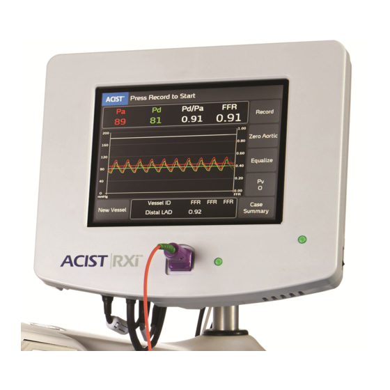
Touchscreen User Interface System Overview Touchscreen User Purpose of the Touchscreen The console touchscreen is the main user interface for the ACIST RXi System Interface and provides the following functionality: • guides the user in system operation • zeros the aortic pressure signal •... - Page 21 FFR recordings. that a new pop-up list with 18 vessel is being pre-defined vessel measured. names or to enter a custom vessel ID. ACIST RXi System User’s Guide | 15 901700-001,01 2019-09 English...
-
Page 22: Navvus® Microcatheter
An electrical interface provides sensor-specific calibration information. The sensor pressure signals are processed by the ACIST RXi System console, which displays Pd/Pa, FFR, Pa, and Pd values in real time. 16 | ACIST RXi System User’s Guide... -
Page 23: Installation
Note This user’s guide is supplied using a variety of methods, including via a provided link to a website, on a CD supplied with the product, etc. For additional copies, contact ACIST Medical. Carefully inspect the contents to ensure everything is included. If any contents are missing, call ACIST Technical Services. -
Page 24: Installation Precautions
To prevent equipment damage, accessory equipment connected to the analog or digital interfaces on the RXi System must be certified to the IEC standard UL/IEC 60601- 1 for medical equipment. Any person who connects equipment to the input or output signal port is configuring a medical system. -
Page 25: Installation Procedures
Installation The ACIST RXi System installation includes the following procedures: Procedures • How to mount the system on a bed rail or an ACIST CVi® Injector • How to connect the ACIST RXi System to the hospital’s hemodynamic system •... - Page 26 7. Connect the power cord to an AC mains power source. The power supply must be positioned to provide easy access to either or both ends of the line power cable for disconnection from mains power. 20 | ACIST RXi System User’s Guide 901700-001,01 2019-09 English...
- Page 27 Mounting the ACIST RXi® System to the ACIST CVi® Injector with the Pivoting Mount System The Pivoting Mount System is used to attach the ACIST RXi System onto the ACIST CVi Injector with or without the optional extension arm as shown below.
- Page 28 4. Attach the pivot bracket or the optional extension arm to the adapter pin. 5. Turn the knob on the pivot bracket or the extension arm clockwise to tighten. 22 | ACIST RXi System User’s Guide 901700-001,01 2019-09 English...
-
Page 29: Connect The Acist Rxi® System To The Hospital's Hemodynamic System
Connect only to certified hemodynamic systems that have no more than 36 VDC output voltage. 4. Connect the other end of the RXi aortic pressure cable to the round port (the one closest to the power cable) on the bottom of the ACIST RXi System as shown below: ACIST RXi System User’s Guide | 23... - Page 30 Ensure that you have the correct pressure output cable for the hospital’s hemodynamic system. 6. Connect the other end of the RXi pressure output cable to the ACIST RXi System, as shown below: 24 | ACIST RXi System User’s Guide...
-
Page 31: Zero The Aortic Pressure On The Acist Rxi® System
Installation Installation Procedures Zero the Aortic Pressure on the ACIST RXi® System To ensure that the hemodynamic monitoring system is reading a zero value: • Turn on power to the system. (Refer to page 30 for instructions.) • With the stopcock at the midaxillary position, open the stopcock to expose the hemodynamic sensor to atmospheric pressure at the patient midaxillary position. -
Page 32: Enter The Facility Name And Lab Id (Optional)
You may enter or change the Facility Name and Lab ID information at any time, but ACIST Medical Systems recommends that you do this during system installation. Instructions for using these options are provided in Section 6, System Information and Settings. -
Page 33: Perform Pa Scaling
After zeroing the aortic pressure, Pa scaling must be performed if the value on the hemodynamic system is different from the Pa value that appears on the RXi touchscreen. If the two values are equal or within ±1 mm Hg, it is not necessary to perform this procedure. - Page 34 Installation Procedures Installation Note If the Pa value on the RXi system no longer equals the value on the hemodynamic system, this procedure must be repeated. Note If the RXi System is connected to a different hemodynamic system, this procedure may need to be repeated.
-
Page 35: Basic Operating Procedures
CAUTION Ensure aortic pressure is correctly set to zero on the RXi System. Always verify the Pa value is zero on the hemodynamic system when zeroing the RXi Pa signal. Only qualified medical professionals may use the ACIST RXi System. User vigilance is required at all times when using the system. -
Page 36: Start The Acist Rxi System
ACIST CVi® Injector. 2. Turn on the system: • Facing the RXi console, use the switch on the right side of the unit to turn on the ACIST RXi System. ON power Off power •... -
Page 37: Verify That The Aortic Pressure Is Zero
Aortic CAUTION Pressure is Ensure aortic pressure is correctly set to zero on the RXi System. Always verify that the Pa value is zero. Zero If the system has been set up as a mobile device, you must zero the aortic pressure signal before each case. -
Page 38: Identify The Patient Id And The Vessel Id For The Case
Basic Operating Procedures Identify the Patient ID To associate a Patient ID with the case, provide a Patient ID using the ACIST Patient ID and the menu. For detailed instructions, refer to Enter a Patient ID on page 64. Vessel ID for the... -
Page 39: Unpack And Prepare The Navvus® Microcatheter
Prepare the the need for formal training in the use of the Navvus MicroCatheter and Navvus® the ACIST RXi System. The techniques and instructions provided here do MicroCatheter not represent ALL medically acceptable protocols, nor are they intended as a substitute for the physician’s experience and judgment in treating any specific... - Page 40 Using the same hand and while still holding the purple handle and orange coil, finally grasp the dispenser coil. 7. Place the dispenser coil and the handle assembly cable in the sterile field. Ensure the handle assembly does not get wet. 34 | ACIST RXi System User’s Guide 901700-001,01 2019-09 English...
- Page 41 When manipulating the Navvus MicroCatheter, avoid creating a knot in the cable. The Navvus MicroCatheter pressure sensor is automatically zeroed when the handle assembly is inserted into the ACIST RXi System console. Therefore, the tip should be outside the patient when this handle assembly is inserted into the system console.
- Page 42 10. Using sterile technique, remove the Navvus MicroCatheter from the dispenser coil and inspect it for any damage or kinks. If damage or kinks exist, discard the microcatheter and use another. 36 | ACIST RXi System User’s Guide 901700-001,01 2019-09 English...
-
Page 43: Deliver The Navvus® Microcatheter, Equalize Signals, And Enter Venous Pressure
3. On the guide catheter, tighten the Tuohy Borst adapter. Failure to do so may result in a false low aortic pressure reading. 4. Advance the Navvus MicroCatheter over the guidewire that is already in place in the distal vasculature. ACIST RXi System User’s Guide | 37 901700-001,01 2019-09 English... - Page 44 • Flush the guide catheter with saline solution. • Verify that the Pa displayed on the ACIST RXi System matches the reading on the hemodynamic monitor. • Press the button.
- Page 45 Deliver the Navvus® MicroCatheter, Equalize Signals, and Enter Venous Pressure 7. Review and adjust the venous pressure value if necessary. (The default value for the venous pressure on the ACIST RXi System is 0 mmHg.) All displayed calculations of resting Pd/Pa and FFR include a correction...
-
Page 46: Detection Of Broken Navvus® Microcatheter
Warning! Catheter malfunction detected. Stop procedure immediately and replace catheter with a new one. The alarm continues to sound and the message displayed until the defective Navvus MicroCatheter is disconnected. 40 | ACIST RXi System User’s Guide 901700-001,01 2019-09 English... -
Page 47: Record The Ffr For The First Vessel
Record and the FFR value represents the resting Pd/Pa. 5. Administer Adenosine (or another vasodilator) and press the Record button before or during maximum hyperemia. Press Record ACIST RXi System User’s Guide | 41 901700-001,01 2019-09 English... - Page 48 If you press recorded values are added to the Vessel ID display area, Save as shown in the example below (up to three FFR recording values can be displayed in this area): 42 | ACIST RXi System User’s Guide 901700-001,01 2019-09 English...
- Page 49 10 recordings have been saved. Note The system saves 10 seconds of data prior to and after the location selected when the Save button is pressed. ACIST RXi System User’s Guide | 43 901700-001,01 2019-09 English...
-
Page 50: Record The Ffr For Another Vessel
JPG format. The Patient ID is stored only while the current Navvus MicroCatheter is connected. Data exported after the micocatheter is disconnected will not include the Patient ID. 44 | ACIST RXi System User’s Guide 901700-001,01 2019-09 English... -
Page 51: Shutting Down The Acist Rxi® System
Basic Operating Procedures Shutting Down the ACIST RXi® System Shutting Down Power Off Shut down the ACIST RXi System by using the switch on the right side of the the ACIST RXi® unit. System Power ON/OFF Switch ON power OFF power ACIST RXi System User’s Guide | 45... - Page 52 Basic Operating Procedures This page intentionally left blank. 46 | ACIST RXi System User’s Guide 901700-001,01 2019-09 English...
-
Page 53: System Information And Settings
About the ACIST Menu System Information and Settings About the ACIST The ACIST menu provides access to system information, system settings, and menu options. These allow the user to view and/or adjust the following Menu settings, or to perform the following tasks: •... - Page 54 About the ACIST Menu System Information and Settings When you press the ACIST logo on the main screen, the ACIST menu is displayed: Press the ACIST logo to view the ACIST menu ACIST menu 48 | ACIST RXi System User’s Guide...
-
Page 55: System Information
To view the system software version and the system date and time, press Information ACIST > System Information. The System Information pop-up window appears as shown below. Note that the Software Version displayed on your system will not match the one shown here. -
Page 56: System Settings
System Settings System Information and Settings System Settings The ACIST Main Menu provides the System Settings submenu: Note These settings cannot be adjusted while the system is recording the FFR. All saved system settings are automatically restored at system startup. -
Page 57: Change The Language Displayed In The System Software
System Settings Change the Language Displayed in the System Software Press ACIST > System Settings > Language to display the language options of the system software. Use the Language pop-up window, (shown below), to view or change the language of the software user interface. -
Page 58: Adjust The Date Setting
The current date is displayed in the Date/Time field of the System Information pop-up window. To adjust the date, press ACIST > System Settings > Date. Use the plus (+) and minus (-) buttons to adjust the Month, Day, and/or Year... -
Page 59: Adjust The Time Setting
Information pop-up window. The time is based on a 24-hour clock (00:00 to 23:59, with 00:00 representing 12 a.m.) Note The RXi System time is not adjusted automatically for daylight savings time. Use the plus (+) and minus (-) buttons to adjust the Hour and Minute settings, then press... -
Page 60: Enter Or Modify The Facility Name
Enter or Modify the Facility Name To associate a Facility Name, such as the hospital’s name or hospital’s ID number, with an FFR patient recording case, press ACIST > System Settings > Facility Name. The Facility Name pop-up keyboard appears as shown below: Use the keyboard to enter the Facility Name. -
Page 61: Lab Id, Mobile Or Stationary
System Information and Settings System Settings Lab ID, Mobile or Stationary Press ACIST > System Settings > Lab ID submenu to view the Lab ID settings screen, as shown below: Lab ID Current Pop-up Lab ID keyboard setting Icon Press Mobile or Stationary to select the desired mode depending on the method of installation of the ACIST RXi®... -
Page 62: Enter Or Modify A Lab Id
Mode When you have finished entering the Lab ID, press to close the Lab ID Enter pop-up keyboard or press the in the upper right corner to close without saving. 56 | ACIST RXi System User’s Guide 901700-001,01 2019-09 English... -
Page 63: Monitor Output Sensitivity Setting
Use the arrow buttons as needed to scroll through the study dates, as well as the list of studies. Monitor Output Sensitivity Setting Contact your ACIST Service Representative for assistance in adjusting the Monitor Output Sensitivity setting. This setting is adjusted at installation to match the system output voltage to the hospital’s hemodynamic monitor, and should not be changed. -
Page 64: Adjust The Audio Volume
Press the corresponding radio button to set button tones to or to Touchscreen Calibration To recalibrate the console panel touchscreen press ACIST > System Settings > Touchscreen Calibration and perform the following steps: 1. Touch the calibration target on the screen to start the four-point calibration. -
Page 65: Adjust The Waveform Settings
System Information and Settings Adjust the Waveform Settings Adjust the The Waveform Settings option on the ACIST Main Menu provides a submenu of waveform configuration options: Waveform Settings ACIST RXi System User’s Guide | 59 901700-001,01 2019-09 English... -
Page 66: Adjust The Number Of Heartbeats Used For Mean Pressure Calculation
Adjust the Number of Heartbeats Used for Mean Pressure Calculation To change the number of heartbeats used to calculate the mean pressure, press ACIST > Waveform Settings > Mean Pressure Calculation. The default setting is 3 heartbeats. In the case of intracoronary administration of the vasodilator, the default setting of 3 heartbeats is recommended. -
Page 67: Adjust The Screen Sweep Speed
Sweep speed is the range of hemodynamic waveform speeds selected by the user. Press ACIST > Waveform Settings > Sweep Speed to view the Sweep Speed pop-up window enabling you to adjust the sweep speed in the waveform display area of the screen. Sweep speed options include 5, 10, 15, or 20 mm/s. -
Page 68: Adjust The Graph Scale Maximum
Cancel Pa Scaling Press ACIST > Waveform Settings > Pa Scaling to view the Pa Scaling pop- up window. This window enables you to perform Pa Scaling (if required). If the Pa value displayed is equal to or within ± 1 mm Hg of the Pa value on the hemodynamic system, it is not necessary to perform Pa scaling (press to exit). -
Page 69: Restore The System Defaults For The Waveform Display
Adjust the Waveform Settings Restore the System Defaults for the Waveform Display Press ACIST > Waveform Settings > Restore Defaults to view the Restore Defaults pop-up window. This window enables you to restore all the waveform display parameters (mean pressure calculation, sweep speed, and graph scale maximum), as well as venous pressure, to the factory default settings. -
Page 70: Create A Patient Id
Create a Patient To associate a patient ID such as the patient’s name or hospital ID number with a patient’s case, press ACIST > Patient ID. The Patient ID pop-up keyboard appears as shown below: Use the keyboard to enter the Patient ID. Use the buttons listed below to perform the task associated with each button: •... -
Page 71: Zero The Pressure Sensor
Zero the Pressure Sensor Zero the Pressure The Zero Pressure Sensor option is available when the pressure sensor on the Navvus MicroCatheter is connected to the ACIST RXi System and the Sensor microcatheter is extracted from the patient’s body. Press ACIST > Zero... -
Page 72: Summary Of Acist Menu Options
Calculation, Sweep Speed, and Graph Scale Maximum) as well as Venous Pressure Patient ID To enter a patient ID Zero Pressure Sensor To set the current pressure value to zero 66 | ACIST RXi System User’s Guide 901700-001,01 2019-09 English... -
Page 73: Additional Settings
Vessel ID: New Vessel The system displays Vessel1 as the default Vessel ID, as shown in the example below: In this example, the Vessel ID field displays Vessel1. ACIST RXi System User’s Guide | 67 901700-001,01 2019-09 English... - Page 74 Press a Vessel ID from the displayed list to select a Vessel ID and close the pop-up window. Or, press the keyboard icon and create a Vessel ID name as described in the next section. 68 | ACIST RXi System User’s Guide 901700-001,01 2019-09 English...
- Page 75 Following recordings, the Vessel name is also displayed in the Vessel ID field of the main screen and in the Case Summary, as shown below: ACIST RXi System User’s Guide | 69 901700-001,01 2019-09 English...
-
Page 76: Review The Case Summary
USB memory values for up to window. device in JPG 10 Vessel IDs. format. An example of an exported case summary for a Vessel ID is shown below: 70 | ACIST RXi System User’s Guide 901700-001,01 2019-09 English... -
Page 77: Review The Ffr Recording (Ffr Review)
Press Discard Press the Revert Press Save to discard the button to reset to save the recording. the FFR Marker to recording. the original FFR minimum value chosen by the system. ACIST RXi System User’s Guide | 71 901700-001,01 2019-09 English... -
Page 78: Zero The Aortic Pressure
Press to zero the aortic pressure or press to return to the ACIST Cancel RXi System’s main screen. You may be prompted to re-equalize. 72 | ACIST RXi System User’s Guide 901700-001,01 2019-09 English... -
Page 79: Adjust The Venous Pressure
Cancel the ACIST RXi System’s main screen. Note Every new case reverts to the default value, which is zero, unless it has been changed to a different value. ACIST RXi System User’s Guide | 73 901700-001,01 2019-09 English... - Page 80 System Information and Settings This page intentionally left blank. 74 | ACIST RXi System User’s Guide 901700-001,01 2019-09 English...
-
Page 81: Maintenance
Cleaning and Maintenance Maintenance Cleaning and Routine maintenance is required to keep the ACIST RXi® System in good working order. This section provides thorough instructions for performing the Maintenance following: • daily maintenance items • monthly maintenance and inspection items... -
Page 82: Decontamination Procedure
Discard all cleaning materials in accordance with all local, state, and federal regulations, codes, and directives. For decontamination, use a 10% bleach solution. To decontaminate the ACIST RXi System, perform the following tasks: 1. Turn off power to the system. 2. Disconnect the power cord from the main power source. -
Page 83: Daily Cleaning
2. Disconnect the power cord from the main power source. 3. Clean the system console with a soft cloth moistened with warm water. Pay special attention to the system console and power supply where fluids may have dripped. ACIST RXi System User’s Guide | 77 901700-001,01 2019-09 English... -
Page 84: Optional Fiber Optic Cleaning Process
Optional Fiber Optic Cleaning Process To perform this procedure, you will need the Senko Smart Cleaner or equivalent fiber optic cleaning tool and the RXi PIM Door Opener. These can be obtained by contacting your ACIST representative or contacting ACIST Customer Service. - Page 85 7. Clean and disinfect the filament and any portion of the cleaner that potentially came in contact with the PIM assembly. 8. Replace the white adapter cap on the cleaner. 9. Remove the PIM door opener from the PIM assembly. ACIST RXi System User’s Guide | 79 901700-001,01 2019-09 English...
-
Page 86: Monthly Inspection And Maintenance
1. Turn off power to the system. 2. Disconnect the power cord from the main power source. 3. Inspect the ACIST RXi System console and power supply. Check the housings for damage. 4. Inspect power cords and cables for cuts, nicks, and openings in the cable insulation. -
Page 87: Troubleshooting And Support
1. Follow instructions in the message displayed on the system console display. If you cannot clear the message, continue to step 2. 2. Turn off power to the ACIST RXi System at the main power supply. 3. Unplug the power cord at the power supply from main power. - Page 88 General Troubleshooting Troubleshooting and Support 8. Resume operation. If you are unable to resolve a problem or if you have any problems or concerns, contact an ACIST Medical Systems service representative. 82 | ACIST RXi System User’s Guide 901700-001,01 2019-09 English...
-
Page 89: Interpreting Led Indicator Lights
The RXi System is not turned on. On (Green) The RXi System is on and functioning properly. On (Red) The RXi System is in an error state as detected by the system software. ACIST RXi System User’s Guide | 83 901700-001,01 2019-09 English... -
Page 90: Hemodynamic Pressure Monitoring
Perform a saline flush before recording physiological waveforms with the transducer system. When using an ACIST or a third-party hemodynamic transducer, clear all tubing of air to avoid producing an inaccurate reading. Pressure Waveform Accuracy To ensure accurate waveforms, zero the hemodynamic transducer with both the transducer and the stopcock at the midaxillary position. -
Page 91: Power Interruption
Note Interruption If an uninterruptible power supply or battery backup is not used to power the ACIST RXi system, and a power interruption for any length of time is experienced, the RXi system will power on once power is resumed if the power on/off switch remains in the on position. -
Page 92: Interpreting Status Messages
The Status Message area of the window provides user instructions and system status information The following table provides a summary of the status messages, the purpose of each message, and the recommended user response. 86 | ACIST RXi System User’s Guide 901700-001,01 2019-09 English... - Page 93 Select the Equalize button Ready to Equalize Displays when the aortic pressure is connected and zeroed, the pressure on the RXi main screen. The RXi sensor is connected, and the System will then equalize the pressures have not been equalized.
-
Page 94: Color-Coded Pop-Up Messages And Problem Conditions
Color-coded Pop-up Messages and Problem Conditions Troubleshooting and Support Color-coded Pop- The following table describes messages displayed in response to system conditions. All messages in the ACIST RXi System are color-coded as follows up Messages according to their severity: and Problem •... - Page 95 Do not remove USB memory stick. Wait until the software is installed. Exporting case data requires the insertion of Blue Insert a USB memory device into the USB port. a USB memory stick. ACIST RXi System User’s Guide | 89 901700-001,01 2019-09 English...
- Page 96 The software installation completed Blue The software download is complete. Remove the successfully. USB memory device and restart the system. Please remove the USB memory stick and restart the system. 90 | ACIST RXi System User’s Guide 901700-001,01 2019-09 English...
-
Page 97: Glossary
Use the plus (+) or minus (-) buttons to change to a different Month, Day, or Year. Distal Pressure (Pd) Mean arterial pressure distal to the stenosis as measured by the Navvus MicroCatheter. ACIST RXi System User’s Guide | 91 901700-001,01 2019-09 English... - Page 98 It is calculated as FFR = (Pd - Pv) / (Pa - Pv). FFR FFR FFR The RXi Main screen displays the FFR for the last three recordings in the current case. FFR Review Screen...
- Page 99 Glossary Term Definition Mobile Mode In the Mobile mode, the RXi System is set up as a mobile device, which means it is moved from room to room. When used in this manner, the aortic pressure on the RXi must be zeroed at the beginning of every patient case.
- Page 100 Select this option on the ACIST Menu when the Option Navvus MicroCatheter pressure sensor is connected to the RXi System. This option should only be used when the microcatheter pressure sensor is reading atmospheric pressure. Your are prompted to remove the microcatheter from the patient’s body when this option...
-
Page 101: Technical Specifications
Electrical Leakage Current Amount Patient leakage current Less than 10 µA Enclosure leakage current Less than 100 µA Earth leakage current (ground) Less than 500 µA ACIST RXi System User’s Guide | 95 901700-001,01 2019-09 English... -
Page 102: Ul Classification
For UL labeled product: C-UL Classified Mark, Medical Electrical equipment, Classified by Underwriters Laboratories Inc. with respect to electric shock, fire and mechanical hazards only in accordance with IEC 60601-1. 96 | ACIST RXi System User’s Guide 901700-001,01 2019-09 English... -
Page 103: Other Specifications
20 lb (9.1 kg) and cables) Dimensions Component Dimensions System console (without power supply Depth: 3.5 in (8.9 cm) and cables) Width: 10.7 in (27.2 cm) Height: 9.2 in (23.4 cm) ACIST RXi System User’s Guide | 97 901700-001,01 2019-09 English... -
Page 104: Cable Lengths
Input sensitivity Compatible with 20 mmHg/V or 100 mmHg/V Pa signal input Pressure Signal Output Signal Type Specification Output sensitivity 5 uV/V/mmHg nominal scale strain gauge bridge (ANSI/ AAMI BP22) 98 | ACIST RXi System User’s Guide 901700-001,01 2019-09 English... -
Page 105: Clinical Guidance For Use Of Pd/Pa To Ffr Measurements
The importance of resting coronary physiology. J Interv Cardiol. 2018 Oct; 31(5): 588-598. 2. Thackery, Lisa.; Rorke, Becky; Larson, Janet A. Post-hoc analysis of data from the ACIST- FFR clinical study which assessed catheter based interrogation and standard techniques for Fractional Flow Reserve Measurement. -
Page 106: Emc Tables
Voltage fluctuations / Complies — flicker emissions IEC:61000-3-3: 1995 + A1:2008 +A2:2005 * The ACIST RXi System is in compliance with Class A RF emissions when the Ao Interface Box is attached. 100 | ACIST RXi System User’s Guide 901700-001,01 2019-09 English... -
Page 107: Guidance And Manufacturer's Declaration - Electromagnetic Immunity
EMC Tables Guidance and Manufacturer’s Declaration - Electromagnetic Immunity The ACIST RXi System is intended for use in the electromagnetic environment specified below. The user of the system should assure that it is used in such an environment. Immunity Test... - Page 108 If the measured field strength in the location in which the RXi System is used exceeds the applicable RF compliance level above, the RXi System should be observed to verify normal operation. If abnormal performance is observed, additional measures may be necessary, such as re-orienting or relocation of the RXi System.
-
Page 109: Criteria Definitions
Recommended Separation Distances Between Portable and Mobile RF Communications Equipment and the ACIST RXi® System The ACIST RXi System is intended for use in an electromagnetic environment in which radiated RF disturbances are controlled. The customer or user of the system can help prevent electromagnetic... - Page 110 RF emissions are very low and are not likely to cause any interference in nearby electronic equipment. RF Emissions Conducted Class B * The ACIST RXi® System is in compliance with Class A RF emissions when the Ao Interface Box is attached. 104 | ACIST RXi System User’s Guide 901700-001,01 2019-09 English...
-
Page 111: Limited Warranty
ACIST product. The foregoing is the sole warranty of ACIST. Any part or component of the ACIST RXi System that is judged to be covered under this warranty by ACIST during the warranty period will be repaired or replaced by ACIST at its option and its expense. - Page 112 SPECIFIED, EVEN IF ACIST SHALL HAVE BEEN ADVISED OF THE POSSIBILITY OF SUCH DAMAGES. IT IS REQUIRED THAT THE ACIST PRODUCT BE OPERATED BY OR UNDER THE IMMEDIATE, DIRECT SUPERVISION OF A LICENSED DOCTOR OR OTHER LICENSED HEALTH CARE PROFESSIONAL QUALIFIED TO USE THE PRODUCT AND PERFORM THE PROCEDURE.
-
Page 113: Appendix: Ao Interface Box
Ao (aortic) input from transducers that would otherwise be connected to the hemodynamic system. Note With the Ao Interface Box attached, the RXi System is in compliance with Class A RF emissions. Indications for Use/Intended Use The RXi Ao Interface Box is indicated for use with the RXi System in order to receive aortic pressure input from transducers that are connected to: •... - Page 114 • Hemodynamic systems where the output channels are dedicated to other cath lab equipment The Ao interface box is intended to connect to the transducer, RXi, and the hemodynamic system. 108 | ACIST RXi System User’s Guide 901700-001,01 2019-09 English...
-
Page 115: Option 1: Installation Of Ao Box On The Rxi Console
Appendix: Ao Interface Box EMC Tables Option 1: Installation of Ao Box on the RXi Console Using a Phillips head screwdriver, remove the two screws on the right side of the console Vesa mount. Position the mounting holes on the Ao Box assembly bracket over the holes in the RXi mount flange and reattach the screws. - Page 116 Gray Connector To Transducer 2. Connect the other end of the cable to the RXi Ao input connector as shown in the illustration above. Push the connection until it clicks to lock it in place. 3. Pull gently on each end of the cable to ensure they are fastened securely.
-
Page 117: Option 2: Ao Interface Box Installed With Remote Mounting Bracket
An alternative method of installing the Ao Interface Box is to attach it to existing cath lab equipment. Remove Bracket A from the Ao Interface Box that is connecting the Ao Interface Box to the RXi console by removing the two screws as illustrated below. - Page 118 2. Connect the female end of this cable to the BNC connector (#1) on the short cable (PN 301764). Connect the other end of the short cable to the RXi Ao input connector as shown in the above illustration. Connect remaining cables as described in the previous section, “Cable Connections to Ao Interface Box”.
-
Page 119: Calibration
Appendix: Ao Interface Box EMC Tables Calibration 1. Ensure that both the hemo system and the RXi system are powered on. Confirm that the RXi System is set to the Mobile mode. Refer to “System Settings” in Section 6 System Information and Settings. - Page 120 EMC Tables Appendix: Ao Interface Box 9. If the RXi system is not reading 100 mmHg while 100 mmHg is supplied to the transducer, use the Pa Scaling function on the RXi software to adjust the signal gain up or down to match 100 mmHg. Refer to “Perform Pa Scaling”...
-
Page 121: Performing A Case
3. Close the stopcock. 4. Continue the case as described in Section 5 Basic Operating Procedures. CAUTION Whenever the hemo system is “zeroed,” ensure the stopcock is open and actively zero RXi using the Zero Aortic button. Cleaning and Maintenance Routine inspection is required to keep the Ao interface box in optimal working condition. - Page 122 Appendix: Ao Interface Box This page intentionally left blank. 116 | ACIST RXi System User’s Guide 901700-001,01 2019-09 English...
- Page 124 ACIST Medical Systems, Inc. 7905 Fuller Road Eden Prairie, MN 55344 USA 901700-001,01 2019-09 English...
Need help?
Do you have a question about the RXI and is the answer not in the manual?
Questions and answers