
Related Manuals for ACIST CVi


Summary of Contents for ACIST CVi
- Page 1 ACIST | CVi® Contrast Delivery System User’s Guide Bracco Group 901418-003,01 2019-08 English (USA)
- Page 2 ©2019 ACIST Medical Systems, Inc. All rights reserved. The written and graphic product descriptions in this manual were effective at the time of printing. ACIST Medical Systems, Inc. reserves the right to change specifications and designs without prior notification. ACIST, ACIST | CVi, and AngioTouch are registered trademarks of ACIST Medical Systems, Inc.
-
Page 3: Table Of Contents
Standby . . . . . . . . . . . . . . . . . . . . . . . . . . . . . . . . . . . . . .46 English (USA) | 3 ACIST | CVi® System User's Guide 901418-003,01... - Page 4 Frequently Asked Questions . . . . . . . . . . . . . . . . . . .65 Troubleshooting the CVi System . . . . . . . . . . . . . . .67 Air Column Detected .
-
Page 5: Introduction
The Manifold Kit and AngioTouch® Hand Controller Kit must be discarded after each patient procedure. The ACIST | CVi® Contrast Delivery System is to be used only by and under quasi-continuous supervision of trained health care professionals in an appropriate licensed health care facility, in a room designated for radiological procedures that involve intravascular administration of a contrast agent. -
Page 6: Aseptic Technique
Sterile openings must be handled with care to ensure contact with only sterile Technique connections or a disinfecting cap. The use of gloves is preferred but not required. About This User’s This User’s Guide provides instructions for setting up and using the CVi system. It includes the following sections: Guide Section Purpose... -
Page 7: Manual Conventions
Cautions alert the user to a possible hazard that may result in equipment damage or personal injury. WARNING Warnings alert the user to a possible hazard that can cause serious injury or death. English (USA) | 7 ACIST | CVi® System User's Guide 901418-003,01 2019-08... - Page 8 Introduction This page intentionally left blank. 8 | English (USA) 2019-08 901418-003,01 ACIST | CVi® System User's Guide...
-
Page 9: Warnings, Cautions, And Symbol Definitions
Symbol Definitions Symbol Definitions Read this entire user guide prior to using the CVi system and patient kits to ensure proper understanding and use. Operate the device only in accordance with this user guide to ensure safe and effective use. -
Page 10: Disconnect Before Flushing Air
Cleaning • To avoid the risk of electric shock, and to prevent damage to the CVi system, always disconnect it from line power before cleaning. • Do not use excessive water when cleaning. -
Page 11: Closed Stopcock
Shock Hazard Hazardous voltage exists within the CVi system. To avoid the risk of electric shock, only trained, qualified personnel should service the CVi system. Disconnect the system from the power source before service. Do not touch the pins on the connectors or the cables. -
Page 12: System Messages
Safe Use of Equipment • No modification of equipment is allowed. • The CVi system may only be interfaced with X-ray equipment that is certified to be in compliance with IEC 60601-1, third edition. • To avoid the risk of electric shock, this equipment must only be connected to a supply mains with protective earth ground. -
Page 13: Cautions
Cautions Cautions The following precautions refer to hazards that could result in injury to the patient or user or damage to the CVi system or other equipment. Read this section carefully. Accessories For proper operation and to ensure equipment compatibility, use only accessories and options provided or specified by ACIST Medical Systems for use with the CVi system. -
Page 14: Excessive Injections
Leakage Current If the chassis leakage current is above 100 µA, do not use the CVi system. Line Power Before connecting the CVi system to an electrical outlet, check the power source for proper voltage and frequency. -
Page 15: Preventive Maintenance
Training All qualified personnel who will be operating the CVi system should be trained by a certified representative of ACIST Medical Systems. X-Ray Cable... -
Page 16: Symbol Definitions
Symbol Definitions 2 Warnings, Cautions, and Symbol Definitions Symbol The following symbols are used on the CVi system, patient kits, and throughout this manual: Definitions Symbol Definition Manufacturer, Date of manufacture Use-by date Batch code Catalog number Serial number Sterilized using ethylene oxide... - Page 17 Federal (USA) law restricts this device to sale by Caution: or on the order of a physician. C-UL, US classification mark Do not tip No syringe Warning: explosive material MR Unsafe English (USA) | 17 ACIST | CVi® System User's Guide 901418-003,01 2019-08...
- Page 18 Warnings, Cautions, and Symbol Definitions This page intentionally left blank. 18 | English (USA) 2019-08 901418-003,01 ACIST | CVi® System User's Guide...
-
Page 19: System Description
AngioTouch® Hand Controller. The hand controller allows variable rate or fixed rate control when dispensing contrast media. When using the variable rate feature, the CVi system allows the user to vary the flow rate from the injector while simultaneously observing the angiographic procedure (for example, on a fluoroscope monitor). -
Page 20: System Hardware
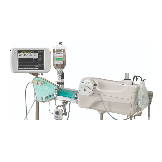
System Hardware 3 System Description System Hardware The CVi system, installed on a pedestal cart or bed rail, includes three main hardware components: • Power supply • Injector head • Control panel System hardware also includes the following components: • Power and communication cables •... -
Page 21: Power Supply
System Hardware Power Supply The power supply is the only connection to mains power and provides power to all subsystems of the CVi system. The power supply provides a data interface connection to some X-ray imaging systems. Injector head Connection... -
Page 22: Injector Head
• On a movable pedestal cart, with the control panel mounted onto the injector head. • On a bed rail, with the control panel mounted onto the injector head. • On a bed rail, with the control panel mounted separately. 22 | English (USA) 2019-08 901418-003,01 ACIST | CVi® System User's Guide... - Page 23 3 System Description System Hardware Control Panel The control panel provides the main user interface for the CVi system. The main features of the control panel are as follows: • provides user prompts throughout the setup procedure. During Touchscreen operation, the touchscreen provides status information, alert messages, and controls for configuring injection parameters and operation status.
-
Page 24: Audible Indicators
Pressure Allows setting the pressure parameter, which is the maximum allowable injection pressure. If the injection pressure approaches this limit, the CVi system will either adjust the flow rate or stop the injection. 24 | English (USA) -
Page 25: Rise Time
Select Injection Allows selecting the desired injection type. The options shown will differ based on whether the CVi system is in cardiac procedure mode or peripheral procedure mode. Peripheral Mode... - Page 26 Touchscreen Functions and Sample Injection Images 3 System Description 26 | English (USA) 2019-08 901418-003,01 ACIST | CVi® System User's Guide...
- Page 27 3 System Description Touchscreen Functions and Sample Injection Images Peripheral Mode English (USA) | 27 ACIST | CVi® System User's Guide 901418-003,01 2019-08...
-
Page 28: Patient Kits
System messages and alerts are displayed in this area of the screen. Patient Kits Before the CVi system is used, the patient kits are loaded onto the injector. The system is to be used only with ACIST-provided patient kits, and only those kits that are intended for use with the CVi system. -
Page 29: Bt2000 Manifold Kit
AT P54 and AT P65 AngioTouch Kits The kit includes an ergonomic AngioTouch hand controller, a 3-way high pressure stopcock with rotating end, and patient tubing. English (USA) | 29 ACIST | CVi® System User's Guide 901418-003,01 2019-08... -
Page 30: A2000 Syringe Kit
Disinfecting caps may differ in color and shape. Disinfecting caps contained within the kit should be used according to the Instructions for Use that accompany the kit. 30 | English (USA) 2019-08 901418-003,01 ACIST | CVi® System User's Guide... -
Page 31: Setup
C. Patient tubing Syringe chamber D. Air column detect sensor K. Saline tubing E. Manifold L. Contrast container hanger F. Pressure transducer M. Saline bag hanger G. Saline pump English (USA) | 31 ACIST | CVi® System User's Guide 901418-003,01 2019-08... -
Page 32: Setup Overview
After the system power is switched on, the control panel on the CVi system will provide guidance during the setup procedure by displaying onscreen prompts. -
Page 33: Prepare The Contrast Container
X-ray system integration not X-ray system integration available available After selecting the procedure type, the CVi system will perform a 60 second calibration routine. 4. Open the syringe chamber on the injector head by pulling on the white syringe door pin. -
Page 34: Load The Syringe Assembly
Contamination of either luer presents a risk of serious patient injury due to infection. Aseptic technique must be employed. If suspected contamination has occurred, replace the affected kit or kits. 34 | English (USA) 2019-08 901418-003,01 ACIST | CVi® System User's Guide... - Page 35 6. Hold the container at an angle away from the contrast sensor with the septum facing up. Insert the contrast spike into the septum of the contrast container. Ensure the air vent on the contrast spike is open. English (USA) | 35 ACIST | CVi® System User's Guide 901418-003,01 2019-08...
- Page 36 No contrast. • If the air vent and the white slide clamp are not open, the system may produce an error stating No contrast. 36 | English (USA) 2019-08 901418-003,01 ACIST | CVi® System User's Guide...
-
Page 37: Load Saline Tubing Assembly
Note A hemodynamic monitoring cable is required. The cable type is dependent upon the type of monitoring equipment used. Contact ACIST Medical to obtain the correct transducer interconnect cable. English (USA) | 37 ACIST | CVi® System User's Guide 901418-003,01... - Page 38 6. Position both black tubing guides all the way to the top, then center the tubing in the pump. Verify that the teeth of the tubing guides are centered over the tubing. 38 | English (USA) 2019-08 901418-003,01 ACIST | CVi® System User's Guide...
-
Page 39: Purge The Tubing
8. Leave the hand syringe in place until ready to connect it to the patient tubing. 9. Press on the touchscreen. DONE English (USA) | 39 ACIST | CVi® System User's Guide 901418-003,01 2019-08... -
Page 40: Angiotouch
6. Connect the hand controller to the control panel using both luer fittings. Secure them tightly. 7. Calibrate the hand controller following the instructions on the control panel. 40 | English (USA) 2019-08 901418-003,01 ACIST | CVi® System User's Guide... -
Page 41: Connect The Patient Catheter
2. Hold the stopcock and pressure transducer at midaxillary. Before recording pressure waveforms, flush saline through the patient tubing. Contrast in the patient tubing will damp the pressure signal. English (USA) | 41 ACIST | CVi® System User's Guide 901418-003,01 2019-08... - Page 42 Setup This page intentionally left blank. 42 | English (USA) 2019-08 901418-003,01 ACIST | CVi® System User's Guide...
-
Page 43: Perform An Injection
4. (Optional) Press on the control panel INJECT DELAY X-RAY DELAY to modify how the CVi system interacts with a connected X-ray imaging system. • Inject Delay – Delays the start of contrast injection by the specified number of seconds. -
Page 44: Arm The Injector
Automatic and Manual Refills When the amount of contrast in the syringe is not enough for the next injection, the CVi system will automatically refill the syringe from the contrast container. To stop the system from refilling the syringe, press STOP REFILL the control panel. -
Page 45: Perform Contrast Purge
• The hand controller may be disabled with some X-ray imaging systems. • X-ray imaging may be initiated by the CVi system with some X-ray imaging systems. • X-Ray Sync is available only with peripheral mode injections. Perform Contrast 1. -
Page 46: Standby
Standby 5 Perform an Injection Standby The Standby button immediately suspends operation of the CVi system. Press button once to place the CVi system into Standby mode. When STANDBY the CVi system is in Standby mode, all functions are paused. -
Page 47: End A Case
2. The system displays the number of cases for which the syringe has been used. Press to start a new case with the current syringe. 3. Close the white slide clamp on the contrast container tubing. English (USA) | 47 ACIST | CVi® System User's Guide 901418-003,01 2019-08... -
Page 48: If Using A New Syringe
8. Remove and discard the syringe. 9. Close the syringe chamber. 10. Press RESTART. 11. Follow the instructions beginning with Load the Syringe Assembly on page 34. 48 | English (USA) 2019-08 901418-003,01 ACIST | CVi® System User's Guide... -
Page 49: If Final Case
If Using a New Syringe on 3. Press page 48. Press to use the syringe for one additional emergency case. English (USA) | 49 ACIST | CVi® System User's Guide 901418-003,01 2019-08... - Page 50 If the white slide clamp is closed, the system may display Manifold Valve Open or Syringe Valve Open indicators or messages. 16. Continue the setup procedure at Load Saline Tubing Assembly on page 37. 50 | English (USA) 2019-08 901418-003,01 ACIST | CVi® System User's Guide...
-
Page 51: Supplementary Procedures
A disinfecting cap must be properly placed onto the multi-use syringe before cleaning. After every patient procedure check to see if any contrast or other fluids spilled on the CVi system. If so, use the following procedure to clean and disinfect the CVi system. English (USA) | 51 ACIST | CVi®... -
Page 52: Cleaning / Disinfection Procedure
7 Supplementary Procedures Cleaning / Disinfection Procedure If the CVi system needs to be cleaned of biohazards such as blood or other bodily fluids, ACIST recommends using DisCide ULTRA as a cleaning and disinfection agent. Wear protective gloves. Discard all materials used to decontaminate the system in accordance with all local, state, and federal regulations, codes, and directives. - Page 53 Allow the material to remain moistened for a minimum of 1 minute prior to removal per the user instructions. Syringe door pin English (USA) | 53 ACIST | CVi® System User's Guide 901418-003,01 2019-08...
-
Page 54: Monthly Inspection
Replace if damaged. • Check to make sure that the bed rail mount (if applicable) is securely fastened. • Check for wheel damage on the CVi system cart (if applicable). Annual For optimal performance, an ACIST Medical Systems representative should perform routine annual maintenance. -
Page 55: Transfer The Injector Head
(bed rail or pedestal cart). 4. Tighten the lock knob. Make sure the system is locked and secure. English (USA) | 55 ACIST | CVi® System User's Guide 901418-003,01 2019-08... -
Page 56: Cabling
Cabling 7 Supplementary Procedures Cabling Cables between CVi system components are normally connected during installation by an approved representative or distributor. If it becomes necessary to connect the cables between components because the system was moved or serviced, follow the instructions below. -
Page 57: Connect The X-Ray Interface Cable On
X-ray imaging system is properly configured before the input cable is connected to the CVi system. Connect the imaging interface cable from the injector head directly to the X-ray imaging system. To X-ray imaging system English (USA) | 57 ACIST | CVi® System User's Guide 901418-003,01 2019-08... -
Page 58: Connect The X-Ray Interface Cable On Siemens-Ready Systems (Optional)
To avoid damaging the X-ray imaging equipment, make sure the connector on the X-ray imaging system is properly configured before the input cable is connected to the CVi system. 58 | English (USA) 2019-08 901418-003,01 ACIST | CVi® System User's Guide... -
Page 59: Plug In The Power Supply
Plug In the Power Supply Connect the power cord between the power supply and a wall outlet. The appropriate medical grade power cable is supplied with the CVi system. In order to prevent voltage differential between medical equipment, an equipotential cable may be required. Ground equalization can be established by connecting the equipotential cable to either the equipotential lug or the thumb screw on the power supply. -
Page 60: Mount The Power Supply On A Cart (Optional)
1. Loosen the power supply clamp on the pedestal cart. Supply on a Cart 2. Place the power supply in the clamp at an angle. (Optional) 3. Rotate the power supply into the clamp. 60 | English (USA) 2019-08 901418-003,01 ACIST | CVi® System User's Guide... -
Page 61: Recalibrate Control Panel Screen
Change the Display Language Display Language During system startup, the CVi system presents a list of languages. Press the and Pressure button next to the desired language. If no language selection is made within 5 seconds, the system defaults to the last selected language. -
Page 62: Calculate Parameters From Patient Weight
Calculate Parameters from Patient Weight 7 Supplementary Procedures Pressure Units When a language other than English (US) is selected, the CVi system presents a second screen with a choice of pressure units (psi or kPa). Press the button next to the desired pressure unit. -
Page 63: Change Color Scheme
Scheme always changes the color scheme. System Info Press to cycle through CVi system data: SYSTEM INFO • HW Configuration – Board and control panel IDs • SW Configuration – System software and firmware versions • Current Session Info – Case number and patient manifold valve (pValve) failures •... - Page 64 Supplementary Procedures This page intentionally left blank. 64 | English (USA) 2019-08 901418-003,01 ACIST | CVi® System User's Guide...
-
Page 65: Troubleshooting
Contrast is leaking from the syringe or contrast spike. Why? • Close the white slide clamp before changing a patient kit. • Press the button and check the connection of the contrast spike. Standby English (USA) | 65 ACIST | CVi® System User's Guide 901418-003,01 2019-08... - Page 66 • Lower the rear tubing guide so that it stops the saline tubing from advancing without crimping the saline tubing. • Use only saline tubing from ACIST Medical Systems. The performance of other tubing cannot be guaranteed. Why is the hand controller not working? •...
-
Page 67: Troubleshooting The Cvi System
• The white slide clamp may be closed, blocking the flow of contrast. • The air vent on the contrast spike may be closed. • There may be air bubbles trapped in the contrast tubing. English (USA) | 67 ACIST | CVi® System User's Guide 901418-003,01 2019-08... -
Page 68: Hand Controller Calibration Failed
• The pressure, flow, or rise time parameters may be configured incorrectly. If the Pressure Limit message appears, it means the configured pressure limit was nearly reached. The CVi system automatically adjusts to keep injection pressure beneath the configured limit by reducing or stopping the flow rate. -
Page 69: Manifold Valve Failed To Close N Times Using Current Syringe
Press START REFILL. There is a gray wire underneath the syringe chamber. This wire may have been disconnected or may need to be cleaned. English (USA) | 69 ACIST | CVi® System User's Guide 901418-003,01 2019-08... -
Page 70: Syringe Valve Open
PURGE SYRINGE. Note Arming the injector will cause the CVi system to automatically purge if necessary. • The white slide clamp above the contrast sensor may be closed. • There is a gray wire underneath the syringe chamber. This wire may have been disconnected or it may need to be cleaned. -
Page 71: Troubleshooting Hemodynamic Issues
ӽ Replace the backplate if it is worn out, cracked, or damaged. When inspecting the backplate, pay special attention to the condition of the membrane and to the rails that hold the transducer in place. English (USA) | 71 ACIST | CVi® System User's Guide 901418-003,01 2019-08... -
Page 72: Procedure
• The manifold valve may be partially open. If it is, press the button Standby on the side of the control panel to pause the CVi system and allow the manifold valve to return to its home position. • Check the patient catheter for the following issues: ӽ... -
Page 73: System Messages
8 Troubleshooting System Messages System Messages The following table lists all of the messages displayed by the CVi system. If the message cannot be cleared, contact an ACIST service representative. Message Recommendation Actuator Calibration Failed Try cycling power to the system. - Page 74 If the problem persists, contact a service representative. Disarm The connected X-ray imaging system has disarmed the CVi system. Consult the X-ray imaging system's instructions to determine how to correct the problem. DISARMED! Arming and disarming the system is controlled by the X-ray imaging system.
- Page 75 If there are no flow restrictions and the error persists, contact a service representative. Interprocessor Ping Error Try cycling power to the system. English (USA) | 75 ACIST | CVi® System User's Guide 901418-003,01 2019-08...
- Page 76 • Make sure that the white slide clamp on the contrast tubing is open. • Replace the patient kit. Motor Speed Incorrect Try cycling power to the system. 76 | English (USA) 2019-08 901418-003,01 ACIST | CVi® System User's Guide...
- Page 77 Press Standby to Release pressure to relieve back pressure on the manifold. Release Trigger for New Injection Release the contrast button on the hand controller to begin a new injection. English (USA) | 77 ACIST | CVi® System User's Guide 901418-003,01 2019-08...
- Page 78 If this alert occurs during setup, the syringe may be faulty and may need to be replaced. This alert can also occur if the syringe valve sensor needs to be cleaned. 78 | English (USA) 2019-08 901418-003,01 ACIST | CVi® System User's Guide...
- Page 79 There is a 20 minute limit for KVO The system automatically stops the KVO function after 20 consecutive minutes as a safety feature. Values Out of Range Try cycling power to the system. English (USA) | 79 ACIST | CVi® System User's Guide 901418-003,01 2019-08...
- Page 80 Troubleshooting This page intentionally left blank. 80 | English (USA) 2019-08 901418-003,01 ACIST | CVi® System User's Guide...
-
Page 81: Specifications
> 20ml/sec. When using 4Fr catheters, flow rate reduction may occur with > 12ml/sec flow rate settings and Pressure Limit may occur with flow rate settings > 15ml/sec. English (USA) | 81 ACIST | CVi® System User's Guide 901418-003,01 2019-08... -
Page 82: Pedestal Cart Dimensions
Pedestal Cart The dimensions of the pedestal cart are as follows: Dimensions Item Dimensions Wheelbase footprint 53.3 × 63.5 cm 21 × 25 in Height 91.4 cm 36 in 82 | English (USA) 2019-08 901418-003,01 ACIST | CVi® System User's Guide... -
Page 83: Weight
+18 °C to +29.4 °C +64 °F to +85 °F Relative humidity 10 % to 85 % non-condensing Atmospheric pressure 70 kPa to 106 kPa 10 psi to 15 psi English (USA) | 83 ACIST | CVi® System User's Guide 901418-003,01 2019-08... -
Page 84: Power Supply
Electrical Leakage < 10 µA for patient connection < 100 µA for chassis Complies with EN/IEC 60601-1, second edition and third edition, Amendment 1. Patient Kits The CVi system uses the following patient kits: Model Number Model Name Uses BT2000 Manifold Kit... -
Page 85: Hemodynamic Transducer
15% pressure transducer bandwidth > 200 Hz Supported The CVi system synchronizes with the following X-ray imaging systems. This table reflects current interface capabilities as of this revision. Please contact the Imaging Systems manufacturer for any updates if your system is not identified here. -
Page 86: Ul Approval
Mode of operation Continuous Note The equipment is not suitable for use in the presence of a flammable anesthetic mixture with air or with oxygen or nitrous oxide. 86 | English (USA) 2019-08 901418-003,01 ACIST | CVi® System User's Guide... -
Page 87: Emc Tables
Guidance and Manufacturer’s Declaration—Emissions The CVi system is intended for use in the electromagnetic environment specified below. The customer or user of the CVi system should ensure that it is used in such an environment. Note The emissions characteristics of this equipment make it suitable for use in industrial areas and hospitals (CISPR 11 Class A). - Page 88 10 EMC Tables Guidance and Manufacturer’s Declaration—Immunity The CVi system is intended for use in the electromagnetic environment specified below. The customer or user of the CVi system should ensure that it is used in such an environment. IEC 60601...
- Page 89 • Portable RF communications equipment (including peripherals such as antenna cables and external antennas) should be used no closer than 30 cm (12 inches) from any part of the CVi system, including cables specified by the manufacturer. Otherwise, degradation of the performance of this equipment could result.
- Page 90 10 EMC Tables Recommended Separation Distances for the CVi System The CVi system is intended for use in the electromagnetic environment in which radiated disturbances are controlled. The customer or user of the CVi system can help prevent electromagnetic interference by maintaining...
-
Page 91: Limited Warranty
ACIST product. The foregoing is the sole warranty of ACIST. Any part or component of the ACIST CVi® System that is judged to be covered under this warranty by ACIST during the warranty period will be repaired or replaced by ACIST at its option and its expense. - Page 92 SPECIFIED, EVEN IF ACIST SHALL HAVE BEEN ADVISED OF THE POSSIBILITY OF SUCH DAMAGES. IT IS REQUIRED THAT THE ACIST PRODUCT BE OPERATED BY OR UNDER THE IMMEDIATE, DIRECT SUPERVISION OF A LICENSED DOCTOR OR OTHER LICENSED HEALTH CARE PROFESSIONAL QUALIFIED TO USE THE PRODUCT AND PERFORM THE PROCEDURE.
- Page 94 ACIST Medical Systems, Inc. 7905 Fuller Road Eden Prairie, MN 55344 USA 901418-003,01 2019-08 ACIST | CVi® System User's Guide English (USA)
Need help?
Do you have a question about the CVi and is the answer not in the manual?
Questions and answers
removing saline bag holder