Table of Contents
Advertisement
Quick Links
SF Series Intelligent Sensor Indicator Manual
For your safety, please read the below content carefully before you use the meter !
Safe Caution
Please read the manual carefully before you use the meter
Please comply with the below important points:
Warning An accident may happen if the operation does not comply with the instruction.
Notice
An operation that does not comply with the instruction may lead to product damage.
The instruction of the symbol in the manual is as below.
An accident danger may happen in a special condition.
Warning
1. A safty protection equipment must be installed or please contact with us for the relative information if the
product is used under the circumstance such as nuclear control, medical treatment equipment, automobile,
train, airplane, aviation, equipment, etc. Otherwise, it may cause serious loss, fire or person injury.
2. A panel must be installed, otherwise it may cause creepage (leakage).
3. Do not touch wire connectors when the power is on, otherwise you may get an electric shock.
4. Do not dismantle or modify the product. If you have to do so, please contact with us first. Otherwise it may
cause electric shock and fire.
5. Please check the connection number while you connect the power supply wire or input signal, otherwise it may
cause fire.
Caution
1. This product cannot be used outdoors. Otherwise the worki ng life of the product will become shorter, or an electric
shock accident may happen.
2. When you connect wire to the power input connectors or signal input connectors, the moment of the No.20 AWG
(0.50 mm2) screw tweaked to the connector is 0.74n.m - 0.9n.m. Otherwise the connectors may be damaged or get fire.
3. Please comply with the rated specification. Otherwise it may cause electric shock or fire, and damage the product.
4. Do not use water or oil base cleaner to clean the product. Otherwise it may cause electric shock or fire.
and damage the product.
5. This product should be avoid working under the circumstance that is flammable, explosive, moist, under sunshine, heat
radiation and vibration. Otherwise it may cause explosion.
6. In this unit it must not have dust or deposit, otherwise it may cause fire or mechanical malfunction.
7. Do not use gasoline, chemical solvent to clean the cover of the product because such solvent can damage it. Please use
some soft cloth with water or alcohol to clean the plastic cover.
1. Model Illustration
SF
□
□□□
□
Features :
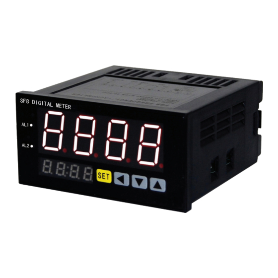
⊙ Dual lines LED display , upper line shows the measure value ,
⊙ Two alarm output
⊙ Universal linear signal and thermocouple signal input
⊙ Easy to operate
T: temperature sensor signal input , Blank :Voltage/ampere input
B:DC 24V auxiliary power supply A:DC 12V auxiliary power supply(should order)
Blank:Without auxiliary power supply
0:Without alarm 2:Two alarm
R:Relay alarm output A:Without alarm
4:48W×48H 6:48W×96H 7:72W×72H 8:96W×48H 9:96W×96H
80:160W×80H(should order) 16:80W×160H(should order)
lower line display measure units.
KKSFE02-A0-1
Advertisement
Table of Contents

Related Manuals for SOMMY SF Series


Summary of Contents for SOMMY SF Series
- Page 1 SF Series Intelligent Sensor Indicator Manual Features : ⊙ Dual lines LED display , upper line shows the measure value , lower line display measure units. ⊙ Two alarm output ⊙ Universal linear signal and thermocouple signal input ⊙ Easy to operate...
- Page 2 2.Ordering Model Input signal Alarm Auxiliary power supply Model DC 0~10V , 4~20mA, DC 0~5V , 0~20mA No Alarm Without DC 0~10V , 4~20mA, DC 0~5V , 0~20mA Two Alarm Output DC 24V/30mA ① A0 T Without TC/RTD,0~50mV,0~400Ω No Alarm Two Alarm Output DC 24V/30mA R2B T...
- Page 3 7. Setting menu Menu Initial Value Setting range Function name Description FL~FH #1 Alarm Value Setting #1 Alarm Value HH: Alarm 1 upper limit HL: Alarm 1 lower limit HH/HL #1 Alarm Mode #1 Alarm Hysteresis 0-1000 #1 Alarm Hysteresis FL~FH #2 Alarm Value #2 Alarm Value Setting...
- Page 4 93.0 100.0 25.0 10.0 10.0 80.0 +0.5 SF7 DIGITAL METER 7:72H*72W +0.5 100.0 117.0 10.0 25.0 84.0 +0.5 45.5 SF8 DIGITAL METER 8:48H*96W +0.5 91.5 122.0 101.0 25.0 10.0 91.0 SF9 DIGITAL METER +0.5 9:96H*96W +0.5 +0.5 80:80H*160W 103 25 +0.5 154.5 SF16 DIGITAL METER...
Need help?
Do you have a question about the SF Series and is the answer not in the manual?
Questions and answers