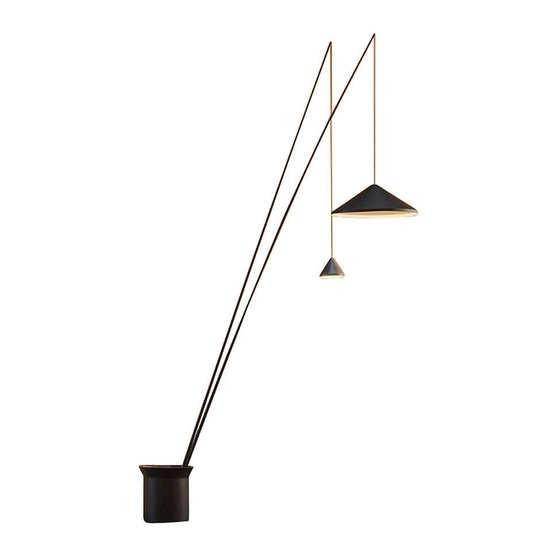
VIBIA North Assembly Instructions Manual
Hide thumbs
Also See for North:
- Assembly instructions manual (33 pages) ,
- Assembly instructions manual (55 pages)
Advertisement
Quick Links
ASSEMBLY INSTRUCTIONS
SUPPLIED MATERIAL
1.
Allen key / Llave allen / Imbußschlüssel
1
Key / Llave / Schlüssel
2
Rod / Caña / Stange
3
Shade / Pantalla / Schirm
4
Base / Base / Fuß
5
6
Counterweight / Contrapeso / Gegengewicht
TECHNICAL SPECIFICATIONS
North
Design by Arik Levy
INSTRUCCIONES DE MONTAJE
MATERIAL SUMINISTRADO
2.
ESPECIFICACIONES TÉCNICAS
3.
5600
5605
2 un.
2 un.
1 un.
1 un.
2 un.
2 un.
2 un.
2 un.
1 un.
1 un.
4 un.
4 un.
MONTAGEANLEITUNG
GELIEFERTES MATERIAL
4.
5.
TECHNISCHE DATEN
6.
Advertisement

Summary of Contents for VIBIA North
- Page 1 North Design by Arik Levy ASSEMBLY INSTRUCTIONS INSTRUCCIONES DE MONTAJE MONTAGEANLEITUNG SUPPLIED MATERIAL MATERIAL SUMINISTRADO GELIEFERTES MATERIAL 5600 5605 2 un. 2 un. Allen key / Llave allen / Imbußschlüssel 1 un. 1 un. Key / Llave / Schlüssel 2 un.
-
Page 2: Important Notice
ASSEMBLY INSTRUCTIONS INSTRUCCIONES DE MONTAJE MONTAGEANLEITUNG IMPORTANT NOTICE: Switch of the mains before installing the lamp. 1. Remove the tour screws (A) from the cover using the supplied Allen key. 2. Remove the cover (B). 3. Grab the carcass (C) tightly and turn to the left following the arrows to loosen, then pull the carcass upwards in order to disassemble. - Page 3 ASSEMBLY INSTRUCTIONS INSTRUCCIONES DE MONTAJE MONTAGEANLEITUNG 4. The base is ready to plug into an electrical current using the Schuko plug (D) attached to the cable. 5. If installation using the cable of existing electrical connection is preferred the removal of the levelling feet (E) is recommended.
- Page 4 ASSEMBLY INSTRUCTIONS INSTRUCCIONES DE MONTAJE MONTAGEANLEITUNG 7. Attach to the floor using the most appropriate screws and plugs for that surface. 8. Undo the nuts and washers (G) from the foundation bolts. 9. Place the four counterweights (H) supplied and affix with the nuts and the washers (G) previously disassembled.
- Page 5 ASSEMBLY INSTRUCTIONS INSTRUCCIONES DE MONTAJE MONTAGEANLEITUNG 10. Position the carcass (C). Place a slight pressure downwards and rotate in such a way that the gold coloured screws of the base are completely within the fastening holes. 11. Through the three slots press the three gold coloured screws (I) using the correct screwdriver.
- Page 6 ASSEMBLY INSTRUCTIONS INSTRUCCIONES DE MONTAJE MONTAGEANLEITUNG 13. Extend the rods. They must be tightened from the sections outwards and rotated to complete, making sure that they are securely fixed. IMPORTANT: As the various sections are being tightened attach the electrical cable that should be introduced at the end.
- Page 7 ASSEMBLY INSTRUCTIONS INSTRUCCIONES DE MONTAJE MONTAGEANLEITUNG Introduce into corresponding slot, and after adjusting the height and angle, tighten with a Phillips screwdriver (J). 16. Adjust the height of the cable to which the shades are connected: To raise pull on the cable from the end of the rod mounted on the base.
- Page 8 ASSEMBLY INSTRUCTIONS INSTRUCCIONES DE MONTAJE MONTAGEANLEITUNG 17. Insert the cable into the groove of the rod holder (K). 18. Assemble the other rod in position as indicated in step 14, and adjust the estimated height of the cables without attaching the shades. 17.
- Page 9 ASSEMBLY INSTRUCTIONS INSTRUCCIONES DE MONTAJE MONTAGEANLEITUNG Affix shades corresponding rods. The drawing indicates the dimensions of the shade and the length of the rod to which it should be attached. 19. Montar las pantallas en la caña que les corresponda. En el dibujo puede ver las dimensiones de la pantalla y la longitud de la caña en la que tiene que ir montada.
- Page 10 ASSEMBLY INSTRUCTIONS INSTRUCCIONES DE MONTAJE MONTAGEANLEITUNG 20. Connect the terminals (L) of the supplied cable and the shade. Make sure that they are completely connected. 21. Turn the element (M) by hand without the use of any tools. In order to complete the action use the key supplied (O).
- Page 11 ASSEMBLY INSTRUCTIONS INSTRUCCIONES DE MONTAJE MONTAGEANLEITUNG 22. WARNING: If necessary the heights of the shades can be adjusted between two people, one holding the shade and the other pulling the cable. 23. Connect the switches (R) to the central core connectors. 22.
- Page 12 ASSEMBLY INSTRUCTIONS INSTRUCCIONES DE MONTAJE MONTAGEANLEITUNG 24. Roll up the excess cable and place it within the base. 25. Plug in the connector from the cover (P) identified with a sticker marked P. 24. Enrollar el cable sobrante y alojarlo en interior de la base 25.
- Page 13 ASSEMBLY INSTRUCTIONS INSTRUCCIONES DE MONTAJE MONTAGEANLEITUNG 26. Position the cover (B). To start with enter at an angle along the opening of the longest rod and then move the rods, if necessary, to coincide with the openings taking care not to scratch.
- Page 14 ASSEMBLY INSTRUCTIONS INSTRUCCIONES DE MONTAJE MONTAGEANLEITUNG 29. Follow steps 29 to 31 inclusive, only if the position of the indicated rod is required. The position of the rod marked with the number 89 can be assembled in an alternative position, in such a way that the angle between the rods is different.
- Page 15 ASSEMBLY INSTRUCTIONS INSTRUCCIONES DE MONTAJE MONTAGEANLEITUNG 31. The cover (B) comes equipped with 6 protective plastic covers (T), protecting the gaps through which the rods must be passed. The protective cover (T) must be removed from the gap through which the rod to be moved will pass and then fitted to the gap remaining where no rod is provided.


Need help?
Do you have a question about the North and is the answer not in the manual?
Questions and answers