Advertisement
Quick Links
Advertisement

Related Manuals for ekwb EK-Quantum Inertia D5 PWM


Summary of Contents for ekwb EK-Quantum Inertia D5 PWM
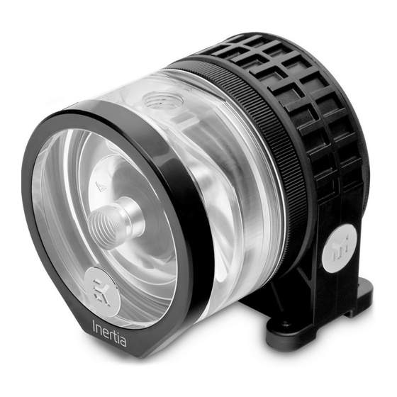
- Page 1 EK-Quantum Inertia D5 PWM PUMP INSTALLATION MANUAL...
- Page 2 EK-Quantum The following instructions are subject to change without Inertia D5 PWM D-RGB notice. Please visit our website at www.ekwb.com for updates. Before you start using this product, please follow the basic guidelines: Carefully read the manual before beginning with the...
-
Page 3: Installing The Pump
INSTALLING THE PUMP MOUNTING MECHANISM Bag content is universal; you may not need every screw. M3 x 12 DIN7984 (2 pcs) M4 x 10 DIN7984 (5 pcs) (ALREADY DONE BY EK) EK-Quantum Inertia 60x3 O-ring Gasket EK-D5 PWM G2 Motor M4 PVC Washers (5 pcs) Protective Sticker (1 pc) Locking Ring... - Page 4 PWM G2 Motor. 6. Take the M3x12 DIN7984 screws and secure the EK- By default, the EK-Quantum Inertia D5 PWM D-RGB D5 PWM G2 Motor to the pump holder. You should ships with a pump holder that can be installed directly use the 2mm Allen Key.
- Page 5 EK-Quantum Inertia D5 PWM D-RGB can be used in any mounting configuration (position) apart from being mounted upside down! Mounting the pump upside down will result in the pump running dry and eventually lead to premature failure of the pump!
- Page 6 M4 x 10 DIN7984 EK recommends using the EK-Loop UNI Pump Reservoir Bracket. Secure the EK-Quantum Inertia D5 PWM D-RGB onto the EK-Loop UNI Pump Reservoir Bracket using the enclosed M4 x 10 DIN7984 screws and M4 PVC washers (as shown in the image).
- Page 7 ATTACHING THE FITTINGS EK recommends using EK-Quantum Torque Fittings with the EK-Quantum Inertia D5 PWM D-RGB series OUTLET pump tops. To ensure the tubes are securely attached to the barb/fitting, please use hose clamps or an appropriate substitute. • It is mandatory to use the correct INLET and OUTLET ports.
-
Page 8: Connecting The Pump
CONNECTING THE PUMP The EK-D5 PWM pump has two following connectors: 1. 4-Pin Molex - Must be connected directly to your PSU at all times as it’s used to power the pump. 2. 4-Pin PWM Fan Connector – Can be connected to your motherboard’s CPU, fan, or designated water pump header, as well as a controller. - Page 9 CONNECTING THE D-RGB LIGHTS Plug the 3-pin connector from the water block’s D-RGB LED light to D-RGB HEADER on the motherboard. The LEDs will work if the pin layout on the header is as follows: +5V, Data, Empty, Ground. Please, ensure that the arrow indicated on the connector is plugged into the +5V line, as indicated on your motherboard.
- Page 10 TESTING THE LOOP To make sure the installation of EK components was successful, we recommend you perform a leak test for 24 hours. When your loop is complete and filled with coolant, connect the pump to a PSU outside of your system. Do not connect power to any of the other components.
-
Page 11: Support And Service
SUPPORT AND SERVICE For assistance please contact: http://support.ekwb.com/ EKWB d.o.o. Pod lipami 18 1218 Komenda Slovenia - EU SOCIAL MEDIA...
Need help?
Do you have a question about the EK-Quantum Inertia D5 PWM and is the answer not in the manual?
Questions and answers