Advertisement
Quick Links
Advertisement

Subscribe to Our Youtube Channel
Related Manuals for ekwb EK-Quantum Kinetic TBE D5 PWM


Summary of Contents for ekwb EK-Quantum Kinetic TBE D5 PWM
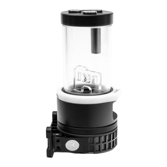
- Page 1 EK-Quantum Kinetic TBE D5 PWM PUMP & RESERVOIR COMBO INSTALLATION MANUAL...
-
Page 2: Assembling The Pump
ASSEMBLING THE PUMP (already done by EK) EK-Quantum Kinetic TBE D5 60x3 O-ring Gasket Locking Ring EK-D5 PWM G2 Motor Pump Holder Screws M3x12 Rubber Damper - 2 -... - Page 3 STEP 1 Install the EK-Quantum Kinetic TBE D5 onto the EK-D5 PWM G2 Motor. Make sure you install the provided 60x3 O-ring gasket. Reseat the gasket if needed. You can rotate the EK-D5 PWM G2 Motor if required. STEP 2 Secure the EK-D5 PWM G2 Motor on the EK-Quantum Kinetic TBE D5 using enclosed Locking Ring.
- Page 4 ALTERNATIVE DAMPER Pyramids must be facing UP STEP 1 - 4 -...
- Page 5 STEP 1 An alternative soft rubber damper is included. If excessive pump vibrations are transmitted through the mounting assembly then this can be used to reduce them further. When replacing the damper, take care that the pyramids face upwards as shown. Use of the soft damper is only recommended when the unit is installed vertically.
- Page 6 USING EK-HD TUBE STEP 1 - 6 -...
- Page 7 EK-Quantum Kinetic TBE D5 reservoir comes pre- installed with a flat anticyclon. If your system suffers from air bleeding problems, if the pump is circulating air or there is excessive vortexing you may replace the anticyclone with the enclosed EK-HD Tube. STEP 1 Insert enclosed O-ring 16x2 into the groove inside center hole and insert enclosed EK-HD Tube.
- Page 8 USING TOP PORT AS INLET Internal Tube EK-Quantum Kinetic TBE D5 - 8 -...
- Page 9 The internal tube, which is already pre-installed with the EK-Quantum Kinetic TBE D5 PWM, can be used for fluid intake in the reservoir. - 9 -...
-
Page 10: Installing The Reservoir
INSTALLING THE RESERVOIR Computer chassis metal plate EK-Quantum Kinetic TBE D5 M4x10 Screw Pump Holder Plastic Washer - 10 -... - Page 11 By default the EK-Quantum Kinetic TBE D5 ships with a pump holder that can be installed directly to the computer chassis. If there are no appropriate mounting holes available: user may need to drill 4 (four) Ф5 mm holes through the metal chassis using an electric power drill.
- Page 12 EK recommends users to find an appropriate position in your computer chassis to install the EK-Quantum Kinetic TBE D5 assembly. It can be mounted in any orientation except with the pump at the top. To successfully install the EK- Quantum Kinetic D5 pump/reservoir assembly please complete the following steps: - 12 -...
- Page 13 STEP1 Find an appropriate position for the unit inside (or perhaps outside) of your computer chassis; drill mounting holes if needed. Sticker with designated hole positions is enclosed. Before drilling stick it to the Computer chassis. STEP 2 Attach the pump holder to the computer chassis using enclosed 4 (four) M4x10 DIN7984 screws and PVC washers.
- Page 14 ATTACHING FITTINGS EK-Plugs G1/4 EK-Plug OUTLET G1/4 INLET EK-Fittings - 14 -...
- Page 15 EKWB recommends using EK-Quantum Torque fittings with the EK-Quantum Kinetic TBE D5 PWM series reservoir pump combo units. If you use barbs ensure that the tubes are securely attached using hose clamps or an appropriate substitute. All unused ports should be blocked using the enclosed G1/4 Plugs and 6mm Allen key.
- Page 16 CONNECTING THE D-RGB LED D-RGB Header RGB Header STEP 1 - 16 -...
- Page 17 STEP 1 Plug the 3-pin connector from EK-Quantum Kinetic TBE D5 to the D-RGB header on the motherboard. The LED will work if the pin layout on the header is as follows: +5V GRB. Please ensure that the arrow indicated on the connector is the plugged into the +5V line as indicated on your motherboard.
- Page 18 TESTING THE LOOP To make sure the installation of EK components was successful, we recommend you perform a leak test for 24 hours. When your loop is complete and filled with coolant, connect the pump to a PSU outside of your system. Do not connect power to any of the other components.
-
Page 20: Social Media
SUPPORT AND SERVICE For assistance please contact: http://support.ekwb.com/ EKWB d.o.o. Pod lipami 18 1218 Komenda Slovenia - EU SOCIAL MEDIA...
Need help?
Do you have a question about the EK-Quantum Kinetic TBE D5 PWM and is the answer not in the manual?
Questions and answers