Table of Contents
Advertisement
Advertisement
Table of Contents

Related Manuals for Siemens Arcteq AQ101


Summary of Contents for Siemens Arcteq AQ101
- Page 1 INSTRUCTION MANUAL AQ101, AQ101D, AQ110P, AQ01...
- Page 2 Instruction manual AQ101, AQ101D, AQ110P, AQ01 2 (48 Revision History Revision Public EN_MV_1.0 Date 15. May 2020 Changes Revision Public EN_MV_1.1 Date 09. June. 2020 Changes Scheme 2a tripping matrix table is added. Scheme 2a dipswitch setting is added. Application example of scheme 2a is added.
- Page 3 Instruction manual AQ101, AQ101D, AQ110P, AQ01 3 (48 Abbreviations HSO – High speed output BI – Binary input BO – Binary output CBFP – Circuit breaker failure protection QD – Quenching device IL – Phase current Io – Neutral sequence current LED –...
-
Page 4: Table Of Contents
2.1 DIP switches (AQ101, AQ101D, AQ110P) ............12 2.1.1 AQ101, AQ101D ..................12 2.1.2 AQ110P ....................13 2.2 Potentiometers (AQ110P only) ................16 2.3 Siemens Protection Scheme logics (AQ101, AQ101D, AQ110P) ....16 2.3.1 AQ101, AQ101D ..................17 2.3.2 AQ110P ....................17 2.3.3 I/O Description .................. - Page 5 Instruction manual AQ101, AQ101D, AQ110P, AQ01 5 (48 TROUBLE SHOOTING ................... 32 6.1 AQ101, AQ101D, AQ110P arc flash protection relays ........32 TECHNICAL DATA ....................33 7.1 AQ101, AQ101D, AQ110P arc flash protection relays ........33 7.1.1 Mounting and installation..............33 7.1.2 Operation times ..................
-
Page 6: Installation
Instruction manual AQ101, AQ101D, AQ110P, AQ01 6 (48 NSTALLATION ECHANICAL INSTALLATION 1.1.1 AQ101, AQ110P ARC FLASH PROTECTION RELAYS AQ-101 / AQ-102 AQ-110P/F AQ-110P/F AQ-101 / AQ-102 Figure 1-1: AQ101, AQ110P door mounting installation picture... -
Page 7: Aq101D Arc Flash Protection Relays
Instruction manual AQ101, AQ101D, AQ110P, AQ01 7 (48 1.1.2 AQ101D ARC FLASH PROTECTION RELAYS Figure 1-2: AQ101D din rail mounting Installation picture *) See panel cut-out dimensions on separate cut-out sheet included with this manual. See installation and mounting related technical parameters refer to chapter 8.1. -
Page 8: Aq01 Arc Flash Sensor
Instruction manual AQ101, AQ101D, AQ110P, AQ01 8 (48 1.1.3 AQ01 ARC FLASH SENSOR Figure 1-3: AQ01 Installation picture See installation and mounting related technical instructions in chapter 8.2. -
Page 9: Wiring
Instruction manual AQ101, AQ101D, AQ110P, AQ01 9 (48 IRING 1.2.1 AQ110P ARC FLASH PROTECTION RELAY Function Function Binary input 2 – Negative Binary input 1 – Negative Binary input 2 – Positive Binary input 1 – Positive Binary output 1 - +24V output Trip contact T1 Binary output 1 –... -
Page 10: Aq101, Aq101D Arc Flash Protection Relays
Instruction manual AQ101, AQ101D, AQ110P, AQ01 10 (48 Always ensure that current measurement circuits are not energized during disconnection. See rated voltages and connector tightening torques from chapter 7.1 “Technical data”. 1.2.2 AQ101, AQ101D ARC FLASH PROTECTION RELAYS Function Function Binary input 2 –... -
Page 11: Aq01 Arc Flash Sensor
Instruction manual AQ101, AQ101D, AQ110P, AQ01 11 (48 1.2.3 AQ01 ARC FLASH SENSOR Function Sensor - Grounding Sensor – Signal Sensor – Supply See rated voltages and connector tightening torques from chapter 7.2 “Technical data”. -
Page 12: Configuration
Instruction manual AQ101, AQ101D, AQ110P, AQ01 12 (48 ONFIGURATION (AQ101, AQ101D, AQ110P) SWITCHES Functionality such as tripping logic is configured using dipswitch settings. Tripping may be selected based on arc light only or arc light and current thresholds. Scheme selection is made with dip switches by calculating the sum of weight factors 2.1.1 AQ101, AQ101D... -
Page 13: Aq110P
Instruction manual AQ101, AQ101D, AQ110P, AQ01 13 (48 2.1.2 AQ110P 2.1.2.1 Scheme 1a SW 1 Text Function at ON position Function at OFF position S1: L> / L> + I> Sensor 1 tripping with light only Sensor 1 tripping with light and criterion. - Page 14 Instruction manual AQ101, AQ101D, AQ110P, AQ01 14 (48 2.1.2.2 Scheme 1b SW 1 Text Function at ON position Function at OFF position S1: L> / L> + I> Sensor 1 tripping with light only Sensor 1 tripping with light and criterion.
- Page 15 Instruction manual AQ101, AQ101D, AQ110P, AQ01 15 (48 2.1.2.3 Scheme 2a SW 1 Text Function at ON position Function at OFF position S1: L> / L> + I> Sensor 1 tripping with light only Sensor 1 tripping with light and criterion.
-
Page 16: Potentiometers (Aq110P Only)
Instruction manual AQ101, AQ101D, AQ110P, AQ01 16 (48 (AQ110P OTENTIOMETERS ONLY Current pick-up setting (set point) is done with potentiometers on the back side of the device. Use flat head screw driver for moving the potentiometer to the desired set point. See chapter 4.1.2 for accurate setting of the current activation level. Figure 2-1: Current pick-up potentiometers. -
Page 17: Aq101, Aq101D
Instruction manual AQ101, AQ101D, AQ110P, AQ01 17 (48 2.3.1 AQ101, AQ101D Scheme 0 S5** BI1* Table 2-5: AQ101 scheme 0 protection scheme logics. *) BI1 is common over current measurement channel. BI1 is necessary to be activated simultaneously with light sensors for making trip with light + current settings. Refer to DIP switch configuration. - Page 18 Instruction manual AQ101, AQ101D, AQ110P, AQ01 18 (48 Scheme 2a IL1-3 Table 2-7: AQ110 scheme 2a protection scheme logics. *) S5 is optional and may be used as fiber optic sensor input or quenching device control. Refer to the technical manual and ordering codes. **) T3 and T4 are mainly for fault location identification.
-
Page 19: I/O Description
Instruction manual AQ101, AQ101D, AQ110P, AQ01 19 (48 2.3.3 I/O D ESCRIPTION AQ110P AQ101 I/O Description IL1 / IL2 / IL3 / Current inputs Phase IL1, IL2, IL3 and E/F Io, measuring current for incomer. Receive L> light signal from connected AQ110P Receive L>... -
Page 20: Operation
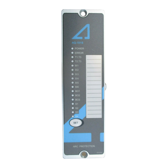
Instruction manual AQ101, AQ101D, AQ110P, AQ01 20 (48 PERATION AQ101, AQ101D, AQ110P ARC FLASH PROTECTION RELAYS 3.1.1 INDICATORS All the devices contain LED indicators for operating states as per the latter definitions. Color Steady ON Blinking Arcteq logo Blue Auxiliary supply Auxiliary power disconnected connected... - Page 21 Instruction manual AQ101, AQ101D, AQ110P, AQ01 21 (48 Color Steady ON Blinking Arcteq logo Blue Auxiliary supply Auxiliary power disconnected connected Power Blue Auxiliary supply Auxiliary power disconnected connected Error System healthy System failure Configuration mismatch. Protection partly operational. T1 / T2 / T3 / Normal status Corresponding trip relay activated...
-
Page 22: Text Pocket
Instruction manual AQ101, AQ101D, AQ110P, AQ01 22 (48 3.1.2 EXT POCKET All devices contain a text pocket for entering sensor specific information. Text pocket can be slide out and texts can be entered with a pen or with ready print paper or label. -
Page 23: Set Button
Instruction manual AQ101, AQ101D, AQ110P, AQ01 23 (48 3.1.3 ET BUTTON All devices contain a set button in the front panel, which is used for installing the system, checking the number of connected sensors and units, resetting the device after trip event and clear the alarm signals. Figure 3-2: Set button. -
Page 24: Aq01 Arc Flash Sensor
Instruction manual AQ101, AQ101D, AQ110P, AQ01 24 (48 AQ01 ARC FLASH SENSOR Figure 3-3: AQ01 sensor configuration Sensor connectors are located at both ends of the sensor for series connecting maximum three sensors in one line. After connecting the sensor to relay, the ERROR LED turns on, and the appropriate sensor channel LED starts to blink. -
Page 25: Commissioning
Instruction manual AQ101, AQ101D, AQ110P, AQ01 25 (48 OMMISSIONING AQ101, AQ101D, AQ110P ARC FLASH PROTECTION RELAYS 4.1.1 YSTEM INSTALLATION When all the connections are done, the system shall be commissioned by installing the devices one by one by pressing the set button according to the instructions on chapter 3.1.3. - Page 26 Instruction manual AQ101, AQ101D, AQ110P, AQ01 26 (48 Light channel activation Figure 4-2: Light channel activation. Light channels are commissioned by applying strong light to the light sensor detector area. The same procedure applies also for fiber sensors. Applying light to the sensor. Corresponding light sensor channel LED lights steadily when light has been detected.
-
Page 27: Activation Of Outputs (Tripping)
Instruction manual AQ101, AQ101D, AQ110P, AQ01 27 (48 4.1.3 CTIVATION OF OUTPUTS RIPPING Activation of output relays, electrical binary outputs and high-speed outputs (AQ110P only) is dependent on the application scheme of each device. Refer to chapter 2.3 for definition of scheme logics and related LED indicators in chapter Error! Reference source not found.. -
Page 28: Arc Protection Applications
Instruction manual AQ101, AQ101D, AQ110P, AQ01 28 (48 RC PROTECTION APPLICATIONS NE INCOMER Figure 5-1: One incomer application... -
Page 29: Two Incomers Without Tie Breaker
Instruction manual AQ101, AQ101D, AQ110P, AQ01 29 (48 WO INCOMERS WITHOUT TIE BREAKER Figure 5-2: two incomers without tie breaker application... -
Page 30: Two Incomers With Tie Breaker
Instruction manual AQ101, AQ101D, AQ110P, AQ01 30 (48 WO INCOMERS WITH TIE BREAKER Figure 5-3: Two incomers with tie breaker application... -
Page 31: Two Incomers With Tie Breaker
Instruction manual AQ101, AQ101D, AQ110P, AQ01 31 (48 WO INCOMERS WITH TIE BREAKER Figure 5-4: Two incomers with tie breaker application... -
Page 32: Trouble Shooting
Instruction manual AQ101, AQ101D, AQ110P, AQ01 32 (48 ROUBLE SHOOTING AQ101, AQ101D, AQ110P ARC FLASH PROTECTION RELAYS Error led IF relay Led: State state state Possible issues Binary input Blink - Bad connection between sensors or other devices or Sensor connected to BI - Damaged wire - Unit amount or sensor amount changed... -
Page 33: Technical Data
Instruction manual AQ101, AQ101D, AQ110P, AQ01 33 (48 ECHNICAL DATA AQ101, AQ101D, AQ110P ARC FLASH PROTECTION RELAYS 7.1.1 OUNTING AND INSTALLATION Panel material: Metal panel Panel thickness (min-max): 1.0 – 5 mm / 1/16” – 13/64” Panel mounting screw type: ISO 14581-M4x12 galvanized Key size: Torx T20... -
Page 34: Auxiliary Voltage
Instruction manual AQ101, AQ101D, AQ110P, AQ01 34 (48 7.1.3 UXILIARY VOLTAGE Us (min-max): 85 – 265V AC / DC Us (nominal) 110, 220 V DC, 110, 115, 220, 230 V AC 50/60 Hz 18 – 72 V DC 24, 36, 48, 60 V DC Maximum interruption in normal operating state: 100 ms Maximum power consumption:... -
Page 35: High Speed Outputs Hso1, Hso2 (Aq110P Only)
Instruction manual AQ101, AQ101D, AQ110P, AQ01 35 (48 7.1.6 HSO1, HSO2 (AQ110P PEED UTPUTS ONLY Number Rated voltage 250 V DC Continuous carry 0.5 A Make and carry for 0.5s 15 A DC Make and carry for 3s 6 A DC Make and carry for 20s 2 A DC Breaking capacity DC, when time constant... -
Page 36: Aq01 Arc Flash Sensor
Instruction manual AQ101, AQ101D, AQ110P, AQ01 36 (48 AQ01 ARC FLASH SENSOR Supply voltage 24Vdc Supply current (standby) Pick up time <1ms Sensor cable specification Shield twisted pair Size: 0.5 ~ 0.75mm2, AWG: 18 ~ 20 Cable cover: Ø 4.5 ~6.0 mm Max. -
Page 37: Dimensions
Instruction manual AQ101, AQ101D, AQ110P, AQ01 37 (48 IMENSIONS AQ101, AQ101D, AQ110P ARC FLASH PROTECTION RELAYS Figure 8-1: AQ110P device dimensions, all dimensions in millimeters. - Page 38 Instruction manual AQ101, AQ101D, AQ110P, AQ01 38 (48 Figure 8-2: AQ110P cut out for panel mounting, scaling in millimeter.
- Page 39 Instruction manual AQ101, AQ101D, AQ110P, AQ01 39 (48 Figure 8-3: AQ101 device dimensions, all dimensions in millimeters.
- Page 40 Instruction manual AQ101, AQ101D, AQ110P, AQ01 40 (48 Figure 8-4: AQ101 cut out for panel mounting, scaling in millimeter.
- Page 41 Instruction manual AQ101, AQ101D, AQ110P, AQ01 41 (48 Figure 8-5: AQ101D device dimensions, all dimensions in millimeters.
-
Page 42: Aq01 Arc Flash Sensor
Instruction manual AQ101, AQ101D, AQ110P, AQ01 42 (48 AQ01 ARC FLASH SENSOR Figure 8-6: AQ01 sensor dimensions, all dimensions in millimeters. -
Page 43: Ordering Codes
Instruction manual AQ101, AQ101D, AQ110P, AQ01 43 (48 RDERING CODES AQ101, AQ101D, AQ110P A LASH PROTECTION RELAYS... - Page 44 Instruction manual AQ101, AQ101D, AQ110P, AQ01 44 (48...
- Page 45 Instruction manual AQ101, AQ101D, AQ110P, AQ01 45 (48...
-
Page 46: Ax001 Connection Fiber
Instruction manual AQ101, AQ101D, AQ110P, AQ01 46 (48 AX001 C ONNECTION FIBER... -
Page 47: Aq01 Arc Flash Sensor
Instruction manual AQ101, AQ101D, AQ110P, AQ01 47 (48 AQ01 ARC FLASH SENSOR... -
Page 48: Reference Information
EFERENCE INFORMATION Manufacturer information: Arcteq Relays Ltd. Finland For more information regarding SIQuench® arc quenching device, please contact: Siemens Customer Support Center: Tel.: +49 180 524 70 00 Fax: +49 180 524 24 71 (Charges depending on provider) E-mail: support.energy@siemens.com...
Need help?
Do you have a question about the Arcteq AQ101 and is the answer not in the manual?
Questions and answers