
Subscribe to Our Youtube Channel
Related Manuals for ergoline ergoselect 400


Summary of Contents for ergoline ergoselect 400
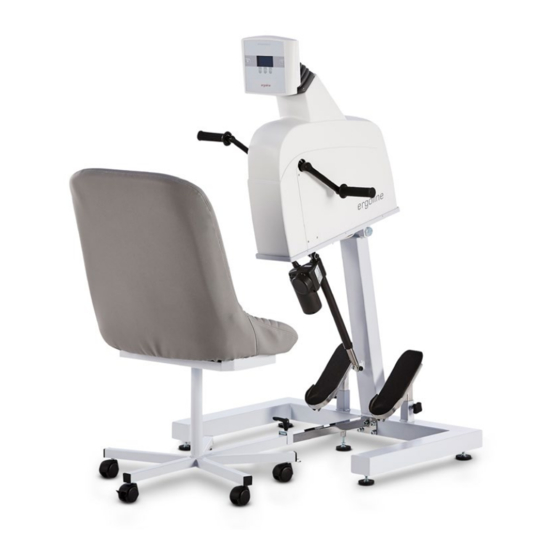
- Page 1 400 Arm Ergometer Operator’s Manual 201000160000 • Version 2020-01-14 / Rev 03 • English...
- Page 2 No part of this manual may be reprinted, translated or reproduced without the manufacturer's written permission. This manual is not subject to any change order service. Please contact the manufacturer for the latest document revision. ergoline GmbH Lindenstraße 5 72475 Bitz Germany Tel.:...
-
Page 3: Table Of Contents
ontents General Information Safety Information Intended Use Symbols Setup and Mains Connection Controls and Indicators Ergometer Setup Mounting the Special Chair Mounting the Wheelchair Access Ramp Application Connecting the Power Cord Connecting the ECG Cable Transport Preparing the Patient Operation Control terminal P Turning the System On Operating Modes with Control Terminal P... - Page 4 - 4 - - 4 -...
-
Page 5: General Information
Please note that information pertinent used. to several chapters is given only once. Therefore, read the manual once carefully in its entirety. • ERGOLINE is responsible for the safety, reliability, and performance of the equipment, only if • The symbols mean: ‑... -
Page 6: Safety Information
Explosion hazards may result from the use of flammable anest- leakage currents do not present a hazard. hetics, skin cleansing agents or disinfectants. In case of questions, please contact your ERGOLINE dealer or the ergoline GmbH Service Department. Warning For use, the ergometer must always be connected to electric •... - Page 7 afety nformatIon for ontraIndICatIons ‑I nvasIve lood ressure The following patient categories are excluded from using easurement the device: • patients feeling discomfort or suffering from dizziness, Warning nausea or pain. • Patient Hazard • • patients under the influence of substances that may impair vigilance (alcohol, drugs, medication).
-
Page 8: Intended Use
If you have questions in this matter, please contact equipment. ERGOLINE or a representative. Note – Applied Parts PPlICaBle eGulatIons and IreCtIves •... -
Page 9: Symbols
ymBols Symbol ’type B applied part’ Manufacturer’s identification Type B applied parts have no direct contact with patients and offer the lowest protection against electric shock Date of manufacture The number found under this symbol is the date of Symbol ’type BF applied part’ manufacture in the YYYY-MM-DD format Type BF applied parts are connected to the body of the patient and provide a higher degree of pro-... -
Page 10: Setup And Mains Connection
etuP and aIns onneCtIon ontrols and ndICators Control terminal (model P or model K) Handgrips Special chair Mains connection Power switch (green button) Cable connections Foot rests Strain relief for cable 400 - ergoselect controls connections and indicators Adjustable feet to compensate for uneven floor conditions 10 Fixture for special chair / wheelchair - 10 -... -
Page 11: Ergometer Setup
Now unscrew the adjustable foot of the chair's guide tube until it is flush on the floor, but make sure that the foot does not lift the ergoselect 400 base plate off the ground. Tighten the nut M10 with a fork wrench SW 17. -
Page 12: Mounting The Wheelchair Access Ramp
ountInG the heelChaIr CCess • Slide the support tubing of the wheelchair ramp onto the guide tube on the ergoselect arm ergometer (1) and tighten the clamping lever (2). ounting the wheelchair access raMp • Tighten the two nuts between support tubing and ramp (3) by hand. -
Page 13: Connecting The Power Cord
onneCtInG the ower Caution • Power input, power switch and the connections for • Equipment Damage • external devices are located on the back of the drive unit. Before connecting the ergometer to the power line, check that the line voltage corresponds to the ratings on the type plate. The type plate is located on the back of the ergometer, at the bottom. -
Page 14: Connecting The Ecg Cable
Digital connection RS232 (remote control by PC or ECG recorder, train reliefs for cables Hint • connecting cables • Only use connecting cables released by ergoline. To use the integrated USB connector, a special driver is required - contact ergoline. ransPort Caution •... -
Page 15: Preparing The Patient
reParInG the atIent Adjust the seat and the height of the load unit to positions that allow the patient to reach the handgrips easily. The height of the load unit is electrically adjustable. The motor is operated via keys on the control terminal. djusting the drive unit If the optional access ramp for wheelchairs is used, posi‑... -
Page 16: Operation
Control terminal P Control terminal K ontrol termInal urnInG the ystem ergoline You turn the ergometer on by pressing the power switch ‑ the green indicator in the switch lights up. The ergometer runs a self‑test. Subsequently, the main GmbH menu displays. -
Page 17: Operating Modes With Control Terminal P
PeratInG odes wIth ontrol ermInal An ergoselect ergometer with a control terminal P supports the following operating modes: PC MODE An external device (e.g. stand‑alone electrocardio‑ graph, PC‑based ECG system) controls the ergometer ‑ no intervention at all is required at the ergometer. ERGOMETRY The ergometer runs an automatic exercise test ‑... -
Page 18: Pc Mode
The display changes ‑ the ergometer is waiting for com‑ mands from the external ECG unit. With the arrrow keys, the saddle height can be electrically adjusted on the ergoselect 200 (on the ergoselect 400, these keys adjust the height of the drive unit). Saddle... -
Page 19: Ergometry
rGometry Use the softkeys on the right and left (↑ ↓) to position the PC Mode bar cursor on ERGOMETRY and confirm the selection with Ergometry SELECT. Manual Settings Select ain Menu Protocols The stored test protocols available for selection will be dis played. - Page 20 Note • The saddle height (ergoselect 200) can be changed during an exercise test. • To reactivate the saddle height adjustment function, press and the arrow keys will again be displayed. • Additional blood pressure measurements can be initiated with ermInatInG an xerCIse The exercise phase can be terminated manually at any time...
-
Page 21: Manual
anual Use the softkeys on the right and left (↑ ↓) to position the PC Mode bar cursor on MANUAL and confirm the selection with Ergometry SELECT. Manual Settings In this operating mode the user controls the entire exercise test by selecting the loads, stage times and by initiating blood pressure measurements. -
Page 22: Settings With Control Terminal P
ettInGs wIth ontrol ermInal Some of the device settings are configurable to meet spe‑ PC Mode cific requirements. The settings will be saved and remain Ergometry stored even when the ergometer is switched off. Manual Use the softkeys on the right and left (↑ ↓) to position the Settings bar cursor on SETTINGS and confirm the selection with SELECT. - Page 23 Protocol Use the softkeys ↑ ↓ to select the parameter to edit. Select Step At Select, for example, you can choose the protocol type: Basic Load 25 W Stage Time 2 min ‑ Step (load increase in steps) or Load Stage 25 W ‑...
- Page 24 anGuaGe Language The texts can be displayed in different languages. Deutsch English Français Español Italiano Select anguage Menu Beep The audio signal emitted during blood pressure measure‑ ments can be turned on and off. Select eep during MeasureMents oftware ersIon Select this option to view the installed software version.
- Page 25 eKG t EKG Type The selected EKG Type determines the communication method with the ECG recorder, PC‑based ECG system, etc. To prevent an accidental change of this setting, the menu is protected with a password. Using the arrow keys, enter 003 and confirm the entry with SELECT.
- Page 26 Here you determine the RPM limits. When these limits are exceeded, the LEDs for high or low speed (RPM) will Min ↑ 0 ... 70 illuminate. Select the value to change (Min. or Max.) and confirm with Max ↓ 50 ... 130 SELECT.
-
Page 27: Control Terminal K
You turn the ergometer on by pressing the power switch ‑ the green indicator in the switch lights up. The ergometer runs a self‑test. Subsequently, the main GmbH menu displays. Selftest running test screen Note •... -
Page 28: Operating Modes With Control Terminal K
PeratInG odes wIth ontrol ermInal An ergoselect ergometer with a control terminal K supports the following operating modes: PC MODE TEST An external device (e.g. stand‑alone electrocardio‑ Integrated test protocols (steep ramping test, PWC graph, PC‑based ECG system) controls the ergometer ‑ tests) allow an assessment of the physical fitness. -
Page 29: Pc Mode
↑ Saddle ↓ With the arrrow keys, the saddle height can be electrically adjusted on the ergoselect 200 (on the ergoselect 400, these key adjust the height of the drive unit). PC Mode: Waiting for start nitial screen in Mode... -
Page 30: Ergometry
rGometry The ergometer is controlled by an internally stored protocol. Pressing the "Ergometry" key will display the test protocol Ergometry WHO used last. ↑ Saddle Press the "Start" key to re‑start the protocol, or press the "Select" key to display the protocol parameters or to switch ↓... - Page 31 djustments urInG the xerCIse Press the key to display the configuration menu. This is what you can do during the test • increase or decrease the current load in increments Load + Recovery phase (adjustable between 1 watt and 25 watts) •...
-
Page 32: Manual
anual In this operating mode the user controls the entire exercise test by selecting the loads, stage times and by initiating blood pressure measurements. Load + Saddle ↑ The exercise test is started with the "Start" key, afterwards the load can be set and changed with the [Load +] and Load - Saddle ↓... -
Page 33: Training
raInInG Cardiologic training sessions can be performed with ergo‑ select ergometers equipped with control terminal K. For a detailed description of the protocols, please refer to Training No.1 Pulse the Appendix. ↑ Saddle Pressing the "Training" key will display the training protocol used last. -
Page 34: Training With Chip Card
The training protocols are saved to the chip card by means of a PC program ("ergoline opticare professional" or "ergo‑ line opticare basic"). Upon completion of the training session, the entire proce‑... - Page 35 Training Chipcard The name and the weight stored on the card are displayed. Sumner You can use the arrow keys to enter the current weight. David Weight + 93 kg Press the "Next" key and the initial screen will display. Weight - You can initiate the displayed training protocol or select another protocol from the chip card.
-
Page 36: Settings For Control Terminals K
ettInGs for ontrol ermInals Some of the device settings are configurable to meet spe‑ cific requirements. The settings will be saved and remain stored even when the ergometer is switched off. Settings Select SETTINGS to display the configuration menu. Default Mode When all changes have been made, you can exit the confi‑... - Page 37 Use the softkeys ↑ ↓ to select the parameter to edit. Protocol Select Step At Select, for example, you can choose the protocol type: Basic Load 25 Watt ↑ Stage Time ‑ Step (load increase in steps) or ‑ Ramp (continuous load increase). Load Stage 25 Watt NIBP Lead Time 60...
- Page 38 hanGe Here you determine the increments for each load change. Load Change Depending on your choice, each key press will change the load by +/‑ 1, 5, 10 und 25 watts. 1 Watt ↑ 5 Watt 10 Watt 25 Watt ↓...
- Page 39 Date/Time To begin with, you select DATE or TIME and confirm the selection. Then the value displayed in reverse video can be edited Date with the ↑ ↓ keys and saved with SELECT. ↑ 14. 01. 2020 Time The time is set in the same way. You exit the configuration with 17 : 33: 51 ↓...
- Page 40 Training For all training modes (pulse, constant load and interval), the warmup phase, the duration of the training session Select Pulse and the recovery phase are defined first. Basic Load Watt Depending on the selected training mode, you can edit the ↑...
- Page 41 eKG t The selected EKG Type determines the communication EKG Type method with the ECG recorder, PC‑based ECG system, etc. To prevent an accidental change of this setting, the menu ↑ is protected with a password. Using the arrow keys, enter 003 and confirm the entry with SELECT.
- Page 42 Here you determine the RPM limits. When these limits are exceeded, the LEDs for high or low speed (RPM) will illuminate. Min ↑ 0 ... 70 ↑ Select the value to change (Min. or Max.) and confirm with SELECT. Max ↓ 50 ...
-
Page 43: Cleaning, Maintenance, Disposal
leanInG aIntenanCe IsPosal eneral leanInG Warning • Shock Hazard • Wipe the device surface down with a cloth moistened with soap water or a disinfectant. The cloth should not be dripping wet; do not allow liquids • Disconnect the device from the power line before cleaning. to enter the device. - Page 44 leanInG the lood ressure emovInG the ICroPhone Pull the end of the cuff through the metal clasp and fold out the cuff. Pull on the short Velcro tab to open the microphone pock‑ et and carefully remove the microphone. leanInG Clean the cuff and tubing with a moist cloth.
- Page 45 Do not dispose the product described in this Operator Manual as unsorted municipal waste. It must be collected separately. Please contact the authorized manufacturer ergoline GmbH to obtain information concerning the decommissioning of your equipment. There is no proper waste management, proper disposal is documented by ergoline GmbH.
-
Page 46: Technical Specifications
PeCIfICatIons rGometer Model modular ergometer system ergoselect models ergoselect 400 P / K Operating Mode continuous operation Power 100 ‑ 240 V / 50 ‑ 60 Hz (100 VA max.) specification power cord US: SPT 2x18AWG 125 V / 10 A “hospital“... - Page 47 Dimensions, Weight length: 130 cm width: 87 cm height: 135 cm weight: approx. 73 kg Safety Standards DIN EN 60601‑1, DIN EN 60601‑1‑2, DIN VDE 0750‑238 Protection Class / Degree of Protection / B (arm ergometer) BF (blood pressure module) MDD Classification class IIa to 93/42 EEC RF Emission...
- Page 48 xerCIse rotoCols Protocol initial load time in stage load recovery load recovery time [min] increment [min] 1. WHO 2. BAL 3. Hollmann 4. STD France 5. Standard 6. ‑ 15. (user‑programmable) Adjustment Range 20 ‑ 100 1 ‑ 30 1 ‑ 400 20 ‑...
- Page 49 amIly of CharaCterIstICs of the BraKInG torque Control ranGe black: speed‑independent range to DIN VDE 0750‑0238 black + grey: speed‑independent range of the ergoselect ergometer IeC 60601‑1 amIly of CharaCterIstICs of the load PerIods aCCordInG to Under permanent load, the load periods and pauses (white) shall be observed. - 49 -...
-
Page 50: Electromagnetic Compatibility En 60601-1-2
60601‑1‑2 Warning Changes or modifications to this system not expressly • RF INTERFERENCE • approved by ergoline could cause EMC issues with this or other equipment. • Use of portable telephones or other radio frequency (RF) This system is designed to comply with applicable regula‑... - Page 51 ’ – e uIdanCe and anufaCturer eClaratIon leCtromaGnetIC mmunIty The ergoselect ergometer is intended for use in the electromagnetic environment specified below. It is the responsibility of the customer or user to ensure that the ergoselect ergometer is used in such an environment. Immunity Test IEC 60601 Test Level Compliance Level Electromagnetic Environment - Guidance...
- Page 52 ’ – e uIdanCe and anufaCturer eClaratIon leCtromaGnetIC mmunIty The ergoselect ergometer is intended for use in the electromagnetic environment specified below. It is the responsibility of the customer or user to ensure that the ergoselect ergometer is used in such an environment. Immunity Test IEC 60601 Test Level Compliance Level Electromagnetic Environment - Guidance...
- Page 53 eCommended seParatIon dIstanCes Between PortaBle and moBIle CommunICatIons equIPment and the erGoseleCt erGometer The ergoselect ergometer is intended for use in the electromagnetic environment in which radiated RF disturbances are controlled. The customer or the user of the ergoselect ergometer can help prevent electromagnetic interference by maintaining a minimum distance between portable and mobile RF communications equipment (transmitters) and the ergoselect ergometer as recommended below, according to the maximum output power of the communications equipment.
- Page 54 - 54 -...
- Page 56 GmbH Lindenstraße 5 72475 Bitz Germany Tel.: +49-(0) 7431 98 94 - 0 Fax: +49-(0) 7431 98 94 - 128 e-mail: info@ergoline.com http: www.ergoline.com...
Need help?
Do you have a question about the ergoselect 400 and is the answer not in the manual?
Questions and answers