ergoline ergoselect 10 M Operator's Manual
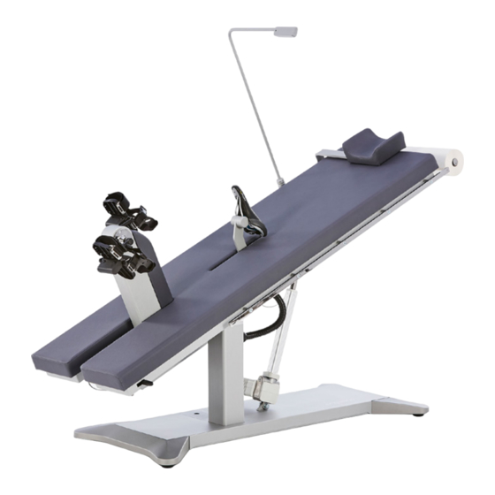
Couch ergometer
Hide thumbs
Also See for ergoselect 10 M:
- Manual (18 pages) ,
- Operator's manual (96 pages) ,
- Operator's manual (66 pages)

Related Manuals for ergoline ergoselect 10 M


Summary of Contents for ergoline ergoselect 10 M
- Page 1 ergoselect 10 Couch Ergometer Operator's Manual 201000546000 • Version 2018-10-08 / Rev 01 • English...
- Page 3 This manual will not be automatically updated. Please contact the manufacturer for the latest document revision. This manual also describes optional components that are not included in the standard scope of delivery of this product. ergoline GmbH Lindenstrasse 5 72475 Bitz Germany Tel.:...
- Page 4 ergoselect 10...
-
Page 5: Table Of Contents
Contents Contents General Information Safety Information 2 1 Safety Information for Non‑Invasive Blood Pressure Measurement 2 2 Contraindications 2 3 Intended Use 2 4 Biocompatibility 2 5 Applicable Laws, Regulations and Directives Symbols Setup and Mains Connection 4 1 Controls and Indicators 4 2 Transport 4 3 Setup 4 4 Mounting Attachment Parts... - Page 6 Cleaning, Maintenance, Disposal 9 1 General Cleaning 9 2 Cleaning the Saddle 9 3 Disinfection 9 4 Cleaning the Blood Pressure Cuff 9 4 1 Removing the Microphone 9 4 2 Cleaning 9 4 3 Disinfection 9 4 4 Inserting the Microphone 9 5 Maintenance 9 5 1 Checks Before Each Use 9 5 2 Technical Safety Inspections and Inspections of the Measuring System 49...
-
Page 7: General Information
1 General Information 1 General Information • The product ergoselect bears the CE marking CE‑0123 • On request ergoline GmbH will provide a Field Service (Notified Body: TÜV), indicating its compliance with the Manual. provisions of the Council Directive 93/42/EEC about medical devices and fulfills the essential requirements •... -
Page 8: Safety Information
Attention is drawn to the fact that local laws take priority over the above mentioned requirements. Note If in doubt, please consult your local dealer or ergoline GmbH. The device characteristics determined by emissions allow the device to be used in industrial environments and in hospitals (CISPR 11, class A). -
Page 9: 1 Safety Information For Non-Invasive Blood Pressure Measurement
• If the cuff pressure remains constant for some time, the ments of the applicable standards if applied as intended. measurement will also be aborted and the cuff deflated. If you have questions in this matter, please contact ergoline GmbH or an ergoline GmbH representative. ergoselect 10... -
Page 10: 5 Applicable Laws, Regulations And Directives
2 Safety Information 2.5 Applicable Laws, Regulations and Directives If you have questions about the validity of applicable laws, regulations and directives, please contact ergoline GmbH. ergoselect 10... -
Page 11: Symbols
3 Symbols 3 Symbols Symbol 'type B applied part' Manufacturer’s identification Type B applied parts have no direct contact with patients and offer the lowest protection against electric shock Date of manufacture The number found under this symbol is the date of Symbol 'type BF applied part' manufacture in the YYYY‑MM‑DD format Type BF applied parts are connected to the body of... -
Page 12: Setup And Mains Connection
4 Setup and Mains Connection 4 Setup and Mains Connection 4.1 Controls and Indicators 1 Speed readout for the patient 2 Arm rest for blood pressure measurements (right or left, only on devices with automatic blood pressure measurement) 3 Connections for blood pressure cuff (below the couch surface) 4 Release lever for ergometry unit 5 Connections for power cord and connection cables... -
Page 13: 3 Setup
4 Setup and Mains Connection 4.3 Setup Several persons should be present to set up the ergoselect 10. Caution • Patient Hazard / Equipment Damage • The ergoselect 10 must be set up on a horizontal level floor. During assembly, the ergometer must be disconnected from the power line. - Page 14 4 Setup and Mains Connection • Mount the holder for the exam table paper roll by means of two countersunk screws M6x20 which are screwed into the frame. Figure 4 – 6: Mounting the holder for the exam table paper roll Caution •...
-
Page 15: 5 Connecting The Power Cord
4 Setup and Mains Connection • Introduce the saddle post into the saddle guide rail and press down lightly until the post locks into place. Figure 4 – 9: Introducing the saddle post into the guide rail Caution • Equipment Damage • If your ergometer has a separate control terminal, be sure to route the connection cable to the control terminal out of the way to prevent any stumbling hazard. -
Page 16: 6 Connecting The Ecg Cable
All ergoselect ergometers are equipped with a digital interface. (Special adapters are needed for analog control or the remote start capability. Please contact ergoline GmbH for these adapters.) Figure 4 – 11: Connection for ECG recorder / PC ECG system... - Page 17 4 Setup and Mains Connection Concerning its functionality, the control terminal on the underside of the Couch Ergometer is equivalent to control terminal M (see section 8.1 Control Terminal M on page 20). For putting the unit into service, remove the control termi‑ nal from below the couch surface.
-
Page 18: Operation
5 Operation 5 Operation 5.1 Adjusting the Couch The saddle and the couch position are adjusted with the remote control (see Figure 5 – 1): Keys 1: saddle adjustment Keys 2: incline adjustment (0 to 45°) The yellow indicator is illuminated while any of the adjustment keys is pressed. -
Page 19: Preparing The Patient
6 Preparing the Patient 6 Preparing the Patient 6.1 Preparing the Couch with the Patient Before the patient can lie down on the couch, the ergometer must be prepared as follows: • Lower the saddle to the bottom position. • Remove the saddle. •... -
Page 20: Preparing The Patient For Blood Pressure Measurements
7 Preparing the Patient for Blood Pressure Measurements 7 Preparing the Patient for Blood Pressure Measurements 7.1 Cuff Size Always choose the cuff size suitable for the patient's arm. The maximum arm circumference is indicated on the cuff. Figure 7 – 1: Correct cuff size Figure 7 –... -
Page 21: 3 Applying The Cuff
7 Preparing the Patient for Blood Pressure Measurements 7.3 Applying the Cuff The center of the microphone must be located exactly on the brachial artery. Locate the artery by palpation if required. The red tab identifies the position of the microphone. The accurate placement of the microphone is the primary condition for reliable pressure measurement during exer‑... -
Page 22: Control Terminals
8 Control Terminals 8 Control Terminals 8.1 Control Terminal D / M Figure 8 – 1: Control terminal D (Service) Figure 8 – 2: Control terminal M (remote control) (installed under the couch surface – standard) (separate terminal – option) The two terminals are identical in operating routines and functionality. -
Page 23: 1 2 Operating Mode With Control Terminal M
8 Control Terminals 8.1.2 Operating Mode with Control Terminal D / M Ergometers with control terminal D / M support the following operating mode: PC Mode An external device (e.g., an ECG recorder, a PC-based ECG system) controls the ergometer – no intervention at all is required at the Couch Ergometer. -
Page 24: 2 Control Terminal P
8 Control Terminals 8.2 Control Terminal P 8.2.1 Turning the System On You turn on the ergometer by pressing the power switch (toggle switch [ I / 0 ] ). The ergometer runs a self‑test. Subsequently, the main menu displays. Figure 8 – 7: Control terminal P Note •... -
Page 25: 2 2 Operating Modes
8 Control Terminals 8.2.2 Operating Modes Ergometers with control terminal P support the following operating modes: PC Mode An external device (e.g., an ECG recorder, a PC‑based ECG system) controls the ergometer – no intervention at all is required at the ergometer. Ergometry The ergometer runs an automatic exercise test –... - Page 26 8 Control Terminals As soon as the ergometer receives commands from the controlling ECG unit or PC, the exercise test will start and the corresponding values will be displayed. The exercise test can only be terminated with the corre‑ sponding command from the controlling ECG unit. Figure 8 –...
- Page 27 8 Control Terminals The stored test protocols available for selection will be dis‑ played. There are five fixed protocols (protocols 1 to 5, (see section 10.3 Exercise Test Protocols on page 52)), whereas protocols 6 to 15 are user‑programmable. The protocol menu provides an overview of the test phases. Example: 50 W / 2 min / 25 W indicates: Basic load of 50 W Stage time of 2 min...
- Page 28 8 Control Terminals Terminating an Exercise Test The exercise phase can be terminated manually at any time with the Recovery key. The load will immediately be reduced to 25 watts, but a higher or lower value can be selected manually. It is recommended that the patient continue to pedal in the recovery phase.
- Page 29 8 Control Terminals 8.2.2.4 Settings with Control Terminal P Some of the device settings are configurable to meet spe‑ cific requirements. The settings will be saved and remain stored even when the ergometer is switched off. Use the softkeys on the right and left (↑ ↓) to position the bar cursor on Settings and confirm the selection with Select.
- Page 30 8 Control Terminals Use the right and left softkeys (↑ ↓) to select the parameter to edit. At Select, for example, you can choose the protocol type: — Step (load increase in steps) or — Ramp (continuous load increase). Press Select to save the selected protocol type. To cancel the selection, press the Figure 8 –...
- Page 31 8 Control Terminals Language The texts can be displayed in different languages. Figure 8 – 30: Language menu Beep The audio signal emitted during blood pressure measure‑ ments can be turned on and off. Figure 8 – 31: Beep during BP measurements Software Version Select this option to view the installed software version.
- Page 32 8 Control Terminals EKG Type The selected EKG Type determines the communication method with the ECG recorder, PC‑based ECG system, etc. To prevent an accidental change of this setting, the menu is protected with a password. Using the arrow keys, enter 003 and confirm the entry with Select.
- Page 33 8 Control Terminals Here you determine the RPM limits. When these limits are exceeded, the LEDs for high or low speed (RPM) will illuminate. Select the value to change (Min. or Max.) and confirm with Select. Using the arrow keys, change the value and save the new value with Select.
-
Page 34: 3 Control Terminal T
8 Control Terminals 8.3 Control Terminal T 8.3.1 Turning the System On You turn on the Couch Ergometer by pressing the power switch (toggle switch[ I / 0 ]). Note • Instruct the patient not to pedal while the ergometer is being turned on and during the selftest. •... -
Page 35: 3 2 Operating Modes With Control Terminal T
8 Control Terminals 8.3.2 Operating Modes with Control Terminal T Couch Ergometers with control terminal T support the following operating modes: PC Mode An external device (e.g., an ECG recorder, a PC‑based ECG system) controls the ergometer – no intervention at all is required at the Couch Ergometer. - Page 36 8 Control Terminals 8.3.2.1 PC Mode When the [ PC Mode ] key has been pressed, the screen appears as shown at right. The Couch Ergometer is waiting for commands from the external ECG unit. As soon as the ergometer receives commands from the controlling ECG unit or PC, the exercise test will start and the corresponding values will be displayed.
- Page 37 8 Control Terminals 8.3.2.2 Ergometry Pressing the [ Ergometry ] key in the main menu activates the ergometry mode. The different exercise test protocols will be displayed (5 preconfigured, editable and 5 user‑configurable proto‑ cols). All exercise test protocols (including the 5 preconfigured protocols) are editable. Figure 8 –...
- Page 38 8 Control Terminals With the [ 2. ] key, you proceed to the next menu level where you can edit these parameters: • the recovery load (from 6 to 100 W) and • the recovery time (from 1 to 30 min). With the [ 1. ] key, you return to the previous screen. Figure 8 –...
- Page 39 8 Control Terminals Terminating the Program Once the full protocol has been completed, it terminates automatically. The program can be terminated manually before the end of the protocol with [ Stop ]. First, you enter the recovery phase. When you touch [ Stop ] again, the training will be termi‑ nated.
- Page 40 8 Control Terminals Then press the [ Edit ] key. Figure 8 – 57: Editing the Training / Test protocol The individual parameters (light gray fields) can now be edited by touching the display or by repeatedly tapping [ ]. If you need to input characters (numbers or letters), an (alpha‑) numeric keypad or a keyboard will be displayed.
- Page 41 8 Control Terminals 8.3.2.4 Manual In this operating mode the user has complete control over the Couch Ergometer and initiates blood pressure measure‑ ments. Pressing the [ Start ] key initiates the exercise test, the [ + 5 W ] and [ – 5 W ] keys are used to control the load. The actual load change can be set in the configuration menu between +/–...
- Page 42 8 Control Terminals Default Mode Select the operating mode to be activated when the couch ergometer is turned on: • PC Mode • Ergometry • Training / Test • Manual and confirm the selection with the [ ] key. Figure 8 – 63: Default mode setup Protocols The first 5 exercise test protocols (WHO, BAL, Hollm, Std Fr and Standard) are preconfigured, but all protocols in the...
- Page 43 8 Control Terminals At Type, you can choose [ Step ], [ Ramp ] or [ Inactive ]. You scroll through the Type options with the [ ] key. When choosing the Step type (load increase in steps), define the basic load (from 6 to 100 W), the stage time (from 1 to 30 min) and the stage rate (increment, from 1 to 400 W).
- Page 44 8 Control Terminals The following communication modes are supported: • Analog with pulse Remote start mode; before advancing to the next load level, the Couch Ergometer generates a control pulse and sends the corresponding data via the interface. • Analog / Digital An analog voltage controls the load –...
- Page 45 8 Control Terminals Date/Time Touch the respective fields to adjust date and time. Enter day, month, year as well as hours, minutes and seconds via the numeric keypad. Inputs are confirmed with the [ ] key. Figure 8 – 72: Setup – date and time, screen 1 Figure 8 –...
- Page 46 8 Control Terminals In this menu, you determine the limits for the RPM indica‑ tion. The 3 LEDs on the control panel show the patient whether the pedal speed is high, low or correct. Figure 8 – 76: Setup – RPM, screen 1 Touch the light gray field to the right of Min.
- Page 47 8 Control Terminals Software Version This menu shows the software version and the date of the technical inspection of the measuring system (MTK). Figure 8 – 79: Setup – software version Language Here you choose the language for the user interface. Figure 8 –...
- Page 48 8 Control Terminals Switch the pulse readout on or off. Select the blood pressure unit: mmHg (millimeter of mer‑ cury) or kPa (kilopascal). Figure 8 – 82: Setup – screen display 2 ergoselect 10...
-
Page 49: Cleaning, Maintenance, Disposal
9 Cleaning, Maintenance, Disposal 9 Cleaning, Maintenance, Disposal 9.1 General Cleaning Wipe the device surface down with a cloth moistened with Warning soap water or a disinfectant. • Shock Hazard • • Disconnect the device from the power line before cleaning. The cloth should not be dripping wet;... -
Page 50: 4 Cleaning The Blood Pressure Cuff
9 Cleaning, Maintenance, Disposal 9.4 Cleaning the Blood Pressure Cuff 9.4.1 Removing the Microphone Pull the end of the cuff through the metal clasp and fold out the cuff. Pull on the short Velcro tab to open the microphone pocket and carefully remove the microphone. -
Page 51: 4 4 Inserting The Microphone
The product described in this operator manual must not be disposed as unsorted municipal waste; it must be collected separately. Please contact your authorized manufacturer ergoline GmbH for information concerning the disposal of your equipment. There is no waste disposal certificate. Proper disposal is documented by ergoline GmbH. -
Page 52: Technical Specifications
10 Technical Specifications 10 Technical Specifications 10.1 Ergometer Model modular couch ergometer system ergoselect Model ergoselect 10 M / P / T Operating mode continuous operation Power 90 – 264 V / 47 – 63 Hz / 200 VA max. -
Page 53: 10 2 Blood Pressure Module
10 Technical Specifications Safety standards DIN EN 60601‑1, DIN EN 60601‑1‑2, DIN VDE 0750‑238 Protection class / degree of protection I / B (couch ergometer) BF (blood pressure module) MDD classification class IIa to 93/42 EEC RF emission class A to DIN EN 55011 (VDE 0875‑11) / 04/2011, DIN EN 60601‑1‑2 Environment operation:... -
Page 54: 10 3 Exercise Test Protocols
10 Technical Specifications 10.3 Exercise Test Protocols Protocol Basic Load Stage Time Load Stage Recovery Load Recovery Time [min] [min] 1. WHO 2. BAL 3. Hollmann 4. STD France 5. Standard 6. – 15. (user programmable) Adjustment Range 20 – 100 1 –... -
Page 55: 10 5 Family Of Characteristics Of The Braking Torque Control Range
10 Technical Specifications 10.5 Family of characteristics of the braking torque control range 25 100 1000 Watt Load Figure 10 – 1: black: speedindependent range to DIN VDE 07500238 black + gray: speedindependent range of the ergoselect ergometer 10.6 Family of characteristics of the load periods according to IEC 60601‑1 Figure 10 –... - Page 56 11 Electromagnetic Compatibility EN 60601‑1‑2 11 Electromagnetic Compatibility EN 60601‑1‑2 Changes or modifications to this system not expressly approved by ergoline GmbH could cause EMC issues with Warning this or other equipment. • RF Interference • Use of portable phones or other radio frequency (RF) emitting This system is designed to comply with applicable regula‑...
- Page 57 11 Electromagnetic Compatibility EN 60601‑1‑2 Guidance and Manufacturer’s Declaration – Electromagnetic Immunity The ergoselect ergometer is intended for use in the electromagnetic environment specified below. It is the responsibility of the customer or user to ensure that the ergoselect ergometer is used in such an environment. Immunity Test IEC 60601 Test Level Compliance Level Electromagnetic Environment –...
- Page 58 11 Electromagnetic Compatibility EN 60601‑1‑2 Guidance and Manufacturer’s Declaration – Electromagnetic Immunity The ergoselect ergometer is intended for use in the electromagnetic environment specified below. It is the responsibility of the customer or user to ensure that the ergoselect ergometer is used in such an environment. Immunity Test IEC 60601 Test Level Compliance Level Electromagnetic Environment –...
- Page 59 11 Electromagnetic Compatibility EN 60601‑1‑2 Recommended separation distances between portable and mobile RF communications equipment and the ergoselect ergometer The ergoselect ergometer is intended for use in an electromagnetic environment, as specified below, in which radiated RF disturbances are controlled. The customer or the user of the ergoselect ergometer can help prevent electromagnetic inter‑ ference by maintaining a minimum distance between portable and mobile RF communications equipment (transmitters) and the ergoselect ergometer as recommended below, according to the maximum output power of the communications equipment.
- Page 60 11 Electromagnetic Compatibility EN 60601‑1‑2 201000546000 • Version 2018‑10‑08 / Rev 01 • English ergoselect 10...
- Page 62 GmbH Lindenstraße 5 72475 Bitz Germany Tel.: +49-(0) 7431 98 94 - 0 Fax: +49-(0) 7431 98 94 - 128 e-mail: info@ergoline.com http: www.ergoline.com...
Need help?
Do you have a question about the ergoselect 10 M and is the answer not in the manual?
Questions and answers