Axon Fleet 2 Installation Manual
Hide thumbs
Also See for Fleet 2:
- User manual (22 pages) ,
- Quick start manual (2 pages) ,
- Quick start manual (2 pages)
Table of Contents
Advertisement
Advertisement
Table of Contents

Related Manuals for Axon Fleet 2


Summary of Contents for Axon Fleet 2
- Page 1 Axon Fleet 2 Installation Manual Document Revision: MMU0072 Rev D February 2020...
- Page 2 Axon, Axon, Axon Evidence, Axon Fleet, Axon Signal, and Axon View XL are trademarks of Axon Enterprise, Inc., some of which are registered in the US and other countries. For more information, visit www.axon.com/legal. All rights reserved. ©2020 Axon Enterprise, Inc.
-
Page 3: Table Of Contents
Wiring Harness Assemblies ......................11 Additional Items ............................12 Installation ..............................13 Upgrading from Axon Fleet to Axon Fleet 2 ..................13 Installation Warnings and Prerequisites ....................14 General Warnings ..........................14 Vehicle Power, Ground and Ignition Inputs ................. 14 Pre-deployment Checks .......................... - Page 4 Wiring the Axon Fleet Power Unit ......................26 Axon Fleet Power Unit to Car ......................26 Axon Fleet Power Unit to Camera/Controller Mount ..............27 Affix the Front Camera Mount ....................... 28 Affix the Rear Camera Controller and Camera ..................29 Affixing the Power Unit ...........................
-
Page 5: Introduction
LTE or Wi-Fi technology to the Evidence.com website. The Axon Fleet 2 system consists of the Axon Fleet cameras, the Axon Fleet camera mounts, the Axon Fleet rear camera controller, and the Axon Fleet power unit. The Axon Fleet power unit is an inline power supply for the cameras. -
Page 6: Axon Fleet 2 Network Overview Diagram
Axon equipment. For example, the Axon Signal Vehicle unit can be set up to work with an emergency vehicle’s light bar. When the light bar activates, all properly equipped Axon systems within range can begin recording. -
Page 7: Additional Reading
Axon Fleet 2 Installation Manual Additional Reading This manual explains how to install the Axon Fleet 2 camera hardware. Other manuals cover additional aspects of the Axon Fleet 2 system. These documents are available from the Support section at www.axon.com. -
Page 8: Installation Time Estimates
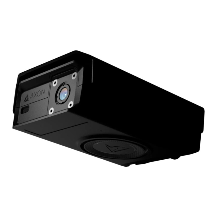
5 Min Total Installation Time with Router 130 Min Axon Fleet 2 Contents Every Axon Fleet 2 system comes with the following parts required for installation. One Axon Fleet 2 front camera – SKU 71079 Front view Back view Bottom view Axon Enterprise, Inc. - Page 9 Axon Fleet 2 Installation Manual One Front Camera Mount – SKU 71080 Axon Fleet 2 rear camera – SKU 71081 Axon Fleet 2 rear camera controller and mount – SKU 71082/71083 Axon Enterprise, Inc. Page 9 of 39...
- Page 10 This dongle is plugged in to a USB port on the vehicle's mobile data terminal (MDT), the in- vehicle Windows laptop computer. The dongle is provided by Axon and enables the MDT to have Bluetooth low-energy (BLE) capabilities. This is required for the MDT to communicate with the Axon Fleet 2 cameras.
-
Page 11: Wiring Harness Assemblies
Axon Fleet 2 Installation Manual Wiring Harness Assemblies Two power unit to camera/controller cables SKU 71085 These cables are 18 feet (5.5 m) in length. One end of the cable has a plug-in connector for the front camera or rear camera controller mount and the other has the following wires: 18 AWG –... -
Page 12: Additional Items
Installation Manual Additional Items In addition to the standard Axon Fleet 2 hardware, the agency will need to have a laptop computer, with the Axon View XL application installed. Also, a wireless router is required. Axon Fleet 2 includes a Cradlepoint IBR900 series router, unless deviations are approved by an Axon Sales Engineer. -
Page 13: Installation
Upgrading from Axon Fleet to Axon Fleet 2 If you are performing an Axon Fleet 2 installation as upgrade to an existing Axon Fleet system, it is not necessary to remove the existing power units or signal unit. The scope of installation is limited to the cameras. -
Page 14: Installation Warnings And Prerequisites
Do not install Axon Fleet 2 components or the Axon Signal Vehicle unit anywhere • that will interfere with airbag deployment. Do not install any part of the Axon Fleet 2 system or the Axon Signal Vehicle unit in • the vehicle's engine compartment. -
Page 15: Pre-Deployment Checks
Ignition Timer/Charge Guard Guidance: If you are using an ignition timer or charge guard, Axon still recommends connecting the Fleet Power Units to a constant voltage source, such as the car battery. If the constant voltage source is the ignition timer, when it times out the Fleet Power Units will stop communicating with cameras and cameras will shut down after 15 seconds. -
Page 16: Installing The Sim Card In The Cradlepoint Router
Axon Fleet 2 Installation Manual Source of GPS for the Axon View XL. If the MDT modem is the preferred source, then • the MDT must have the capability to forward GPS information to Axon View XL. Note that any software required to forward the MDT’s GPS information is not provided by Axon. -
Page 17: Inserting The Sim Card Into The Integrated Modem (Ibr900)
SIM card for every router to be associated with an IMEI. You may also need to re- provision the sim card through your carrier. The Axon Router requires a 2FF “Mini-SIM” to operate properly and agencies must have the 2FF Mini-SIM cards available prior to confirming Axon onsite installation. -
Page 18: Inserting The Sim Card Into The Integrated Modem: (Ibr1700)
Axon Fleet 2 Installation Manual 2. Insert the SIM card into sim card slot 1 with the metal contacts down and as shown below. 3. Push sim until you feel a click and the sim stays in place. Inserting the SIM Card into the Integrated Modem: (IBR1700) 1. -
Page 19: Inserting The Sim Card Into The Add-On Modem
Routers are managed through NetCloud Manager • Manage routers using Group Configurations • Configurations are pushed from NetCloud Manager to the router(s) • See the Cradlepoint Netcloud Configuration Guide for Axon Fleet for additional information • Axon Enterprise, Inc. Page 19 of 39... -
Page 20: Tools
Axon Fleet 2 Installation Manual Tools The following is a list of required and recommended tools to install the Axon Fleet 2 camera system. Required Tools • Multi-meter to test for voltage • Cable ties • #1 Phillips screwdriver • 3M Electrical tape •... -
Page 21: Axon Fleet Hardware Installation Diagrams
Axon Fleet 2 Installation Manual Axon Fleet Hardware Installation Diagrams Without Wireless Microphone Axon Enterprise, Inc. Page 21 of 39... -
Page 22: Determine The Mounting Locations
Axon Fleet Power Unit and Axon Signal Vehicle Unit Axon Fleet 2 is installed in typically three different locations. It is important to note the location of the power units, for future reference, in the event the agency needs to locate equipment. -
Page 23: Axon Fleet Power Unit
Front Camera and Mount With the Axon Fleet 2 front camera properly secured to the Axon Fleet 2 mount and without permanently affixing the mount, determine the appropriate location to affix the mount upon the interior of the windshield. -
Page 24: Locate The Vehicle's Electronics
Locate the Vehicle’s Electronics The next step to installing the Axon Fleet 2 system is locating the wiring for the vehicle. The vehicle make and model will dictate where wiring is found. The installer needs to locate the following wires: •... -
Page 25: Running The Wiring Harness
• possible between the Fleet 2 cables and the radio cables. If it is necessary to cross the two, do so at right angles and avoid running parallel lengths of Fleet 2 and radio cables. Use a shielded Fleet Power Unit to Camera cable (SKU 71085) with two ferrite clamps (RF filters) between the Fleet Power Unit and camera or junction box. -
Page 26: Wiring The Axon Fleet Power Unit
DO NOT place the clamps on the camera’s cable. The clamps must only be placed the Fleet Power Unit to Camera cable (SKU 71085). If your radios operate in the 150 – 160 MHz bands, axon recommends running the •... -
Page 27: Axon Fleet Power Unit To Camera/Controller Mount
Axon Fleet 2 Installation Manual 4. On the Axon Fleet power unit end, remove the male end of the connector. 5. Unscrew the small set screws. 6. Strip no more than 0.25″ (6.35 mm) of insulation from each of the wires. -
Page 28: Affix The Front Camera Mount
Axon Fleet 2 Installation Manual White – 12 • Violet – 9 • Green – 8 • Gray – 7 • 4. Tighten down the set screws. 5. Reconnect the male connector to the power unit. 6. Secure the male connector using the small set screws on either end of the connector. -
Page 29: Affix The Rear Camera Controller And Camera
The cable is approximately 4 feet long. For the rear camera, the installer can use Axon View XL to find the location that best views the cage area. After the camera is mounted, the installer can use the angle adjustment screws to adjust the vertical view of the camera. -
Page 30: Affixing The Power Unit
Axon Fleet 2 Installation Manual 3. Peel the top protective layer from the adhesive strip and affix the mount to the area. 4. Hold the mount in place for 10 seconds to ensure adhesion. 5. Connect the power unit to controller mount cable to the mount. -
Page 31: Axon Signal Vehicle Unit
When that hardware is used, Axon Signal Vehicle transmits a message recognizable by Axon Signal compatible equipment. For example, Axon Signal Vehicle can be set up to work with an emergency vehicle’s light bar. When the vehicle light bar is activated, all properly equipped Axon systems within range begin recording. -
Page 32: Axon Signal Vehicle Wiring Instructions
Note: Power ground and Ignition are found from the power unit to vehicle cable (SKU 71100) Optional Auxiliary Enable (position 4) The J2-4 input is used to provide an alternate signal to Axon Signal Vehicle for enabling the system. Note: Either the Ignition Enable or Auxiliary Enable input on Axon Signal Vehicle must be used for the device to turn on. -
Page 33: Optional Door Trigger Installation
VDC present while the trigger is enabled. 3. Turn the trigger off and verify that the voltage drops to zero. For Axon Signal Vehicle to work optimally, the trigger should provide a constant voltage to the device when it is activated. -
Page 34: Axon Fleet 2 Wireless Microphone Contents
If your agency is not installing wireless microphones with your Axon Fleet 2 system, skip this section. Axon Fleet 2 Wireless Microphone Contents Every Axon Fleet 2 Wireless Microphone system comes with the following parts required for installation. One Axon Fleet 2 wireless microphone – SKU 71086 One junction box –... - Page 35 Axon Fleet 2 Installation Manual One in-car charging dock and one charging dock to vehicle cable – SKU 71087 One lapel microphone accessory – SKU 71102 One socket plug – SKU 71103 Axon Enterprise, Inc. Page 35 of 39...
-
Page 36: Additional Tools
Axon Dock with bays for Axon Body 2 cameras, for in station charging of the wireless • microphones Additional Tools The following is a list of required and recommended tools to install the Axon Fleet 2 wireless microphone junction box and in-car charging dock. Alcohol wipes and paper towels •... -
Page 37: Affix The Junction Box
4. Connect the junction box to the Axon Fleet power unit and to the front camera. Connecting the Junction Box The junction box connects in series between the Axon Fleet Power Unit and the Axon Fleet 2 front camera. The power unit to camera cable is connected to the junction box, instead of the front camera, and then the junction box cable is connected to the front camera. - Page 38 Axon Fleet 2 Installation Manual Attaching with VHB Tape VHB tape is attached to the back of the in-car charging dock mounting flange and can be used to mount the dock to a flat, rigid surface such as metal or plastic.
-
Page 39: Connecting Power To The In-Car Charging Dock
Use extreme caution to not to expose wiring to any place where it would likely be damaged. Keep in mind, if vehicle trim was removed, special care will be necessary to replace trim without damaging the Axon Fleet 2 system. Axon Enterprise, Inc.
Need help?
Do you have a question about the Fleet 2 and is the answer not in the manual?
Questions and answers