Table of Contents
Advertisement
Quick Links
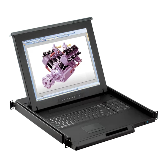
User Manual
Widescreen LCD Display
Wide 19", 22" screen size
Widescreen LCD Display
Models
RP-W822
RP-W719
4:3 LCD Display
15", 17", 19", 20" screen size
- BNC + S-Video
Options :
- Audio
Widescreen LCD Drawer
Models
RP-W119
4:3 LCD Display
Models
RP-615 / RP-717 / RP-819 / RP-920
SP-717 / SP-819 / SP-920
4:3 LCD Drawer
Models
- For standard
RP-115 / RP-117 / RP-119 / RP-120
- For SUN Solaris
SP-117 / SP-119 / SP-120
- For Short depth version
RP-1415 / RP-1417 / RP-1419
- DVI
- Quad Display
- Touchscreen
- DC power
Advertisement
Table of Contents

Related Manuals for Austin Hughes Electronics CyberView RP-615


Summary of Contents for Austin Hughes Electronics CyberView RP-615
-
Page 1: User Manual
User Manual Widescreen LCD Display Wide 19", 22" screen size Widescreen LCD Display Models RP-W822 RP-W719 4:3 LCD Display 15", 17", 19", 20" screen size - BNC + S-Video Options : - Audio Widescreen LCD Drawer Models RP-W119 4:3 LCD Display Models RP-615 / RP-717 / RP-819 / RP-920 SP-717 / SP-819 / SP-920... -
Page 2: Table Of Contents
Chapter 1 Getting Started Important Safeguards...1 Regulatory Notice...2 Before Installation...3 Unpacking...3 Optional Accessories...3 Peripheral Products...4 Part 1 Widescreen LCD Display Chapter 2 RP-W719 & RP-W822 Package Contents...5 Structure Diagram...6 Installation...7-8 Connection...9 Chapter 3 RP-W119 Package Contents...10 Structure Diagram...11 How to Use the Slides...12 Connection...13 Chapter 4 Operation... - Page 3 Part 2 4:3 LCD Display Chapter 6 RP-615, RP-717, RP-819 & RP-920 SP-717, SP-819 & SP-920 Chapter 7 RP-120 SP-120 RP-115, RP-117 & RP-119 SP-117 & SP-119 RP-1415, RP-1417 & RP-1419 Chapter 8 Operation Chapter 9 Optional Specifi cation Chapter 10 LCD Specifi cation Chapter 11 Troubleshooting Chapter 12 Dimensions Package Contents...24...
-
Page 4: Important Safeguards
1.1 Important Safeguards Please read all of these instructions carefully before you use the device. Save this manual for future reference. What the warranty does not cover ■ Any product, on which the serial number has been defaced, modifi ed or removed. ■... -
Page 5: Regulatory Notice
1.2 Regulatory Notice Legal Information First English printing, October 2002 Information in this document has been carefully checked for accuracy; however, no guarantee is given to the correctness of the contents. The information in this document is subject to change without no- tice. -
Page 6: Before Installation
1.3 Before Installation ■ It is very important to locate the Rackmount LCD Drawer / Display in a suitable environment. ■ The surface for placing and fi xing the Rackmount LCD Drawer / Display should be stable and level or mounted into a suitable cabinet. -
Page 7: Peripheral Products
1.6 Peripheral Products Item Model No. MU-1602 / MU-1603 / MU-1604 MU-IP1613 / MU-IP1614 / MU-IP1624 Matrix Cat6 KVM MU-3202 / MU-3203 / MU-3204 MU-IP3213 / MU-IP3214 / MU-IP3224 M-802 / M-803 / M-804 M-IP813 / M-IP814 / M-IP824 Matrix DB-15 KVM M-1602 / M-1603 / M-1604 M-IP1613 / M-IP1614 / M-IP1624 U-801 / U-802 / U-IP802... -
Page 8: Package Contents
2.1 Package Contents RP-W719 & RP-W822 Rackmount LCD display x 1 pc 6' VGA cable (male to male) x 1 pc User manual x 1 pc Power cord x 1 pc Auto switch power adapter x 1 pc Chapter 2... -
Page 9: Structure Diagram
2.2 Structure Diagram RP-W719 & RP-W822 Front view LCD interchangeable module kit LCD membrane Power adapter bracket Rear view Chapter 2 Power adapter Power cord... -
Page 10: Installation
Chapter 2 2.3 Installation RP-W719 ■ Install each screws shown in Figure 1. Figure 1. ■ Fixed the LCD into the rack. * M6 screws is not provided. Figure 2. -
Page 11: Installation
2.3 Installation RP-W822 Figure 3. ■ Install each screws shown in Figure 3. * M6 screws is not provided. Figure 5. ■ Push the lower part of the LCD into the rack. Figure 4. ■ Insert the upper part of the LCD display to the rack shown in Figure 4. -
Page 12: Connection
Chapter 2 2.4 Connection RP-W719 & RP-W822 DB-15 VGA female connector Power input The Rackmount LCD Drawer & Display are hot-pluggable, but components of Caution : connected devices, such as the servers and KVM switch, may not be hot-pluggable. Plug- ging and unplugging cables while servers and KVM are powered on may cause irreversible damage of the servers, KVM and Rackmount LCD Drawer. -
Page 13: Rp-W119
3.1 Package Contents RP-W119 LCD drawer x 1 pc 6’ VGA cable (male to male) x 1 pc User manual x 1 pc Power cord x 1 pc Mounting bracket x 2 pcs M6*15mm screw x 8 pcs M6 cage nut x 8 pcs M6 washer x 8 pcs P.10 Chapter 3... -
Page 14: Structure Diagram
3.2 Structure Diagram RP-W119 LCD interchangeable module kit “One Man” Installation Slide LCD membrane Carry handle to release the 2-pt lock 2-point lock P.11 Chapter 3... -
Page 15: How To Use The Slides
3.3 How to Use the Slides RP-W119 Figure 7. Figure 8. Figure 9. ■ A black arrow release button is located on the outside of each slide. (shown in Figure 7). ■ Pull and hold the black arrow button on either side of the LCD drawer to unlock. -
Page 16: Connection
3.4 Connection RP-W119 Power The Rackmount LCD Drawer & Display are hot-pluggable, but components of Caution : connected devices, such as the servers and KVM switch, may not be hot-pluggable. Plug- ging and unplugging cables while servers and KVM are powered on may cause irreversible damage of the servers, KVM and Rackmount LCD Drawer. -
Page 17: On-Screen Display Operation
4.1 On-screen Display Operation RP-W719 & RP-W822 RP-W119 Power light Green = On Orange = Power saving Power on / off LCD Display the OSD menu Scrolls through menu options and adjusts the displayed control Exit the OSD screen Shortcut key to auto adjustment by pressed the button for 5 seconds Toggle analog, digital &... -
Page 18: On-Screen Menu
4.2 On-screen Menu RP-W719, RP-W822 & RP-W119 Select: OSD Confi guration Page 1024 x 768 59.8Hz Image Brightness Contrast Color Temp User Green Blue Adjust: Set: Image: To enter into the brighness, contrast, color temp, red, green, and blue Geometry: To enter into the auto adjust, H position, V position, phase and clock Video:... -
Page 19: Dvi-D Option
Chapter 5 5.1 DVI-D Option RP-W719 & RP-W822 DVI-D Power RP-W119 DVI-D Remarks ■ Package includes 1 x 6ft DVI-D cable P.16... -
Page 20: Bnc + S-Video Option
5.2 BNC + S-Video Option RP-W719 & RP-W822 RP-W119 Remarks ■ Package includes 1 x 6ft S-Video cable S-Video BNC S-Video BNC P.17 Chapter 5 Power... -
Page 21: Audio Option
5.3 Audio Option RP-W719 & RP-W822 RP-W119 Power Audio Remarks: ■ Audio input is 35mm audio plug ■ The speaker is sharing the same power with LCD. Speaker Speaker P.18 Chapter 5... -
Page 22: Touchscreen Options
5.4 Touchscreen Options RP-W719 & RP-W822 USB interface Serial interface RP-W119 USB interface Power Serial interface Power Serial Serial P.19 Chapter 5 Power Power... - Page 23 5.4 Touchscreen Options e-Resistive Model Screen size Interface Optical transmittance Surface hardness Operating system e-Capacitive Model Screen size Interface Optical transmittance Surface hardness Operating system Remarks ■ USB touchscreen package includes 1 x 6ft USB cable, quick reference guideline and CD disc ■...
-
Page 24: Front Nema / Ip65 Option
5.5 Front NEMA 4 / IP65 Option RP-W719 & RP-W822 Rear case LCD panel 4mm protective glass (Front NEMA 4 / IP65 protection) Aluminum front panel Remarks ■ 4mm thickness of protective glass is not toughened one, please handle it carefully. P.21 Chapter 5... -
Page 25: Quad Display Option
5.6 Quad Display Option Specifi cations RS-232 VCR in Alarm I/O VCR out Item Model Number Number of Color Imaging System Resolution Refresh Rate Camera Input Video Input VCR Input Live Monitor Video Output Loop Through Out VCR Output Auto Gain Control Time / Date On Screen Display Camera Title... -
Page 26: Dc Power Options
5.7 DC Power Options RP-W719 & RP-W822 RP-W119 Model Input rating Input voltage: Input range: Input current - No load - Full load Output rating Output voltage: Output current: Effi ciency Remarks ■ Package does not include power cord and AC power adapter DC Power input DC Power input 12-Volt... -
Page 27: Chapter 6 Rp-615, Rp-717, Rp-819 & Rp
6.1 Package Contents RP-615, RP-717, RP-819 & RP-920 SP-717, SP-819 & SP-920 Rackmount LCD display x 1 pc 6' VGA cable (male to male) x 1 pc User manual x 1 pc Power cord x 1 pc Auto switch power adapter x 1 pc P.24 Chapter 6... -
Page 28: Structure Diagram
6.2 Structure Diagram RP-615, RP-717, RP-819 & RP-920 SP-717, SP-819 & SP-920 Front view LCD interchangeable module kit LCD membrane Power adapter bracket Rear view For 15" LCD P.25 Chapter 6 Power adapter Power cord... -
Page 29: Installation
Chapter 6 6.3 Installation RP-615, RP-717 & RP-819 SP-717 & SP-819 ■ Install each screws shown in Figure 10. Figure 10. ■ Fixed the LCD into the rack. * M6 screws is not provided. Figure 11. P.26... -
Page 30: Installation
Chapter 6 6.3 Installation RP-920 & SP-920 ■ Install each screws shown in Figure 12. Figure 12. ■ Fixed the LCD into the rack. * M6 screws is not provided. Figure 13. P.27... -
Page 31: Connection
6.4 Connection RP-615, RP-717, RP-819 & RP-920 SP-717, SP-819 & SP-920 DB-15 VGA female connector The Rackmount LCD Drawer & Display are hot-pluggable, but components of Caution : connected devices, such as the servers and KVM switch, may not be hot-pluggable. Plug- ging and unplugging cables while servers and KVM are powered on may cause irreversible damage of the servers, KVM and Rackmount LCD Drawer. -
Page 32: Package Contents
7.1 Package Contents RP-120 & SP-120 RP-115, RP-117, RP-119, SP-117 & SP-119 RP-1415, RP-1417 & RP-1419 LCD drawer x 1 pc 6’ VGA cable (male to male) x 1 pc User manual x 1 pc Auto switch power adapter ( for external power version) x 1 pc Power cord x 1 pc Mounting bracket x 2 pcs M6*15mm screw x 8 pcs... -
Page 33: Structure Diagram
7.2 Structure Diagram RP-120 & SP-120 RP-115, RP-117, RP-119, SP-117 & SP-119 RP-1415, RP-1417 & RP-1419 LCD interchangeable module kit “One Man” Installation Slide LCD membrane Carry handle to release the 2-pt lock 2-point lock P.30 Chapter 7... -
Page 34: How To Use The Slides
7.3 How to Use the Slides RP-120 & SP-120 RP-115, RP-117, RP-119, SP-117 & SP-119 RP-1415, RP-1417 & RP-1419 Figure 14. Figure 15. Figure 16. ■ A black arrow release button is located on the outside of each slide. (shown in Figure 14). ■... -
Page 35: Connection
7.4 Connection RP-120 & SP-120 RP-115, RP-117, RP-119, SP-117 & SP-119 RP-1415, RP-1417 & RP-1419 Internal power version Power External power version ( For short depth version - RP-1415 / 1417 / 1419 ) The Rackmount LCD Drawer & Display are hot-pluggable, but components of Caution : connected devices, such as the servers and KVM switch, may not be hot-pluggable. -
Page 36: On-Screen Display Operation
8.1 On-screen Display Operation RP-120 & SP-120 RP-115, RP-117, RP-119, SP-117 & SP-119 RP-1415, RP-1417 & RP-1419 15" LCD membrane 17", 19" & 20" LCD membrane Power light Green = On Orange = Power saving Power on / off LCD Display the OSD menu Scrolls through menu options and adjusts the displayed control Exit the OSD screen... -
Page 37: On-Screen Menu
8.2 On-screen Menu RP-120 & SP-120 RP-115, RP-117, RP-119, SP-117 & SP-119 RP-1415, RP-1417 & RP-1419 Select: OSD Confi guration Page 1024 x 768 59.8Hz Image Brightness Contrast Color Temp User Green Blue Adjust: Set: Image: To enter into the brighness, contrast, color temp, red, green, and blue Geometry: To enter into the auto adjust, H position, V position, phase and... -
Page 38: Dvi-D Option
9.1 DVI-D Option RP-615, RP-717, RP-819 & RP-920 SP-717, SP-819 & SP-920 Remarks ■ Package includes with 1 x 6ft DVI-D cable RP-120 & SP-120 RP-115, RP-117, RP-119, SP-117 & SP-119 RP-1415, RP-1417 & RP-1419 Internal power version External power version ( For short depth version - RP-1415 / 1417 / 1419 ) Remarks ■... -
Page 39: Bnc + S-Video Option
Chapter 9 9.2 BNC + S-Video Option RP-615, RP-717, RP-819 & RP-920 S-Video BNC Power RP-120 RP-115, RP-117 & RP-119 RP-1415, RP-1417 & RP-1419 Internal power version S-Video BNC External power version ( For short depth version - RP-1415 / 1417 / 1419 ) Remarks ■... -
Page 40: Audio Option
9.3 Audio Option RP-615, RP-717, RP-819 & RP-920 Audio Remarks ■ Audio input is 35mm audio plug ■ The speaker is sharing the same power with LCD. Power P.37 Chapter 9 Speaker... - Page 41 9.3 Audio Option RP-120 RP-115, RP-117 & RP-119 RP-1415, RP-1417 & RP-1419 Internal power version Power Audio External power version ( For short depth version - RP-1415 / 1417 / 1419 ) Remarks: ■ Audio input is 35mm audio plug ■...
-
Page 42: Touchscreen Options
9.4 Touchscreen Options RP-615, RP-717, RP-819 & RP-920 USB interface Serial interface RP-120 RP-115, RP-117 & RP-119 RP-1415, RP-1417 & RP-1419 USB interface Power Internal power version ( For short depth version - RP-1415 / 1417 / 1419 ) External power version Serial interface Power Internal power version... -
Page 43: Touchscreen Options
9.4 Touchscreen Options e-Resistive Model -15TRB / -15TRS Screen size Interface Optical transmittance Surface hardness Operating system e-Capacitive Model -15TCB / -15TCS Screen size Interface Optical transmittance Surface hardness Operating system Remarks ■ USB touchscreen package includes 1 x 6ft USB cable, quick reference guideline and CD disc ■... -
Page 44: Front Nema / Ip65 Option
9.5 Front NEMA 4 / IP65 Option RP-615, RP-717, RP-819 & RP-920 Rear case LCD panel 4mm protective glass (Front NEMA 4 / IP65 protection) Aluminum front panel Remarks ■ 4mm thickness of protective glass is not toughened one, please handle it carefully. P.41 Chapter 9... -
Page 45: Quad Display Option
9.6 Quad Display Option Specifi cations RS-232 VCR in Alarm I/O VCR out Item Model Number Number of Color Imaging System Resolution Refresh Rate Camera Input Video Input VCR Input Live Monitor Video Output Loop Through Out VCR Output Auto Gain Control Time / Date On Screen Display Camera Title... -
Page 46: Dc Power Options
9.7 DC Power Options RP-615, RP-717, RP-819 & RP-920 SP-717, SP-819 & SP-920 RP-120 & SP-120 RP-115, RP-117, RP-119, SP-117 & SP-119 RP-1415, RP-1417 & RP-1419 Model Input rating Input voltage: Input range: Input current - No load - Full load Output rating Output voltage: Output current:... -
Page 47: Lcd Specifications
10.1 LCD Specifi cations RP-W719, RP-W822 & RP-W119 Item LCD Manufacturer Diagonal Size Max. Resolution Brightness (cd/m²) Color Support Contrast Ratio (typ.) Viewing Angle (H/V) Display Area (mm) Tr Response Time (ms) LCD Panel MTBF (hrs) VGA Signal Input Sync. Type Resolution Plug &... - Page 48 10.1 LCD Specifi cations RP-120 RP-1415, RP-1417 & RP-1419 Item LCD Manufacturer Diagonal Size Max. Resolution Brightness (cd/m²) Color Support Contrast Ratio (typ.) Viewing Angle (H/V) Display Area (mm) Tr Response Time (ms) LCD Panel MTBF (hrs) VGA Signal Input Sync.
- Page 49 10.1 LCD Specifi cations SP-120 SP-717, SP-819 & SP-920 Item Form Factor Diagonal Size Resolution Brightness (cd/m²) Color Support Contrast Ratio (typ.) Viewing Angle (H/V) Display Area (mm) Tr Response Time (ms) LCD Panel MTBF (hrs) VGA Signal Input Sync. Type Resolution Plug &...
-
Page 50: Chapter 11 Troubleshooting
11.1 Troubleshooting 1. How do I adjust the resolution? To change monitor resolution, click Start -> Control Panel -> Display. Select Setting tab to adjust the monitor resolution in Desktop Area. The available resolutions, "640 x 480", "800 x 600", "1024 x 768", "1152 x 864", "1280 x 1024", are deter- mined by the display card in your computer. -
Page 51: Chapter 12 Dimensions
12.1 Dimensions RP-W719, RP-W822 & RP-W119 RP-615, RP-717, RP-819 & RP-920 SP-717, SP-819 & SP-920 Product Dimension Model (W x D x H) 480 x 57.5 mm RP-W719 18.9 x 2.3" 500.4 x 59.1 mm RP-W822 19.7 x 2.3" 445 x 650 x 44 mm RP-W119 17.5 x 25.6 x 1.73"... - Page 52 The company reserves the right to modify product specifi cations without prior notice and assumes no responsibility for any error which may appear in this publication. All brand names, logo and registered trademarks are properties of their respective owners. Copyright 2008 Austin Hughes Electronics Ltd. All rights reserved. Packing Dimension Net Weight...
Need help?
Do you have a question about the CyberView RP-615 and is the answer not in the manual?
Questions and answers