Table of Contents
Advertisement
Quick Links
Installation & Operation Manual
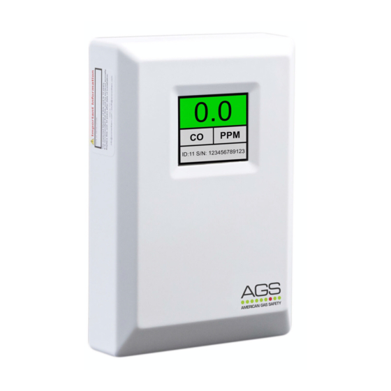
Merlin Gas Detector TFT
At American Gas Safety, we supply a full range of remote gas detectors including carbon monoxide (CO),
natural gas (NG) and liquid petroleum gas (LPG) that are compatible with our range of Merlin panels.
The information contained within this manual should be referenced for typical installation and operation
only. For specific requirements that may deviate from the information in this guide – contact your supplier.
AGSDETTFT-IOM Iss: 5 06-20
Installation & Operation Manual
Please read this manual carefully and retain for future use.
Merlin Gas Detector TFT
1
Advertisement
Table of Contents

Related Manuals for AGS Merlin TFT


Summary of Contents for AGS Merlin TFT
- Page 1 Installation & Operation Manual Merlin Gas Detector TFT Merlin Gas Detector TFT Installation & Operation Manual Please read this manual carefully and retain for future use. At American Gas Safety, we supply a full range of remote gas detectors including carbon monoxide (CO), natural gas (NG) and liquid petroleum gas (LPG) that are compatible with our range of Merlin panels.
-
Page 2: Table Of Contents
Installation & Operation Manual Merlin Gas Detector TFT CONTENTS INSTALLATION ................... 3 Planning ........................... 3 Typical Location and Positioning ................3 Typical Installation Arrangement ................4 Fixing ..........................4 Board Overview ......................5 Wiring the Detector ....................... 5 Merlin -X- Systems ......................5 Merlin -S- Systems...................... -
Page 3: Installation
Installation & Operation Manual Merlin Gas Detector TFT INSTALLATION Planning Our detectors should be installed in areas at risk of gas leaks e.g. over boilers, valves or meters. Take in to account the design of the air flow patterns within the zone area. Detectors should be installed in the correct orientation, as recommended by the manufacturer, and ease of access should be accounted for to allow for any bump tests, recalibration and other forms of maintenance. -
Page 4: Typical Installation Arrangement
Installation & Operation Manual Merlin Gas Detector TFT Typical Installation Arrangement Many detection systems are designed around a centralised control unit of which the location also needs to be considered. They should be located outside of the hazardous area that they are monitoring. -
Page 5: Board Overview
Installation & Operation Manual Merlin Gas Detector TFT Board Overview Do not attempt to remove the Circuit Board! This will void any warranty. Wiring the Detector Merlin -X- Systems 12-24V Power and data supply via [DETECTOR X CHAIN] terminal and Merlin GDP-X range terminal [DETECTOR CHAIN]. - Page 6 Installation & Operation Manual Merlin Gas Detector TFT Multiple Detector Chain System - Typical Wiring Example Chain System Termination Switches 120ohm Chain Termination Resistor Switch Signal communication issues may occur where the bus length is too long or high baud rates are used. In this instance – terminating at each end of the chain may help the quality of the data signal.
-
Page 7: Merlin -S- Systems
Installation & Operation Manual Merlin Gas Detector TFT Merlin -S- Systems 12-24V power supply via Power Input [+ -] and ‘S’ panel [GAS DETECTOR] terminal. Building Management Systems (BMS) If you are connecting to ‘S’ range you will need to use [NC/COM] terminals as an alarm relay. These are volt free connections to building management systems. -
Page 8: Chain Id Switches
Installation & Operation Manual Merlin Gas Detector TFT X Chain ID Switches When wiring multiple detectors to the GDP-X range it is important to identify each detector and in which monitoring zone the detector is located - for the GDP-X system to receive and display accurate data. -
Page 9: Trouble Shooting
Installation & Operation Manual Merlin Gas Detector TFT Trouble Shooting Fault. Possible Cause/Correction. Incorrect wiring. Detector not responding. ID switches not properly configured. Termination switches not set up correctly. Fault message on screen Gas sensor element knocked or damaged. Service message on screen Detector requires service –... -
Page 10: Operation
Installation & Operation Manual Merlin Gas Detector TFT OPERATION First Power Up On connecting power, the detector enters ‘sensor stabilisation’ phase for approximately 60 seconds – during this period the screen will display an ‘initialisation’ message indicating that the device is not yet ready for gas detection. When the sensor has stabilised –... -
Page 11: Testing The System
Installation & Operation Manual Merlin Gas Detector TFT Testing the System There is a [TEST] button on the Detector circuit board. When the test button is pressed and held – the detector will simulate an open circuit to ensure all systems, alarms, indications and other external devices operate as intended. -
Page 12: Bump Testing
Installation & Operation Manual Merlin Gas Detector TFT Bump Testing What is Bump Testing? Bump testing is a term used for checking a gas detector is functioning correctly by exposing it to the target gas. A known concentration of the target gas is applied to the device to trigger an alarm condition and ascertain the detector is working safely. -
Page 13: Important Warning Statements
Installation & Operation Manual Merlin Gas Detector TFT IMPORTANT WARNING STATEMENTS Please take the time to thoroughly read this user’s guide which should be retained for future reference. The expected lifetime of gas sensor elements is 3-10 years upon initial power up dependant on your target gas and other environmental factors. - Page 14 Installation & Operation Manual Merlin Gas Detector TFT NOTES AGSDETTFT-IOM Iss: 5 06-20...
- Page 15 Installation & Operation Manual Merlin Gas Detector TFT NOTES AGSDETTFT-IOM Iss: 5 06-20...
-
Page 16: Installation Details
Organisation: Stamp/ Signature of the installer: Replacement Date: CONTACT US: AGS Head Office Tel: (727) 608-4375 Fax: (727) 538-4237 info@americangassafety.com American Gas Safety is the owner of this document and reserves all rights of modification without prior notice. AGSDETTFT-IOM Iss: 5 06-20...
Need help?
Do you have a question about the Merlin TFT and is the answer not in the manual?
Questions and answers