Table of Contents
Advertisement
Quick Links
USER'S MANUAL
Of
Intel P67 Express Chipset
Based
M/B for Intel LGA 1155 Processors
NO. G03-HI08-F
Rev: 1.0
Release in: December, 2010
Trademark:
* Specifications and Information contained in this documentation are furnished for information use only, and are
subject to change at any time without notice, and should not be construed as a commitment by manufacturer.
Advertisement
Table of Contents

Related Manuals for Intel P67


Summary of Contents for Intel P67
- Page 1 USER'S MANUAL Intel P67 Express Chipset Based M/B for Intel LGA 1155 Processors NO. G03-HI08-F Rev: 1.0 Release in: December, 2010 Trademark: * Specifications and Information contained in this documentation are furnished for information use only, and are subject to change at any time without notice, and should not be construed as a commitment by manufacturer.
- Page 2 Environmental Protection Announcement Do not dispose this electronic device into the trash while discarding. To minimize pollution and ensure environment protection of mother earth, please recycle.
-
Page 3: Table Of Contents
USER’S NOTICE ........................iv MANUAL REVISION INFORMATION ..................iv ITEN CHECK LIST ........................iv COOLING SOLUTIONS ......................iv CHAPTER 1 INTRODUCTION OF P67 EXPRESS CHIPSET MOTHERBOARDS MOTHERBOARD SPECIFICATION ................1 SPECIAL FEATURES OF MOTHERBOARD............. 2 LAYOUT DIAGRAM....................3 CHAPTER 2 HARDWARE INSTALLATION HARDWARE INSTALLATION STEPS ............... -
Page 4: Enviromental Safety Instruction
Environmental Safety Instruction Avoid the dusty, humidity and temperature extremes. Do not place the product in any area where it may become wet. 0 to 40 centigrade is the suitable temperature. (The figure comes from the request of the main chipset) Generally speaking, dramatic changes in temperature may lead to contact malfunction and crackles due to constant thermal expansion and contraction from the welding spots’... -
Page 5: User's Notice
In addition, interface materials allow effective transfers of heat from the processor to the heat sink. For optimum heat transfer, Intel recommends the use of thermal grease and mounting clips to attach the heat sink to the processor. -
Page 6: Motherboard Specification
Design ATX form factor; PCB size: 30.5x24.5cm Chipset Intel P67 Express Chipset Intel LGA 1155 socket Intel® Core™ i7 Processor, Intel® Core™ i5 CPU Socket Processor, Intel® Core™ i3 Processor for detailed CPU support information please visit our website DDRIII module sockets x 4... -
Page 7: Special Features Of Motherboard
1-2 Special Features of motherboard CPU Smart Fan—The Noise Management System It’s never been a good idea to gain the performance of your system by sacrificing its acoustics. CPU Smart Fan Noise Management System is the answer to control the noise level needed for now-a-day’s high performance computing system. -
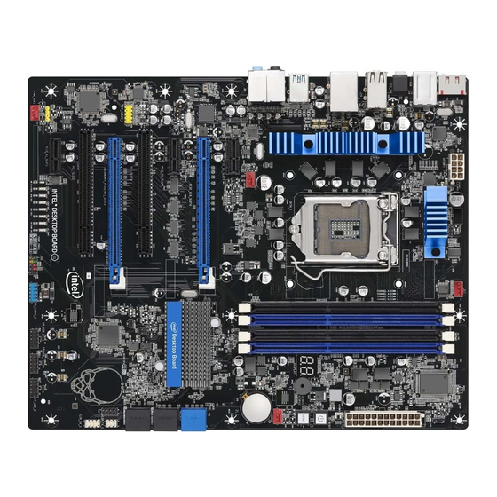
Page 8: Layout Diagram
ATX Power Conn. RJ-45 Over USB 2.0 Ports 8-CH HD 64MB Flash ROM Audio Connector SYSFAN Intel P67 Chipset PCI Express2.0 x1 Gigabit LAN Chip PCI Express 2.0 x16 by 16 Lane JBAT 8-CH HD PCI Express 2.0 x16 by 8 Lane... -
Page 9: Chapter 2 Hardware Installation
Chapter 2 Hardware Installation WARNING! Turn off your power when adding or removing expansion cards or other system components. Failure to do so may cause severe damage to both your motherboard and expansion cards. Hardware installation Steps Before using your computer, you had better complete the following steps: 1. -
Page 10: Installing Cpu
2-3 Closed: KB/MS Power ON Enabled KB/MS Power On Setting Installing CPU 2-3-1 About Intel LGA 1155 CPU Socket This motherboard provides an 1155-pin DIP, LGA 1155 Land Grid Array socket, referred to as the LGA 1155 socket. The CPU that comes with the motherboard should have a cooling FAN attached to prevent overheating. -
Page 11: Lga 1155 Cpu Installation Guide
2-3-2 LGA 1155 CPU Installation Guide Please make sure that CPU socket is facing Press down the level and move it to the left side to make sure it is freed from the hook and then towards you and the level is on you left hand open it upwards about 135 degree. -
Page 12: Intel Reference Thermal Solution Assembly
The heat sink and installation steps are for reference use only; Installation steps might differ depending on different heat sink models. Please use Intel original heat sink for better heat dissipation or other heat sinks that has pass Intel certification. -
Page 13: Install Memory
Install Memory This motherboard provides four 240-pin DDR III DUAL INLINE MEMORY MODULES (DIMM) socket for DDR III memory expansion available to maximum memory volume of 16GB DDRIII SDRAM. Valid Memory Configurations Bank 240-Pin DIMM Maximum Capacity DIMM1 DDRIII 1066/ DDRIII 1333 DIMM2 DDRIII 1066/ DDRIII 1333 DIMM3... -
Page 14: Expansion Cards Installation
Expansion Card Installation 2-5-1 Expansion Slot The P67 Express chipset based motherboard series offer one PCI-Express 2.0 x16 by 16 lane, one PCI-Express 2.0 x16 by 8 lane and one PCI-Express 2.0 x16 by 4 lane graphics slots. These two graphics slots support the latest AMD CrossFireX Technology and nVidia SLI to guarantee the fully operational Multi-GPUs graphics function and avoid the possible installation error. -
Page 15: Installing Crossfire/Sli Card Bridge
2-5-3 Installing the CrossFire /SLI Bridge Card The following illustrations show you how to install the Bridge Card. In order to activate the CrossFire/SLI technology, you have to install the optional bridge card for your CrossFire /SLI Tech. Supported VGA Cards before you activating the advance multi-GPUs functions. -
Page 16: Connectors And Headers
2-6 Connectors and Headers 2-6-1 I/O Back Panel Connectors RJ-45 LAN Port Line-IN USB 2.0 Ports USB 3.0 Port RS-OUT Optical S/PDIF_OUT Line-OUT CS-OUT SS-OUT MIC-IN Coaxial CMOS Clear USB 2.0 Ports USB 2.0 Ports S/PDIF_OUT Button PS/2 Keyboard Port (1) Coaxial SPDIF Out connectors: SPDIF_OUT1 This coaxial S/PDIF connector is provided to transmit digital audio signals to speaker by connecting a coaxial S/PDIF cable. -
Page 17: I/O Back Panel Connectors
2-6-2 Internal Connectors (1) Power Connector (24-pin block): ATXPWR1 ATX Power Supply connector: This is a new defined 24-pins connector that usually comes with ATX case. The ATX Power Supply allows using soft power on momentary switch that connect from the front panel switch to 2-pins Power On jumper pole on the motherboard. - Page 18 (2) ATX 12V Power Connector (8-pin block) : ATX12V1 This is a new defined 8-pin connector that usually comes with ATX Power Supply. The ATX Power Supply which fully supports LGA 1155 processor must including this connector for support extra 12V voltage to maintain system power consumption.
-
Page 19: Internal Headers And Others
2-6-3 Internal Headers and Others (1) Line-Out/MIC Header for Front Panel (9-pin): FP_AUDIO These headers connect to Front Panel Line-out, MIC connector with cable. AU D I O P in 1 L ine-O ut, MIC Headers (2) CD Audio-In Headers (4-pin): CDIN CDIN are the connectors for CD-Audio Input signal. - Page 20 (6) IDE Activity LED: HD LED This header connects to the hard disk activity indicator light on the case. (7) Reset switch lead: RESET This 2-pin header connects to the case-mounted reset switch for rebooting your computer without having to turn off your power switch. See the figure below. (8) Power switch: PWR BTN This 2-pin header connects to the case-mounted power switch to power ON/OFF the system.
- Page 21 (11) Parallel COM Port header: PARALLEL The board also provides a 25-pin parallel port header. Pin 2 Pin 1 Parallel Header (12) FAN Headers: SYSFAN1 (3-pin), SYSFAN2 (3-pin), CPUFAN (4-pin) These connectors support cooling fans of 350mA (4.2 Watts) or less, depending on the fan manufacturer, the wire and plug may be different.
-
Page 22: Chapter 3 Introducing Bios
Chapter 3 Introducing BIOS The BIOS is a program located on a Flash Memory on the motherboard. This program is a bridge between motherboard and operating system. When you start the computer, the BIOS program will gain control. The BIOS first operates an auto-diagnostic test called POST (power on self test) for all the necessary hardware, it detects the entire hardware device and configures the parameters of the hardware synchronization. -
Page 23: Function Keys
Function Key In the above BIOS Setup main menu of, you can see several options. We will explain these options step by step in the following pages of this chapter, but let us first see a short description of the function keys you may use here: Press←→... -
Page 24: Advanced Menu
System Language Choose the system default language. The optional settings are: [English]; [Chinese]. System Date Set the date. Please use TAB to switch between data elements. System Time Set the date. Please use TAB to switch between time elements. 3-7 Advanced Menu... - Page 25 This item should be set as [Disabled] for Windows XP. Execute Disable Bit The optional settings: [Enabled]; [Disabled]. Intel Virtualization Technology The optional settings: [Enabled]; [Disabled]. When set as [Enabled], a VHM can utilize the additional hareware capabilities provided by Vanderpool Technology.
- Page 26 The optional settings: [Enabled]; [Disabled]. Power Limit 2 Value Use this item to set power limit 2value (Matt) from 0 to 500. Enhanced Intel SpeedStep Technology The optional settings: [Enabled]; [Disabled]. Turbo Mode Use this item to enable or disable turbo mode.
- Page 27 Use this item to set internal write to read command delay. Active to Active Delay (tRRD) Use this item to set row active to row active delay. Read CAS# Precharege (tRTP) Use this item to set read to precharge delay. Four Active Windows Delay (tFAW) Use this item to set four active windows delay.
-
Page 28: Chipset Menu
► H/W Monitor Shutdown Temperature Use this item to select system shutdown temperature. CPUFAN1 Smart Mode When set as [Enabled], the following sub-items shall appear: CPUFAN1 Highest Speed Temp/ CPUFAN1 Second Speed Temp Use these items to set CPUFAN1 Highest Speed Temp/ CPUFAN1 Second Speed Temp. - Page 29 ► North Bridge LOW MMIO Align The optional settings are: [64M]; [1024M]. DMI Gen2 The optional settings are: [Enabled]; [Disabled]. VT-d The optional settings are: [Enabled]; [Disabled]. PCI Express Port The optional settings are: [Auto]; [Enabled]; [Disabled]. PEQ Force Gen1 The optional settings are: [Enabled];...
-
Page 30: Boot Menu
► ME subsystem ME Subsystem/ME Temporary Disable/End of Post Message The optional settings are: [Enabled]; [Disabled]. Integrated Clock Chip Configuration Press enter to further set integrated clock chip sub-items. 3-9 Boot Menu Setup Prompt Timeout Use this item to set number of seconds to wait for setup activation key. Bootup Numlock State Use this item to select keyboard numlock state.The optional settings are: [On];... -
Page 31: Security Menu
3-10 Security Menu Security menu allow users to change administrator password and user password settings. 3-11 Save & Exit Menu Save & Exit menu allows user to load optimal defaults, save or discard your changes to BIOS items. -
Page 32: How To Update Bios
3-12 How to Update BIOS Solution1: Updating BIOS under DOS: 1. Prepare a bootable disk. (You may make one by click START click RUN type SYS click OK) 2. Download upgrade tools and the latest BIOS files of the motherboard from official website and then make a copy of it to your bootable floppy disk after decompressing these files 3. -
Page 33: Chapter 4 Driver & Free Program Installation
Chapter 4 Driver & Free Program Installation 4-1 Installation Instruction User need to install operating system before installing the drivers. Magic Install supports Windows XP/Vista/7. Take the attached DVD and insert it into DVD-ROM driver, the installation shall auto-run. If the menu does not appear, double-click MY COMPUTER / double-click CD-ROM drive or click START / click RUN / type X:\SETUP.EXE (assuming X is your CD-ROM drive). -
Page 34: Ahci/Raid Install Intel Ahci /Raid Driver
4-2 AHCI/RAID Install Intel AHCI /RAID Driver If you want to use Intel SATA AHCI mode for your system, please according to following steps to install driver: 1. Copy CD: \intel6x\pch_ahci_raid\f6flpy32 all files to empty boot disk root directory. (For windows XP / vistaX32) Copy CD: \intel6x\pch_ahci_raid\f6flpy64 all files to empty boot disk root directory. -
Page 35: Jetway Hammer Unique Overlock Tool
4-3 Jetway Hammer Unique Overlock Tool Jetway hammer unique overlock tool provides update zone, overlock zone, monitor zone and system information zone. Four powerful function zones that allow you to overlock your system efficiently. Please copy this software in support DVD that came with the motherboard package. -
Page 36: How To Use Jetway Hammer Unique Overlock Utility
, *According to your demand you can download: Manual, Driver or BIOS. Please update by yourself after downloading. 4-3-3 How to Use Jetway Hammer Unique Overlock Utility Click the “small triangle” of adjustment bars to adjust CPU ratio﹑voltage and memory voltage. -
Page 37: Monitor Zone
The dialogue box that reminds you whether continue overclocking will appear when you click the “small triangle” for the first time. Click “Yes” to continue or “No” to quit. “Glossary”: 1. Load Last Setting: Users can restore last optimal setting by this setting. 2. -
Page 38: Information Zone
sound will be made by loudspeaker of motherboard when system setting value exceeds default safety value. Overclock enthusiast could ignore some monitor selection to avoid excessive warning tips. The software would do nothing if choose to ignore. 4-3-5 Information Zone Information zone includes four parts: Memory Info, CPU Info, HDD Info, Motherboard Info.
Need help?
Do you have a question about the P67 and is the answer not in the manual?
Questions and answers