
Related Manuals for STATUS SCIENTIFIC CONTROLS FGD10B


Summary of Contents for STATUS SCIENTIFIC CONTROLS FGD10B
- Page 1 STATUS SCIENTIFIC CONTROLS Issue: Date: 7/1/20 Firmware: Installation, Commissioning & Routine Gas Testing Manual Gas Detector Type FGD10B Infrared Version 2 (with GSH4 Sensor)
- Page 3 Authorised Signatory to this declaration, on behalf of the manufacturer: Name: David Stuttard Title: Managing Director Address: Status Scientific Controls Ltd, Hermitage Lane Industrial Estate, Kings Mill Way Mansfield, Nottinghamshire, NG18 5ER, United Kingdom Signature Date: 14/10/19 Extract from TD18/100...
-
Page 6: Table Of Contents
STATUS SCIENTIFIC CONTROLS Installation, Commissioning & Routine Gas Testing FGD10B Infrared Gas Detector CONTENTS PACKAGE CONTENTS ..............8 SCOPE OF THE MANUAL ..............8 DESCRIPTION ..................9 3.1................10 AS TYPES INSTALLATION ................11 4.1................12 ABLE ENTRIES 4.2. - Page 7 STATUS SCIENTIFIC CONTROLS Installation, Commissioning & Routine Gas Testing FGD10B Infrared Gas Detector SENSOR REPLACEMENT ..............33 11.1..............33 NFRARED SENSOR FUSES ....................39 SPECIFICATION ................39 DIMENSIONS ..................40 CERTIFICATION ................41 TD18/006 Issue: Change Note: 1904 Page 7...
-
Page 8: Package Contents
An infrared sensor for the detection of Carbon dioxide. Note – Infrared sensors are unsuitable for the detection of Hydrogen. However, this gas can be detected using a version of the FGD10B fitted either with pellistors or suitable electro-chemical sensors. -
Page 9: Description
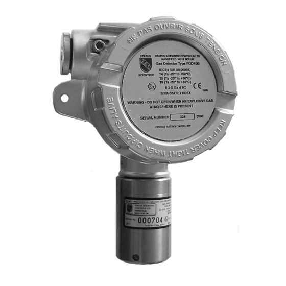
Installation, Commissioning & Routine Gas Testing FGD10B Infrared Gas Detector Description The FGD10B is an explosion protected ATEX and IECEx certified fixed gas detector for use in potentially explosive atmospheres. The infrared gas sensor is housed within a Type GSH4 certified flameproof housing, manufactured from stainless steel, attached to the main FGD10B enclosure. -
Page 10: Gas Types
Analogue output – 4 to 20mA dc • Gland entry threads available – 20mm, ½” or ¾” NPT 2.1. Gas types Versions of the FGD10B Infrared are available for detection of gases, fitted with any of the following sensor types:- • Infrared - Hydrocarbon •... -
Page 11: Installation
In order to prevent dangerous overloading of the FGD10B gas detector, it is fitted with an internal self resetting fuse which limits the maximum allowable power dissipation. -
Page 12: Cable Entries
The FGD10B should be mounted and secured using the mounting holes on the main unit. Figures 2 and 3 shows details of the FGD10B terminal connections – these can be accessed as follows:-. Switch OFF the supply to the FGD10B. -
Page 13: Fgd10B Connections
STATUS SCIENTIFIC CONTROLS Installation, Commissioning & Routine Gas Testing FGD10B Infrared Gas Detector FGD10B connections Figure 2 – Armoured Cable Gland Installation Figure 3 – EEx d Conduit Installation TD18/006 Issue: Change Note: 1904 Page 13... -
Page 14: Wiring Details
STATUS SCIENTIFIC CONTROLS Installation, Commissioning & Routine Gas Testing FGD10B Infrared Gas Detector 3.2. Wiring details 3.2.1. FGD10B Infrared The infrared gas detector is powered from a 8 – 24 volt dc, 5W maximum output supply with a separate connection for the 4 – 20 mA output and as such requires 3 wires, see following diagram. -
Page 15: Commissioning
The characteristics can be used as a guide when setting up the alarm levels in the associated control unit, e.g. where a general hydrocarbon response is required. b) The FGD10B can be fitted with a sensor that is characterised for different gases, contact Status Scientific Controls. TD18/006... - Page 16 STATUS SCIENTIFIC CONTROLS Installation, Commissioning & Routine Gas Testing FGD10B Infrared Gas Detector TD18/006 Issue: Change Note: 1904 Page 16...
-
Page 17: Initial Gas Testing
The FGD10B sensor should be allowed to stabilise for the period specified on the associated calibration certificate before attempting to check the zero setting and gas response. - Page 18 STATUS SCIENTIFIC CONTROLS Installation, Commissioning & Routine Gas Testing FGD10B Infrared Gas Detector Figure 7 – Arrangement for Application of a Certified Test Gas Sampling Adaptor 6mm OD Tubing Remote Sampling Point Flow regulator 1L/Min Certified Calibration Gas Cylinder TD18/006...
-
Page 19: Test Gas
O.D tubing. The connector is screwed into a 1/8” BSP thread; other fittings are available on request. Where a weather guard is not fitted, the use of a sampling adaptor (Stock No. SS336) is required in order to present the gas to the FGD10B sensor. TD18/006 Issue:... -
Page 20: Sampling Time
STATUS SCIENTIFIC CONTROLS Installation, Commissioning & Routine Gas Testing FGD10B Infrared Gas Detector 5.2.2. Sampling time Apply the test gas and allow a sufficient time for the sample to reach the gas detector. The response time will vary according to the length of the sampling tube. -
Page 21: Calibration
Calibration of the sensor can be carried out by using the buttons on the circuit board as seen in Fig1 and Fig 2. These buttons only work when the FGD10B Infrared has been powered for a minimum of 10 minutes. -
Page 22: Sensor Span
STATUS SCIENTIFIC CONTROLS Installation, Commissioning & Routine Gas Testing FGD10B Infrared Gas Detector 5.4. Sensor Span Always zero the sensor prior to performing a span operation. Fig 2 Span Apply a known concentration of gas (applicable to sensor type) at a flow rate of between 500 and 1000cc/min. -
Page 23: Calibration / Configuration Keypad
FGD10B Infrared Gas Detector 5.5. Calibration / Configuration Keypad The FGD10B infrared sensor can be calibrated via a purpose designed keypad. The keypad allows the user to carry out the following: calibrate the sensor. calibrate the 4 to 20 mA loop. - Page 24 FGD10B Infrared gas detector. Note: It is important that that the FGD10B is correctly configured for the sensor in use, prior to performing any feature available in the menu system.
-
Page 25: Menu Mode Selection
E : 5 – Output Span (20mA) E : 9 – Diagnostics E : 77 – Sensor Firmware version Several calibration modes exist in the FGD10B and these are accessible via the instruments simple menu system. To select a calibration mode follow this procedure: •... -
Page 26: E : 1 - Sensor Zero
E : 9 – Engineer diagnostics 5.6.6. This feature is a view-only feature. No configuration changes are possible from within this menu. The information is for use of Status Scientific Controls personnel. • From the menu system select menu option: E: 9 and press •... -
Page 27: E : 77 - Sensor Firmware Version
STATUS SCIENTIFIC CONTROLS Installation, Commissioning & Routine Gas Testing FGD10B Infrared Gas Detector E : 77 – Sensor Firmware Version 5.6.7. This feature is a view-only feature. No configuration changes are possible from within this menu. • From the menu system select menu option: E: 77 and press . -
Page 28: Calibration
STATUS SCIENTIFIC CONTROLS Installation, Commissioning & Routine Gas Testing FGD10B Infrared Gas Detector ALIBRATION MENU DOWN ENTER 6.1. Sensor Calibration This feature allows the sensor to be calibrated. Ensure that the correct sensor type is selected in the configuration prior to calibration. Refer to section 5.6. -
Page 29: Sensor Span
STATUS SCIENTIFIC CONTROLS Installation, Commissioning & Routine Gas Testing FGD10B Infrared Gas Detector 6.1.2. Sensor Span Always zero the sensor prior to performing a span operation. • From the menu system select menu option: E: 2 and press • Apply a known concentration of gas (applicable to sensor type) at a flow rate of between 500 and 1000cc/min. -
Page 30: Analogue Output Calibration
Meter range: – Control Analogue Output 0.04V – 0.20V Unit (4 – 20mA) 40mV – 200mV Advantage: No need to disturb wiring between FGD10B and control unit. Disadvantage: Measurement accuracy dependent upon resistor tolerance. TD18/006 Issue: Change Note: 1904 Page 30... -
Page 31: Analogue Output Zero
FGD10B Infrared Gas Detector 6.2.1. Analogue Output Zero • Monitor the current sourced from the analogue output of the FGD10B using a suitable method. • From the menu system select menu option: E: 4 and press • Using the buttons; adjust the output to the required level (4mA or 40mV). -
Page 32: Routine Gas Testing
6.1.2. . Carrying out the above procedure, and comparing the results with previous readings, will confirm that the FGD10B is functioning correctly, both physically and electrically. In the unlikely event that the response time is seen to be increasing, when comparing periodic readings, it is advisable to change the unit so that it can be checked. -
Page 33: Sensor Replacement
STATUS SCIENTIFIC CONTROLS Installation, Commissioning & Routine Gas Testing FGD10B Infrared Gas Detector ENSOR REPLACEMENT 8.1. Infrared sensor Step1 Remove the grub screw in an anti-clockwise direction. TD18/006 Issue: Change Note: 1904 Page 33... - Page 34 STATUS SCIENTIFIC CONTROLS Installation, Commissioning & Routine Gas Testing FGD10B Infrared Gas Detector Step 2 Turn sensor housing cover anti-clockwise to allow cover to open. TD18/006 Issue: Change Note: 1904 Page 34...
- Page 35 STATUS SCIENTIFIC CONTROLS Installation, Commissioning & Routine Gas Testing FGD10B Infrared Gas Detector Step 3 Remove the sensor by pulling downwards TD18/006 Issue: Change Note: 1904 Page 35...
- Page 36 STATUS SCIENTIFIC CONTROLS Installation, Commissioning & Routine Gas Testing FGD10B Infrared Gas Detector Step 4 Carefully locate the pins in the sockets then push the new sensor upwards. TD18/006 Issue: Change Note: 1904 Page 36...
- Page 37 STATUS SCIENTIFIC CONTROLS Installation, Commissioning & Routine Gas Testing FGD10B Infrared Gas Detector Step 5 Replace the sensor housing by rotating in a clockwise direction untill fully tightened. TD18/006 Issue: Change Note: 1904 Page 37...
- Page 38 STATUS SCIENTIFIC CONTROLS Installation, Commissioning & Routine Gas Testing FGD10B Infrared Gas Detector Step 6 Rotate the grub screw in a clockwise direction until fully tightened. TD18/006 Issue: Change Note: 1904 Page 38...
-
Page 39: Fuses
STATUS SCIENTIFIC CONTROLS Installation, Commissioning & Routine Gas Testing FGD10B Infrared Gas Detector USES A 340 mA ‘Multifuse’ is located within the FGD10B. It will automatically reset when normal conditions return. PECIFICATION Instrument Body – Aluminium Pressure Die Casting (Stainless Steel versions available, suffix –SS) Materials Sensor Housing –... -
Page 40: Dimensions
STATUS SCIENTIFIC CONTROLS Installation, Commissioning & Routine Gas Testing FGD10B Infrared Gas Detector IMENSIONS 108 Centres 2 x 7mm dia. mounting holes Optional Weatherguard Maximum Depth = 127mm TD18/006 Issue: Change Note: 1904 Page 40... -
Page 41: Certification
STATUS SCIENTIFIC CONTROLS Installation, Commissioning & Routine Gas Testing FGD10B Infrared Gas Detector ERTIFICATION The FGD10 Series of Gas Detectors are ATEX and IECEx certified for use in potentially explosive atmospheres and is marked as follows:- WARNING – DO NOT OPEN WHEN AN EXPLOSIVE GAS... - Page 42 STATUS SCIENTIFIC CONTROLS Installation, Commissioning & Routine Gas Testing FGD10B Infrared Gas Detector The cable entry devices and blanking elements of unused apertures shall be of a certified flameproof type, suitable for the conditions of use and correctly installed. With the use of conduit, a suitable certified sealing device such as a stopping box with compound shall be provided immediately at the entrance to the flameproof enclosure.
- Page 43 STATUS SCIENTIFIC CONTROLS Installation, Commissioning & Routine Gas Testing FGD10B Infrared Gas Detector USTOMER NOTES TD18/006 Issue: Change Note: 1904 Page 43...
Need help?
Do you have a question about the FGD10B and is the answer not in the manual?
Questions and answers