Table of Contents
Advertisement
Quick Links
Advertisement
Table of Contents

Related Manuals for STATUS SCIENTIFIC CONTROLS FGD2


Summary of Contents for STATUS SCIENTIFIC CONTROLS FGD2
- Page 1 STATUS SCIENTIFIC CONTROLS Issue: Date: 14/10/19 Version: 9.6P FGD2 & 3 Atex Flammable Gas Detector Heads STATUS SCIENTIFIC CONTROLS LTD. Hermitage Lane Industrial Estate, Kings Mill Way, Mansfield, Nottinghamshire. NG18 5ER England : 01623 651381 : 01623 421063...
- Page 3 Authorised Signatory to this declaration, on behalf of the manufacturer: Name: David Stuttard Title: Managing Director Address: Status Scientific Controls Ltd, Hermitage Lane Industrial Estate, Kings Mill Way Mansfield, Nottinghamshire, NG18 5ER, United Kingdom Signature Date: 14/10/19 Extract from TD06/110...
- Page 4 STATUS SCIENTIFIC CONTROLS FGD2 & 3 Flammable Gas Detector Heads FGD2 Atex Gas Detector Head FGD3 Atex Gas Detector Head...
-
Page 5: Table Of Contents
STATUS SCIENTIFIC CONTROLS FGD2 & 3 Flammable Gas Detector Heads INTRODUCTION ................1-1 ................1-1 NSTALLATION 1.1.1 Siting the Sensors ............... 1-1 1.1.2 Wire Termination ..............1-2 1.1.3 Cable Routing ..............1-2 1.1.4 Cable & Screening .............. 1-2 INSTALLATION IN A NON-HAZARDOUS LOCATION....2-1 . -
Page 6: Introduction
STATUS SCIENTIFIC CONTROLS FGD2 & 3 Flammable Gas Detector Heads NTRODUCTION The detectors use the industry standard 4-20mA current loop to convey the gas levels detected to a control unit. This means that under zero gas conditions 4mA is drawn from the supply, and under full scale gas conditions 20mA is drawn from the supply. -
Page 7: Wire Termination
STATUS SCIENTIFIC CONTROLS FGD2 & 3 Flammable Gas Detector Heads 1.1.2 Wire Termination All connections should be made according to the appropriate sensor or loop diagram for the configuration required. It is advised that ‘Bootlace Ferrules’ or ‘flat blade crimps’ be used for tidy and reliable connections of wires into the Detector Head connectors. - Page 8 STATUS SCIENTIFIC CONTROLS FGD2 & 3 Flammable Gas Detector Heads NSTALLATION IN A AZARDOUS LOCATION When a detector head is installed in an area where there is no potential of an explosive gas hazard present, the cable lengths to the detector are limited solely by the resistance of the cable.
-
Page 9: Installation In A Hazardous Location
STATUS SCIENTIFIC CONTROLS FGD2 & 3 Flammable Gas Detector Heads Installation in a Hazardous Location. Hazardous area Safe Area Connection diagram for an FGD Input Module Flammable Detector in a Hazardous area I.S. Barrier Terminals (Type FGDIO) Screen Pwr +... -
Page 10: Installation Using Proprietary Safety Barriers
STATUS SCIENTIFIC CONTROLS FGD2 & 3 Flammable Gas Detector Heads When considering the capacitance and inductance allowable across the barrier output terminals, note: There is 10nF and zero inductance between terminals 0V and SIG on the FGD Detector head. There is an equivalent of 9.7F capacitance and zero inductance between terminals 0V and + on the FGD Flammable gas detector. - Page 11 STATUS SCIENTIFIC CONTROLS FGD2 & 3 Flammable Gas Detector Heads The capacitance and Inductance or Inductance to Resistance (L/R) ratio of the load connected to terminals 1 and 2 must not exceed the following values: GROUP Capacitance Inductance L/R Ratio in μF...
-
Page 12: Menu Mode Selection
STATUS SCIENTIFIC CONTROLS FGD2 & 3 Flammable Gas Detector Heads ELECTION In order to gain access to the menu switches and test points, release the screw situated between the letters A and T of the chrome STATUS label on the Detector Head front panel. The screw does not need to be completely removed, only release it far enough so that the STATUS label can rotate revealing the calibration switches and test points. -
Page 13: Zero Sensor
STATUS SCIENTIFIC CONTROLS FGD2 & 3 Flammable Gas Detector Heads The ‘FGD’ menu system is as follows: - Cal number Function Section Zero Sensor Sensor Span Select FSD Setting 4mA Level Setting 20mA Level Display mode Display Firmware Version Restore... -
Page 14: Sensor Span
STATUS SCIENTIFIC CONTROLS FGD2 & 3 Flammable Gas Detector Heads Sensor Span This calibration feature allows the instrument to determine the sensor output when it is exposed to a know concentration of gas. • Apply a known concentration of gas to the sensor inlet and allow enough time for the sensor to respond. -
Page 15: Select Fsd
STATUS SCIENTIFIC CONTROLS FGD2 & 3 Flammable Gas Detector Heads Select FSD The FSD value is usually matched to the sensor fitted. If the sensor is say a 0-100 %LEL sensor then the FSD is set to 100. It is possible to transmit a lower range on the 4 to 20 mA signal by reducing this value to say 50 %LEL. -
Page 16: Setting 4Ma Level
STATUS SCIENTIFIC CONTROLS FGD2 & 3 Flammable Gas Detector Heads Setting 4mA Level This calibration feature allows the instrument to simulate a condition of zero gas so that the 4mA output can be set. • Attach a multimeter (set to measure DC voltage) between test points TP1 and TP2. -
Page 17: Display Mode
STATUS SCIENTIFIC CONTROLS FGD2 & 3 Flammable Gas Detector Heads Display mode • Select menu mode C: 6 (refer to section 3) and press ENTER. • Use the UP and DOWN button to move the decimal point to the desired setting. -
Page 18: Restore
STATUS SCIENTIFIC CONTROLS FGD2 & 3 Flammable Gas Detector Heads Restore The firmware for the detector head is common to infrared CO HC, Pellistor, Oxygen and Toxic instruments. This feature allows the type of sensor fitted to be selected. •... -
Page 19: View Engineer/Diagnostics Data
View Engineer/Diagnostics Data This feature is a view-only feature. No configuration changes are possible from within this menu. This information is for the use of Status Scientific Controls. • Select menu mode C: 9 (refer to section 3) and press ENTER. The... -
Page 20: Set Cross Reference
STATUS SCIENTIFIC CONTROLS FGD2 & 3 Flammable Gas Detector Heads 3.10 Set Cross reference Menu mode C: 12 This option is used to allow the user to calibrate the sensor with a commonly available gas (e.g. methane or propane) but use the unit to detect a different gas (e.g. -
Page 21: Positive Zero Suppression
STATUS SCIENTIFIC CONTROLS FGD2 & 3 Flammable Gas Detector Heads 3.11 Positive Zero Suppression This option is used to allow the user to suppress small amounts of positive sensor zero drift. The setting can be set between 0 and 10% of the sensor range as set by the FSD value. -
Page 22: Set Password
STATUS SCIENTIFIC CONTROLS FGD2 & 3 Flammable Gas Detector Heads 3.13 Set Password Use this menu option to enable / disable the password feature. Place the FGD in the password menu as follows: • Press the MENU to open the menu system. -
Page 23: Fgd Head Indications
STATUS SCIENTIFIC CONTROLS FGD2 & 3 Flammable Gas Detector Heads FGD H NDICATIONS Normal conditions The FGD gas Detector Head will display a steady reading for gas levels between 0 and FSD. High gas conditions The FGD gas Detector Head will flash between the gas reading and ‘Hi ’ when the gas reading is above the sensor FSD. -
Page 24: Sensor Replacement
STATUS SCIENTIFIC CONTROLS FGD2 & 3 Flammable Gas Detector Heads ENSOR EPLACEMENT Note: Applies only to instruments fitted with an integral sensor. Inhibit the channel at the control unit. Disconnect power to the head at the control unit. Release the sensor retainer. -
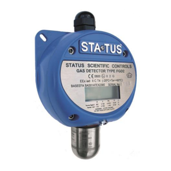
Page 25: Certification
STATUS SCIENTIFIC CONTROLS FGD2 & 3 Flammable Gas Detector Heads ERTIFICATION The FGD Flammable gas detectors carry the following markings: STATUS SCIENTIFIC CONTROLS GAS DETECTOR TYPE FGD3 1180 II 2 G Ex iad II C T4 Gb (-20°C<Ta<+60°C) BASEEFA BAS01ATEX2300 SERIAL No. -
Page 26: Mounting Details
STATUS SCIENTIFIC CONTROLS FGD2 & 3 Flammable Gas Detector Heads OUNTING ETAILS The diagram below shows the mounting centres for the FGD Detector Head Enclosure. Depth = 75mm approx Note: The front panel/lid of the detector head opens to allow access to the screw terminals situated inside.
Need help?
Do you have a question about the FGD2 and is the answer not in the manual?
Questions and answers