Table of Contents
Advertisement
Quick Links
Advertisement
Table of Contents

Related Manuals for Automaxx 400 Watt Turbine


Summary of Contents for Automaxx 400 Watt Turbine
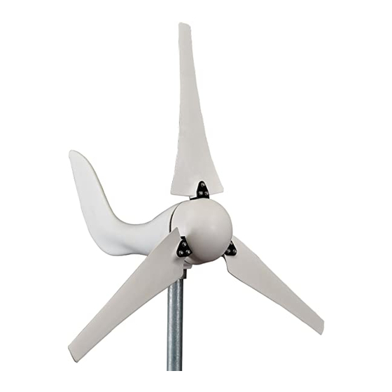
- Page 1 400 WATT WIND TURBINE User’s Manual Ver.2017.2.24...
-
Page 2: Table Of Contents
Table of Content 1. SAFETY ......................1 1.1 Mechanical Hazard ..................2 1.2 Electrical Hazard ..................2 2. SPECIFICATION AND PROTECTION ........... 2 2.1 Specifi cation ....................3 2.2 Performance ....................4 2.3 System Protection ..................5 2.4 Mechanical Stop Switch ................6 3. -
Page 3: Safety
1. SAFETY Your wind turbine is designed with your personal safety as the first priority. However, there are still some inherent dangers involved with any electrical and/or mechanical equipment. Safety must be the primary concern as you plan the location, installation and operation of the turbine. -
Page 4: Mechanical Hazard
1.1 Mechanical Hazard Rotating blades present the most serious mechanical hazard. The rotor blades are made of very strong thermoplastic. At the tip, the blades may be moving at velocities over 15 m/s. At this speed, the tip of a blade is nearly invisible and can cause serious injury. -
Page 5: Specification And Protection
The minimum recommended tower height is 30ft or 20ft above nearby obstructions as shown below. 20 feet (6m) 2. SPECIFICATION AND PROTECTION 2.1 Specifi cation Model 400 Watt Turbine Rated speed 28 mph / 12.5 m/s Rated power 400 watts *Output Voltage... -
Page 6: Performance
*The 400W wind turbine operates on 0-15V output voltage, we highly recommend using 12 AWG wire and maintaining a distance of 66ft (20m) between the turbine and battery. Using inappropriate wire gauge will result in a drastic increase in voltage. **Please activate the brake manually when the wind speed exceeds 30 mph (13 m/s). -
Page 7: System Protection
2.3 System Protection Your turbine comes equipped with state of the art overcharge protection. When the temperature of the turbine exceeds 80°C (176°F) your turbine will automatically shut down and apply the braking system to your wind turbine to prevent damage. High battery voltage protection 14.8V Over charging current protection... -
Page 8: Mechanical Stop Switch
2.4 Mechanical Stop Switch The wind turbine has built-in controller with braking device protection. Further to this protection we have incorporated a secondary level of safety and convenience with a mechanical 3-phase AC brake. During periods of high winds (upwards of 30 mph, 13 m/s) it is strongly advised to utilize your mechanical stop switch. - Page 9 S h o u l d t h e t u r b i n e c o n t i n u e t o s p i n , c h e c k y o u r t e r m i n a l connections.
-
Page 10: Package Contents
3. PACKAGE CONTENTS Check the parts listed with the contents of the box and make sure that you have everything needed for assembly. Blade Generator Tail Nose Cone Base Caution: The edges of the blades are sharp. Please handle with care. 3.1 Parts List Name Quantity... -
Page 11: System Wiring Diagrams
3.2 System Wiring Diagrams Please refer to the recommended wire gauge table and select the appropriate wire size for your system. -
Page 12: Installation Procedure
4. INSTALLATION PROCEDURE Step 1 : Open box and ensure all parts are present. Step 2 : Install the wind turbine to your chosen tower and fasten the bolt securely by using the hex key (The Yaw Shaft includes a rubber spacer to ensure the connection is secure). - Page 13 Step 3 : Fasten the blades on the hub with nuts by using the hex key and unilateral open wrench. (Make sure that all of the bolts are secured with nuts.)
- Page 14 Step 4 : Fit the nose cone onto the hub properly. Step 5 : Final product diagram...
-
Page 15: Maintenance
5. MAINTENANCE Your wind turbine has been designed to run for long periods without requiring any maintenance. Performance will be enhanced if you periodically inspect your system. Review the following simple maintenance procedures and implement every six months. Caution 1 : Do not go near the wind turbine during operation. Caution 2 : The blades are sharp. -
Page 16: Faqs
6. FAQS (1) How does the wind turbine control power and RPM in high winds? Your Turbine’s operation will be halted to reduce the risk of damage due to overcharge and over spin of the rotor blades. This process of braking is handled internally through your Turbines electronics. - Page 17 (5) Will it hurt my wind turbine to short-circuit the output? No, the wind turbine is designed to be short-circuited as a normal shutdown procedure by a fuse. The function of the stop switch is to both disconnect the turbine from the batteries as well as short-circuit the output of the turbine.
- Page 18 12V VOLT BATTERIES IN PARALLEL (9) Is lightning protection necessary? You should ground your wind turbine. Proper grounding (illustrated below) provides protection to individuals and equipment by eliminating the possibility of dangerous voltage. Remember a steel tower is a conduit for lightning.
-
Page 19: Troubleshooting
7. TROUBLESHOOTING You may require an extra person to assist with these tests. (1) Remove the blade/hub from the turbine. (2) Quickly spin the hub manually with your fi ngers while connecting and disconnecting the red and yellow wires (turbine must not be connected to batteries). -
Page 20: Warranty
8. WARRANTY We warrant your product to be free from defects in material and/or workmanship for a period of 1 year from original date of purchase. Warranty coverage is extended only to customer (original purchaser). If product proves defective during warranty period, the manufacturer, at its option will: 1. - Page 21 DISCLAIMER EXCEPT FOR THE EXPRESSED WARRANTY SET FORTH ABOVE, THE MANUFACTURER DISCLAIMS ALL OTHER EXPRESSED AND IMPLIED WARRANTIES, INCLUDING THE IMPLIED WARRANTIES OR FITNESS FOR A PARTICULAR PURPOSE, MERCHANTABILITY AND NON-INFRINGEMENT. NO OTHER WARRANTY, EXPRESSED OR IMPLIED, WHETHER OR NOT SIMILAR IN NATURE TO ANY OTHER WARRANTY PROVIDED HEREIN, SHALL EXIST WITH RESPECT TO THE PRODUCT SOLD UNDER THE PROVISIONS OF THESE TERMS AND CONDITIONS.
- Page 22 All notifi cations must include the following information: a) Description of alleged defect b) How the wind turbine was being used c) Serial # d) The original purchase date e) Name, phone #, address of party requesting warranty Within 2 to 3 business days the manufacturer will provide the customer with an RA# and will direct customer to location where the product is to be returned.
-
Page 23: Appendix A Important Safety Instructions
APPENDIX A IMPORTANT SAFETY INSTRUCTIONS Read these instructions below before installing your wind turbine to ensure people and property against accidents. Please also make sure it is set up under environmental and operating conditions. 1. Locate your wind turbine in windy sites so as not to disturb neighbors and animals around. - Page 24 Operating Environment: A. Operating Temperature: -4°F (-20°C) ~ 122°F (50°C) B. Operating Humidity: < 80% C. Average Wind Speed: < 34MPH (<15 m/s or <54KMH) D. Max. Peak Wind Speed: < 45MPH (<20m/s or <70KMH) E. Elevation: < 1000m F. Applicable Installation Height: 8.85ft ~ 33ft (2.7m ~ 10m) It is subject to IEC 61400-2 safety standards.
-
Page 25: Appendix B Beaufort Wind Scale
APPENDIX B BEAUFORT WIND SCALE Avg. Wind Avg. Wind Beaufort Description Avg. Wind Avg. Wind image Speed (m/s) Speed (mi/h) Calm Speed (knot/h) Speed (km/h) Clam <1 <2 <0.55 < 1.24 Light air 1 – 3 2 - 6 0.55~1.66 1.24~3.73 Light breeze 4 –... -
Page 26: Appendix C Recommended Wire Gauge
APPENDIX C RECOMMENDED WIRE GAUGE To determine the wire size, measure the distance from your turbine to the battery. Be sure to include height of the tower. A. Distance : AWG / Metric Wire Size System Voltage 14 / 2 mm B. -
Page 27: Appendix D Registration Form
APPENDIX D REGISTRATION FORM Registration Form RA No.:____________________ Serial No.: Date: Event Date: Location: Please fi ll out the following questions for further investigation. 1. The wire used between the wind turbine and the battery: ___________ AWG or metric wire size _______mm2 2.
Need help?
Do you have a question about the 400 Watt Turbine and is the answer not in the manual?
Questions and answers