BBH SMX Series Installation Manual
Hide thumbs
Also See for SMX Series:
- Installation manual (264 pages) ,
- Installation manual (60 pages) ,
- Installation manual (67 pages)

Related Manuals for BBH SMX Series


Summary of Contents for BBH SMX Series
- Page 1 Installation manual Installation Manual SMX series SMX Modular and SMX Modular, 2nd Generation (SMXGen2) HB-37420-810-01-25F-EN SMX100 Installation manual.docx Page 1 of 260 Version: 25F...
- Page 2 Installation manual Installation manual for base devices of SMX100 series - SMX100-1(/4x, /5x) - SMX100-2(/4x, /5x) - SMX100-4(/4x, /5x) and the expansion modules - SMX131 - SMX131R - SMX111 - SMX111-2 - SMX112 - SMX112A - SMX112-2 - SMX112-2A - SMX121 - SMX121-2 - SMX122 - SMX122A...
- Page 3 However, we would like to point out, that this document cannot always be updated at the same time as the technical further development of the products. Information and specifications can be changed at any time. Please keep yourself informed about the current version under www.bbh-products.de. Devices of the BBH Products GmbH Böttgerstraße 40...
-
Page 4: Table Of Contents
Installation manual Inhalt IMPORTANT NOTES .....................8 Definitions .............................. 8 Co-valid documents ..........................9 Abbreviations used ..........................11 SAFETY REGULATIONS ..................13 Intended use ............................13 Use in regions with UL/CSA requirements .................... 13 General safety regulations ........................14 Operation and service........................... 15 Transport/storage .......................... - Page 5 Installation manual Safety related characteristic data and wiring of the outputs .............. 101 4.3.1 Characteristic of the output elements ................101 4.3.2 Diagnoses in the cut-off circuit ..................102 4.3.2.1 Diagnostic Functions ....................102 4.3.2.2 Overview DC with respect to the chosen diagnostics functions ........103 4.3.3 Permissible capacitive and inductive load at safe outputs ..........
- Page 6 Installation manual 5.11.3 Connection variants ....................... 194 5.11.3.1 Connection of absolute encoders as master ............194 5.11.3.2 Connection of an absolute encoder as slave ............195 5.11.3.3 Connecting an incremental encoder with TTL-signal level ........196 5.11.3.4 Connection of a SIN/COS encoder ................. 197 5.11.3.5 Connection of a resolver as master ................
- Page 7 Installation manual 12.3.7 Verification software(program) and parameters .............. 249 12.3.7.1 Checking FUP ......................249 12.3.7.2 Validation of FUP against AWL and parameters by means of validation report..251 12.3.8 Performance of the system test / FIT (fault injection test) ..........253 APPENDIX ........................
-
Page 8: Important Notes
Installation manual 1 Important notes Definition of individual target groups Project engineers for safe drive systems: Engineers and technicians Assembly, electric installation, maintenance and replacement of devices: Maintenance electricians and service technicians Commissioning, operation and configuration: Technicians and engineers 1.1 Definitions The designation SMX100 is used as generic term for all derivatives from the SMX100 product range. -
Page 9: Co-Valid Documents
Installation manual 1.2 Co-valid documents Description Referenz Configuration of the SMX100 module SafePLC programming manual for stand-alone applications without (System CD) field-bus interfacing with the program "SafePLC" Validation report for implemented Safety inspection with acceptance parameterization and PLC-program protocol Acceptance test for general safety Certificate for type approval test as related applications safety control acc. - Page 10 Installation manual Options: - Standard field bus - Standard field bus and safety protocol - Universal communication interface - Decentral expansion module - Secure, analog inputs - Relays Specification see “Optional universal communication interface” Note: • Thoroughly read the manuals before you start the installation and the commissioning of the SMX module.
-
Page 11: Abbreviations Used
Installation manual 1.3 Abbreviations used Abbreviation Meaning Alternating voltage Instruction list ELIA Employer's liability insurance association Clock (cycle) Central Processing Unit Direct voltage Ix.y Digital Input (Digitaler Eingang) Deutsches Institut für Normung (German Institute for Standardization) Qx.y Digital Output (Digitaler Ausgang) Emergency Monitoring Unit oder External Monitoring Unit External Device Monitoring Electromagnetic compatibility... - Page 12 Installation manual Abbreviation Meaning SMMC Safe Master-Master Communication Synchronous Serial Interface T1, T2 Test pulse Output (test pulse output) Verband der Elektrotechnik, Elektronik und Informationstechnik e. (association for electrical engineering, electronics and information technology) Yx.y Auxiliary Output G.P. General purpose (Gerneral use) x = 0 …..
-
Page 13: Safety Regulations
See appendix "EC Declaration of Conformity" 2.2 Use in regions with UL/CSA requirements In case of modules of SMX series, which do not have UL/CSA approval, these modules can be used in USA and Canada under the following conditions: the switching voltage of the output relays must be limited to max. 24 V. -
Page 14: General Safety Regulations
Installation manual 2.3 General safety regulations Safety note: • In order to avoid damage to persons and property only qualified personnel is entitled to work on the device. The term qualified personnel refers to persons who have successfully completed electrotechnical training and are fully familiar with the applicable rules and standards of electrical engineering. -
Page 15: Operation And Service
Using our devices contrary to the rules and conditions specified hereunder can lead to injuries or fatalities as well as damage to connected devices and machines! This will also cause the loss of all warranty and compensation claims against BBH. 2.4 Operation and service The module must always be de-energized before installation and removal, or before disconnecting signal lines. -
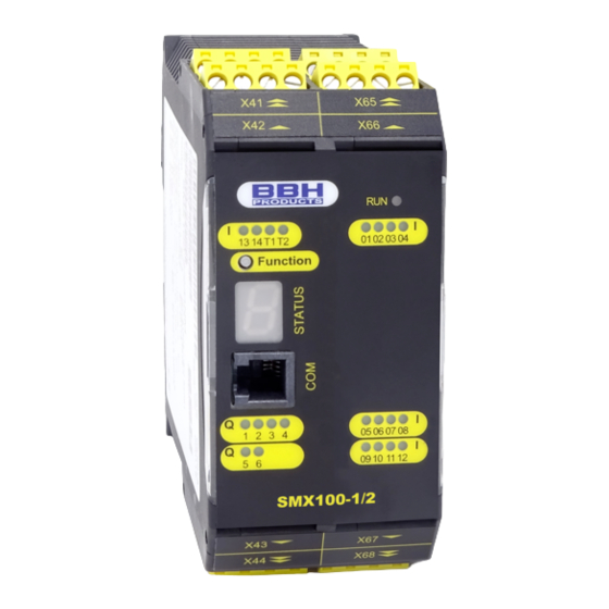
Page 16: Device Types
Installation manual 3 Device types The series SMX100 consists of base devices SMX100-x(/2) optionally with o integrated communication modules ▪ Standard field bus SMX100-x(/5x, /2/x ) or ▪ Safe field bus SMX100-x(/4x, /2/x central I/O expansion modules SMX131(/2), 131R(/2) and 131R-4/2 decentralised I/O expansion modules SMX132-x/2/D and 132-xR/2/D central axis expansion modules SMX121(/2), 121-2(/2), 122(/2) or 122A(/2) and 122- 2(/2) or 122-2A(/2) - Page 17 Installation manual Release version of the aforementioned device types The distinguishing of the device types takes place through the SMXGen2 characterization e.g.: SMX100-1/2) The following characteristics distinguish the two versions: Switchable outputs on the base devices; See technical data. Higher nominal loads of the outputs on the base devices. See technical data. Higher nominal loads of the outputs on the I/O expansion modules See technical data.
-
Page 18: Module Overview
Installation manual 3.1 Module overview Basic units Extension units central Extension units decentralised Designation SMX132-0/2/D, SMX122/122A/ SMX132-1/2/D, SMX112/112A/112- 100-1/100-2/100- SMX131/131R/31R-4(/2) 122-2/122-2A(/4x, 121/121-2(/4x, /x SMX132-0R/2/D, 111/111-2(/x , /D) 2/112-2A(/x , /D) (/4x, /x SMX132-1R/2/D General data Max. no. of expansion modules Safe digital inputs Safe digital I/Os -/20/40... - Page 19 Installation manual Of which maximum of 6 axis modules Specification; see: "Optional universal communication interface" HB-37420-810-01-25F-EN SMX100 Installation manual.docx Page 19 of 260 Version: 25F...
-
Page 20: Characteristic Data Of Device
Installation manual 3.2 Characteristic data of device 3.2.1 Basic modules 3.2.1.1 System module SMX100-1(/2, /4x, /5x, /x Type designation Device design Design of module with the following periphery: Digital inputs Pulse outputs Relay outputs pn- or pp- switching outputs Auxiliary outputs diagnostic- and configuration interface function button... - Page 21 Installation manual • Coded status display via front-side 7 segment display and status LEDs • Multifunction buttons (quit, start, reset) can be operated from the front side • Optional: Communication interface (/4x, /5x, /x o Standard and safe field bus protocols for communication with a higher level controller o Safe cross communication for data exchange between multiple base devices o Safe remote I/O communication for data exchange with distributed I/O systems...
- Page 22 Installation manual Technical characteristic data SMX100-1(/2, /4x, /5x, /x Safety related characteristic data Pl acc. to EN ISO 13849-1 PL e PFH / architecture 8,0 FIT /Cat 4 SIL acc. to IEC 61508 SIL 3 Proof test interval 20 years = max. operating period General data Max.
- Page 23 Installation manual -25C° … +70C° storage and transport Class of protection IP 20 Climatic category 3k3 acc. to DIN 60 721-3 Min-, Maximum relative humidity 5% - 85% (no condensation) EN 61000-6-2, EN 61000-6-4, EN 61000-6-7, EN 61800-3, EN 61326-3, EN 62061 Operating altitude 2000m Overvoltage category...
-
Page 24: System Module Smx100-2(/2, /4X, /5X, /X )
Installation manual 3.2.1.2 System module SMX100–2(/2, /4x, /5x, /x Type designation Device design Design of module with the following periphery: Digital inputs Pulse outputs Digital I/O‘s Relay outputs pn- or pp- switching outputs Auxiliary outputs Diagnostic and configuration interface Function button 7-segment display status LED status LEDs for inputs... - Page 25 Installation manual o Standard and safe field bus protocols for communication with a higher level controller o Safe cross communication for data exchange between multiple base devices o Safe remote I/O communication for data exchange with distributed I/O systems See: Chapter 3.2.4.3 Communication interface •...
- Page 26 Installation manual Technical characteristic data SMX100-2(/2, /4x, /5x, /x Safety related characteristic data Pl acc. to EN ISO 13849-1 PL e PFH / architecture 12,2 FIT /Cat 4 SIL acc. to IEC 61508 SIL 3 Proof test interval 20 years = max. operating period General data Max.
- Page 27 Installation manual Auxiliary outputs 24 VDC; 250mA (G.P.) 01 – 05 Digital I/O 24 VDC; 0,5A (G.P.) 10 – 15 06 – 10 Temperature rating 24 VDC; 2A (G.P.) 16 – 20 30°C Temperature rating 24 VDC; 1,8A (G.P.) 50°C Max.
- Page 28 Installation manual 3.2.1.3 System module SMX100–4(/2, /4x, /5x, /x Type designation Device design Design of module with the following periphery: Digital inputs Pulse outputs Digital I/O‘s Relay outputs pn- or pp- switching outputs Auxiliary outputs Diagnostic and configuration interface Function button 7-segment display status LED status LEDs for inputs...
- Page 29 Installation manual o Standard and safe field bus protocols for communication with a higher level controller o Safe cross communication for data exchange between multiple base devices o Safe remote I/O communication for data exchange with distributed I/O systems See: Chapter 3.2.4.3 Communication interface •...
- Page 30 Installation manual Technical characteristic data SMX100-4(/2, /4x, /5x, /x Safety related characteristic data Pl acc. to EN ISO 13849-1 PL e PFH / architecture 16,6 FIT /Cat 4 SIL acc. to IEC 61508 SIL 3 Proof test interval 20 years = max. operation period General data Max.
- Page 31 Installation manual Temperature rating 24 VDC; 1,8A (G.P.) 50°C pp-switching Temperature rating 24 VDC; 2A (G.P.) 30°C Temperature rating 24 VDC; 1,8A (G.P.) 50°C Max. total current (pn or pp) Auxiliary outputs 24 VDC; 250mA (G.P.) 01 – 05 Digital I/O 11 –...
-
Page 32: System Module Smx100-4
Installation manual 3.2.2 Central expansion modules 3.2.2.1 Expansion module SMX121(/2) Type designation Device design Design of module with the following periphery: Axis Encoder interfaces (*) Digital inputs status LED status LEDs for inputs Characteristics of the module: • Movement monitoring of one or two axes up to Pl e EN ISO 13849-1 or SIL 3 acc. to IEC 61508 •... - Page 33 Installation manual Technical characteristic data SMX121(/2) Safety related characteristic data Pl acc. to EN ISO 13849-1 PL e 3,0 FIT / Cat 4 / architecture SIL acc. to IEC 61508 SIL 3 Proof test interval 20 years = max. operation period General data Max.
-
Page 34: Expansion Module Smx121-2(/2)
Installation manual 3.2.2.2 Expansion module SMX121-2(/2) Type designation Device design Design of module with the following periphery: Expanded axis Encoder interfaces (*) Digital inputs status LED status LEDs for inputs Characteristics of the module: • Movement monitoring of one or two axes up to Pl e EN ISO 13849-1 or SIL 3 acc. to IEC 61508 •... - Page 35 Installation manual Technical characteristic data SMX121-2(/2) Safety related characteristic data Pl acc. to EN ISO 13849-1 PL e 3,0 FIT / Cat 4 / architecture SIL acc. to IEC 61508 SIL 3 Proof test interval 20 years = max. utilization period General data Max.
-
Page 36: Expansion Module Smx122/122A(/2)
Installation manual 3.2.2.3 Expansion module SMX122/122A(/2) Type designation Device design Design of module with the following periphery: Axes Encoder interfaces (*) Digital inputs Analogue inputs (Variant A) status LED status LEDs for inputs Characteristics of the module: • Movement monitoring of one or two axes up to Pl e EN ISO 13849-1 or SIL 3 acc. to IEC 61508 •... - Page 37 Installation manual Technical characteristic data SMX122/122A(/2) Safety related characteristic data Pl acc. to EN ISO 13849-1 PL e 3,0 FIT / Cat 4 / architecture 6,5 FIT / Cat 4 SIL acc. to IEC 61508 SIL 3 Proof test interval 20 years = max.
-
Page 38: Expansion Module Smx122-2/122-2A(/2)
Installation manual 3.2.2.4 Expansion module SMX122-2/122-2A(/2) Type designation Device design Design of module with the following periphery: expanded axes Encoder interfaces (*) Digital inputs Analogue inputs (Variant A) status-LED status LEDs for inputs Characteristics of the module • Movement monitoring of one or two axes up to Pl e EN ISO 13849-1 or SIL 3 acc. to IEC 61508 •... - Page 39 Installation manual Technical characteristic data SMX122–2/122-2A(/2) Safety related characteristic data Pl acc. to EN ISO 13849-1 PL e 6,5 FIT / Cat 4 / architecture SIL acc. to IEC 61508 SIL 3 Proof test interval 20 years = max. operation period General data Max.
-
Page 40: Expansion Module Smx131(/2), 131R(/2) And 131R-4/2
Installation manual 3.2.2.5 Expansion module SMX131(/2), 131R(/2) and 131R-4/2 Type designation Device design Design of module with the following periphery: Digital inputs Digitale I/O’s 10/2/6 Pulse outputs Auxiliary outputs 0/8/4 Relay outputs (Variante R) status-LED status LEDs for inputs status-LEDs for pulse outputs status-LEDs for I/O‘s Characteristics of the module: •... - Page 41 Installation manual Technical characteristic data SMX131(/2), 131R(/2) und 131R-4/2 Safety related characteristic data Pl acc. to EN ISO 13849-1 PL e PFH / architecture 9,2 FIT /Cat 4 plus in SMX31R/31R-4 1-channel per Rel 20 FIT max. 8) 2-channel per Rel 1,0 FIT max.
- Page 42 Installation manual -25C° … +70C° storage and transport Class of protection IP 20 Climatic category 3k3 acc. to DIN 60 721-3 Min-, Maximum relative humidity 5% - 85% (no condensation) EN 61000-6-2, EN 61000-6-4, EN 61000-6-7, EN 61800-3, EN 61326-3, EN 62061 Operating altitude 2000m Overvoltage category...
-
Page 43: Decentralised Expansion Modules
Installation manual 3.2.3 Decentralised expansion modules 3.2.3.1 Decentralised expansion module SMX111(/2/D) Type designation Device design Design of module with the following periphery: Axis Encoder interfaces (*) Digital inputs Pulse outputs Relay outputs pn- or pp- switching outputs Auxiliary outputs Diagnostic and configuration interface Function button 7-segment display... - Page 44 Installation manual • Assembly on top hat rail • The mechanical structure of SMX111/2/D differs from the figure. (See mechanical data) HB-37420-810-01-25F-EN SMX100 Installation manual.docx Page 44 of 260 Version: 25F...
- Page 45 Installation manual Technical characteristic data SMX111(/2/D) Safety related characteristic data Pl acc. to EN ISO 13849-1 PL e 12,6 FIT /Cat 4 / Architecture SIL acc. to IEC 61508 SIL 3 Proof test interval 20 years = max. operation period General data Max.
- Page 46 Installation manual EN 61000-6-2, EN 61000-6-4, EN 61000-6-7, EN 61800-3, EN 61326-3, EN 62061 Operating altitude 2000m Overvoltage category Degree of pollution Mechanical data Dimensions SMX111 = 100x115x45 (HxDxW [mm]) SMX111/2/D = 100x115x67,5 Weight SMX111 = 310 SMX111/2/D = 410 Mounting To snap on top-hat rail Number of T-bus connectors...
-
Page 47: Decentralised Expansion Module Smx111-2(/2/D)
Installation manual 3.2.3.2 Decentralised expansion module SMX111-2(/2/D) Type designation Device design Design of module with the following periphery: Expanded axis Encoder interfaces (*) Digital inputs Pulse outputs Relay outputs pn- or pp- switching outputs Auxiliary outputs Diagnostic and configuration interface Function button 7-segment display status LED... - Page 48 Installation manual o allows the connection of 2 rotary encoders per axis (SSI, Sin/Cos, TTL, Proxi) o 2nd encoder interface also supports HTL (200 kHz), Sin/Cos High-Resolution and Resolver • The mechanical structure of SMX111-2(/2/D) differs from the figure. (see: mechanical data) HB-37420-810-01-25F-EN SMX100 Installation manual.docx Page 48 of 260 Version: 25F...
- Page 49 Installation manual Technical characteristic data SMX111-2(/2/D) Safety related characteristic data Pl acc. to EN ISO 13849-1 PL e 12,6 FIT /Cat 4 / architecture SIL acc. to IEC 61508 SIL 3 Proof test interval 20 years = max. operation period General data Max.
- Page 50 Installation manual Climatic category 3k3 acc. to DIN 60 721-3 Min-, Maximum relative humidity 5% - 85% (no condensation) EN 61000-6-2, EN 61000-6-4, EN 61000-6-7, EN 61800-3, EN 61326-3, EN 62061 Operating altitude 2000m Overvoltage category Degree of pollution Mechanical data Dimensions SMX111-2 = 100x115x67,5...
-
Page 51: Decentralised Expansion Module Smx112/112A(/2/D)
Installation manual 3.2.3.3 Decentralised expansion module SMX112/112A(/2/D) Type designation Device design Design of module with the following periphery: Axes Encoder interfaces (*) Digital inputs Analogue inputs (Variant A) Pulse outputs Relay outputs pn- or pp- switching outputs Auxiliary outputs Diagnostic and configuration interface Function button 7-segment display status LED... - Page 52 Installation manual • The mechanical structure of SMX112/112A(/2/D) differs from the figure. (See mechanical data) HB-37420-810-01-25F-EN SMX100 Installation manual.docx Page 52 of 260 Version: 25F...
- Page 53 Installation manual Technical characteristic data SMX112/112A(/2/D) Safety related characteristic data Pl acc. to EN ISO 13849-1 PL e 12,6 FIT /Cat 4 / Architecture SIL acc. to IEC 61508 SIL 3 Proof test interval 20 years = max. operation period General data Max.
- Page 54 Installation manual Environmental data 0°C … +50°C operation Temperature -25C° … +70C° storage and transport Class of protection IP 20 Climatic category 3k3 acc. to DIN 60 721-3 Min-, Maximum relative humidity 5% - 85% (no condensation) EN 61000-6-2, EN 61000-6-4, EN 61000-6-7, EN 61800-3, EN 61326-3, EN 62061 Operating altitude 2000m...
-
Page 55: Decentralised Expansion Module Smx112-2/112-2A(/2/D)
Installation manual 3.2.3.4 Decentralised expansion module SMX112–2/112-2A(/2/D) Type designation Device design Design of module with the following periphery: expanded axes Encoder interfaces (*) Digital inputs Analogue inputs (Variant A) Pulse outputs Relay outputs pn- or pp- switching outputs Auxiliary outputs diagnostic and configuration interface Function button... - Page 56 Installation manual • Assembly on top hat rail • Extended functionality: o allows the connection of 2 rotary encoders per axis (SSI, Sin/Cos, TTL, Proxi) o 2nd encoder interface also supports HTL (200 kHz), Sin/Cos High-Resolution and Resolver • SMX112-2A(/2, /D) – Variant A (analogue) – 2 analogue inputs •...
- Page 57 Installation manual Technical characteristic data SMX112-2/112-2A(/2/D) Safety related characteristic data Pl acc. to EN ISO 13849-1 PL e 12,6 FIT /Cat 4 / architecture SIL acc. to IEC 61508 SIL 3 Proof test interval 20 years = max. operation period General data Max.
- Page 58 Installation manual -25C° … +70C° storage and transport Class of protection IP 20 Climatic category 3k3 acc. to DIN 60 721-3 Min-, Maximum relative humidity 5% - 85% (no condensation) EN 61000-6-2, EN 61000-6-4, EN 61000-6-7, EN 61800-3, EN 61326-3, EN 62061 Operating altitude 2000m Overvoltage category...
-
Page 59: Decentralised Expansion Module Smx132-0(R)/2/D / 132-1(R)/2/D
Installation manual 3.2.3.5 Decentralised expansion module SMX132-0(R)/2/D / 132-1(R)/2/D Type designation Device design Design of module with the following periphery: Digital inputs 0/10 Digital I/Os Pulse outputs Relay outputs pn- or pp- switching outputs Auxiliary outputs 7-segment display status-LED status LEDs for inputs status-LEDs for relay outputs status-LEDs für I/O‘s status-LEDs for outputs... - Page 60 Installation manual Technical characteristic data SMX132-0(R)/2/D / 132-1(R)/2/D Safety related characteristic data Pl acc. to EN ISO 13849-1 PL e 9,2 FIT /Cat 4 / Architecture Plus in SMX132-xR/2/D 1-kanalig pro Rel 20 FIT (max. 8) 2-kanalig pro Rel 1,0 FIT max.
- Page 61 Installation manual Max. total current (pn or pp) Auxilary outputs 24 VDC; 250mA (G.P.) 01 – 05 Digital I/O 24 VDC; 0,5A (G.P.) 06 – 10 Temperature rating 24 VDC; 2A (G.P.) 30°C Temperature rating 24 VDC; 1,8A (G.P.) 50°C Max.
-
Page 62: Communication Interface
Installation manual 3.2.4 Communication interface 3.2.4.1 SMX5x Type designation Device design Designs of the module with following peripherals: SMX51 CAN 2.0 SMX52 PROFIBUS SMX53 PROFINET SMX54 CANopen SMX55 EtherCAT SMX57 DeviceNet backplane bus interface status LED for operating status status LED CAN-communication Characteristics of the module: •... - Page 63 Installation manual Technical characteristic data: SMX5x Safety related characteristic data Pl acc. to EN ISO 13849-1 n.a. PFH / architecture n.a. SIL acc. to IEC 61508 n.a. Proof test interval n.a. General data Fieldbus interface Type of connection Standard acc. to field bus type Max.
-
Page 64: Smx4X
Installation manual 3.2.4.2 SMX4x Type designation Device design SMX43 Designs of the module with following peripherals: SMX45 SMX43 PROFIsafe over PROFINET SMX45 FSoE Fail Safe over EtherCAT status LED for operating status status LED internal SPI communication status LED field bus Characteristics of the module: •... - Page 65 Installation manual Technical characteristic data: SMX4x Safety related characteristic data Pl acc. to EN ISO 13849-1 n.a. PFH / architecture n.a. SIL acc. to IEC 61508 n.a. Proof test interval n.a. General data Fieldbus interface Type of connection Standard acc. to field bus type Max.
-
Page 66: Optional Universal Communication Interface
Storage medium for safety program Properties of the universal communication interface: • Optional specification of the SMX series communication interface • Subsequent expansion capability of standard to safe field bus via additional Mini SD card on the back side of the module is possible. (/xNx and /xBx) •... - Page 67 Installation manual Technical characteristic data: Optional universal communication interface Safety related characteristic data Pl acc. to EN ISO 13849-1 n.a. PFH / architecture n.a. SIL acc. to IEC 61508 n.a. Proof test interval n.a. General data Decentralised communication interfaces 2x RJ 45* Field bus interfaces 2x RJ 45** 1x Sub-D***...
-
Page 68: Encoder Specifications
Installation manual 3.2.4.4 Encoder specifications Physical Layer RS-422 compatible Measuring signal A/B Track with 90 degree phase difference Max. frequency of input cycles (X31, 250 kHz / 500 kHz X32 / X33, X34) Type of connection D-SUB 9pol Sin / Cos Physical Layer RS-422 compatible Measuring signal A/B... -
Page 69: Derating Outputs
Installation manual 3.3 Derating outputs Maximum current load based on temperature. This derating should be considered for all 2A outputs (IO-Board and REL-Board)! 2A outputs can be fully loaded at an ambient temperature of up to 30°C. From a ambient temperature from 30°C to maximum 50°C, the 2A outputs can be loaded to a maximum of 1.8A. -
Page 70: Type Plate Smxgen2 (/2)
Installation manual 3.4.2 Type plate SMXGen2 (/2) The type plate is located on the left side wall of the module and contains the following information: Type designation Part number Serial number Identification of hardware release Identification of software release Safety category Input characteristics Output characteristics Date of manufacture (week/year) -
Page 71: Scope Of Delivery
Installation manual 3.4.3 Scope of delivery The scope of delivery contains: SMX module: • Plug for all signal terminals without encoder connection Not included in the scope of delivery: • SafePLC configuration software CD with ➢ Installation manual ➢ Programming manual ➢... -
Page 72: Safety Related Characteristics
Installation manual 4 Safety related characteristics 4.1 General design, safety related architecture and characteristic data The inner structure of all modules of SMX100 series with the exception of communication interfaces consist of two separate channels with reciprocal comparison of results. High quality diagnoses for fault detection are made in each of the two channels. - Page 73 Installation manual The following cases should be differentiated: a) Axis module with safety functions related to an axis or use of safe inputs at an expansion module and shut-off channel via outputs of the base module SDDC Sensor Kommunikation Aktuator Erweiterungsbaugruppe Basisbaugruppe SMX100-System...
- Page 74 Installation manual d) Axis module with safety functions related to an axis or use of safe inputs at an expansion module and shut-off channel via outputs of an expansion module SDDC SDDC Kommunikation Kommunikation Aktuator Basisbaugruppe Erweiterungsbaugruppe Erweiterungsbaugruppe SMX100-System = PFHSMX + PFH + PFH + 2 * PFH...
- Page 75 Installation manual Characteristic data: • Max. obtainable safety class SIL 3 acc. to IEC 61508 • Category 4 acc. to EN ISO 13849-1 • Performance-Level e acc. to EN ISO 13849-1 System structure System structure 2-channel with diagnose /1002) acc. to EN 61508 Architecture category 4 acc.
-
Page 76: Safety Related Characteristic Data And Wiring For The Connected Sensors
Installation manual 4.2 Safety related characteristic data and wiring for the connected sensors The SMX modules have completely separated signal processing paths for each safety input. This applies for both the digital and the analog inputs. Furthermore, measures for achieving the highest possible DC-values have been implemented. -
Page 77: Dc Digital Sensors/Inputs
Installation manual 4.2.1.2 DC digital sensors/inputs The SMX100 modules ensure far reaching diagnostics functions for the input element. These are carried out permanently, or optionally (cross-shorting monitoring by means of pulse identifier, cross-comparison, 2- or multi-channel sensor with/without time-out, start-up test). Permanently active diagnostics functions: Cross-comparison: SMX module inputs are in general internally designed with two channels. - Page 78 Installation manual Start test: Each time the safety module (=SMX module) is switched on, the input element must be tested in direction of the Low signal status (defined Safe State), e.g. by actuating the Emergency Stop button or a door lock after the system has been started. Operational / organizational tests: Apart from the previously mentioned diagnostic measures for the SMX modules, cyclic testing can be performed within the application.
- Page 79 Installation manual The following diagnoses for input sensors can generally be used for the safety related assessment of the entire system: Input element Parameterized / Definition of measure Note characteristic operational tests Single-channel Cyclic test pulse by dynamic A sufficiently high >60 change of input signals test rate must be...
-
Page 80: Classification Of Digital Inputs
Installation manual Safety note: • The manufacturer's data (MTTFD, FIT-numbers, etc.) must be used for a safety related assessment of the partial system "Sensors". • The DC-values listed in the table must be used conservatively and compliance with the boundary conditions (see table under „Remarks“) must be ensured. •... - Page 81 Installation manual 4.2.1.3.2 Digital inputs I/O’s (IQIx) Digital inputs Achievable Comment performance level Without pulse, single channel static signal -> auxiliary input Without pulse, dual channel static signal At least one request/day required by PL e application Fault detection only upon request Without pulse, dual channel static signal PL d Less than one request/day required by...
-
Page 82: Exemplary Connections Of Digital Sensors
Installation manual 4.2.1.4 Exemplary connections of digital sensors 4.2.1.4.1 Single-channel sensor, without cross-shorting test Fig.: Single-channel sensor, without cross-shorting test The single-channel sensor is connected to the SMX100 without clocking or without cross- shorting test. This design is not recommended for safety applications. Pl b acc. to EN ISO 13849-1 can maximally be reached. - Page 83 Installation manual When using a single-channel sensor with clocking, the power supply of the switching element is attached to the clock exit T1 or T2. The clock must subsequently be assigned to the SMX100. The use of a single-channel sensor with clock detects: short-circuit to supply voltage DC 24 V short-circuit to DC 0 V cable interruption (current interruption is safe state!)
- Page 84 Installation manual 4.2.1.4.3 Dual-channel sensor without timeout with cross-shorting test Faults are at least detected when requested. The DC is medium and by using cyclic tests (start test, operational/organizational tests) can be changed up to high level. depending on the test frequency.
- Page 85 Installation manual Safety note: • Pl d or higher in accordance with EN ISO 13849-1 is achieved by using switching elements / sensors with positively opening contacts or positive actuation acc. to EN 60947-5-1 • Using devices for which the fault exclusion double fault for the intended safety level can be specified for the switching elements, is permitted.
- Page 86 Installation manual 4.2.1.4.4 Dual-channel sensor with time-out and cross-shorting test Cross-shorting as well as connections to DC 24 V and DC 0 V can be detected by using two independent clock signals on the homogeneous sensor. Pl d or higher acc. to EN ISO 13849-1 can be achieved when: - Use of sensors/switching elements with forced actuation.
-
Page 87: Overview Of Achievable Pi For Digital Safety Inputs
Installation manual 4.2.1.5 Overview of achievable PI for digital safety inputs Type of sensor / Input Parameterized / Achievable PI Fault exclusion for input Condition for input element input element operational tests acc. to element EN ISO 13849-1 Operation proven input element I01 ... - Page 88 Installation manual Type of sensor / InPort Parameterized / Achievable PI Fault exclusion for input Condition for input element input element operational tests acc. to EN element 13849-1 Short-circuit between input/signal line Connection in control cabinet or (only with common switching protected routing Dual-channel parallel elements = 2xNO or 2xNC)
-
Page 89: Sensors For Speed And/Or Position Detection
Installation manual 4.2.2 Sensors for speed and/or position detection 4.2.2.1 General safety related structure of the sensor interface for position and/or speed The expansion modules of the SMX100 series can be optionally equipped with one (SMX111, SMX112, SMX121, SMX122) or two encoder interfaces (SMX111-2, SMX112-2, SMX121-2, SMX122-2) per axis. -
Page 90: General Diagnostic Measures For Encoder Interface
Installation manual 4.2.2.2 General diagnostic measures for encoder interface For fault detection in the sensor system the SMX series has a number of diagnostic measures implemented, depending on the chosen encoder type or its combination. These are automatically activated when choosing the encoder type. -
Page 91: Encoder Types And Their Combination, Diagnostic Data
Installation manual 4.2.2.3 Encoder types and their combination, diagnostic data 2-channel 2-channel partial Safe Safe Safe partial system Encoder A Encoder B absolute Fault exclusion 1-channel speed direction system non- position partial system dynamic dynamic (standstill monitoring) Fault exclusion mech. shaft breakage, positive encoder shaft connection 1 x Proxi 1 x Proxi... - Page 92 Installation manual 2-channel 2-channel partial Safe Safe Safe partial system Encoder A Encoder B absolute Fault exclusion 1-channel speed direction system non- position partial system dynamic dynamic (standstill monitoring) Resolver n.a. 95-99% n.a. 90-95% Fault exclusion mech. shaft breakage, SIN/COS positive encoder shaft connection 90-95% required...
-
Page 93: Specific Diagnostic Measures With Regard To The Encoder Type Used
Installation manual 4.2.2.4 Specific diagnostic measures with regard to the encoder type used Encoder type Incremental SIN/COS Proxi 2 x counting input Proxi 2 x counting input Incremental Resolver SIN/COS Only in High-Resolution Mode HB-37420-810-01-25F-EN SMX100 Installation manual.docx Page 93 of 260 Version: 25F... -
Page 94: Safety Relevant Cut-Off Thresholds Encoder Systems For Position And Speed Detection
Installation manual 4.2.2.5 Safety relevant cut-off thresholds encoder systems for position and speed detection Plausibility tests with the current position and speed values are performed between both measuring channels A and B of the SMX100 module as a basic measure, which are then checked against parameterizable thresholds. - Page 95 Installation manual Value Wert Acceleration [rev/min/s] Resolution Graph acceleration, rotary Graph acceleration, linear (Values in rev/min/s) (Values in mm/s and m/s²) Acceleration [mm/s ] und [m/s ² ² Safety note: • The fault can be optimized by choosing a suitable sensor resolution for the corresponding application.
- Page 96 Installation manual • The filter time can be variably set between 0 and 64 in steps of 8. The dimension is "msec". In order to determine the response time of the overall system, the filter times must be added to the specified response times of the SMX systems (see chapter 11). Safety note: •...
-
Page 97: Safety Related Assessment Of Encoder Types Or There Combination
Installation manual 4.2.2.6 Safety related assessment of encoder types or there combination Due to the monitoring functions implemented in the SMX-series, no special demands are initially made on the internal design of the encoder electronics in applications with encoder systems, i.e. standard encoders can normally be used. - Page 98 Installation manual The SMX100 module generally detects the following faults in the external encoder system: • Short-circuits between safety relevant signal lines • Interruptions in safety relevant signal lines • Stuck at 0 or 1 on one or all safety relevant signal lines Each encoder type has further specific diagnoses for fault detection in the external encoder system assigned.
-
Page 99: Analog Sensors
Installation manual 4.2.3 Analog sensors The basic modules SMX12A have two analog inputs with two input channels each. Only 2-channel sensors can generally be connected to this interface. The internal signal processing takes place separately in the two channels with cross-comparison of the results. -
Page 100: Exemplary Connection Of Analog Sensors
Installation manual Safety note: • The manufacturer's data (MTTF , FIT-numbers, etc.) must be used for a safety related assessment of the partial system "Sensors". • The DC-values listed in the table must be used conservatively and compliance with the boundary conditions (see table under „Remarks“) must be ensured. -
Page 101: Safety Related Characteristic Data And Wiring Of The Outputs
Installation manual Safety related characteristic data and wiring of the outputs SMX modules all have safe outputs of various types. For wiring, the corresponding characteristic as specified in the following description, must be accounted for. 4.3.1 Characteristic of the output elements Actuator Aktuator Single-channel output SMX and single-channel actuator without diagnostics... -
Page 102: Diagnoses In The Cut-Off Circuit
Installation manual Aktuator Actuator Single-channel output SMX with internal dual-channel processing (IQQ x) and dual-channel actuator with dual-channel diagnose Aktuator Actuator Dual-channel output SMX and dual-channel actuator with single-channel diagnose Aktuator Actuator Dual-channel output SMX and dual-channel actuator with dual-channel diagnose 4.3.2 Diagnoses in the cut-off circuit The cut-off circuit is equipped with durably implemented and parametrizable diagnostics functions. -
Page 103: Overview Dc With Respect To The Chosen Diagnostics Functions
Installation manual Parametrizable diagnostics functions: Readback of the actuator status via auxiliary contacts, position indicators, etc.: The current status of the actuator is detected by correspondingly suitable auxiliary contacts or position indicators and compared with the nominal status. Any deviation is thereby clearly recognized. -
Page 104: Permissible Capacitive And Inductive Load At Safe Outputs
Installation manual 4.3.3 Permissible capacitive and inductive load at safe outputs The safe outputs of the SMX100 exhibit an OSSD character. That is, the outputs are cyclically switched off for the test of the switching off ability and the status is read back. The examination of the switching off ability takes place according to the following criteria/functions: After switching the output off, the output voltage may max. -
Page 105: Digital Outputs
Installation manual 4.3.4 Digital Outputs The modules • SMX100-1(/2), SMX100-2(/2), SMX100-4(/2) • SMX111(/2/D), SMX111-2(/2/D), SMX112(/2/D), SMX112-2(/2/D) • SMX131x(/2), SMX132-x(R)/2/D all have basic outputs of identical design. 4.3.4.1 Characteristic data of the basic outputs The SMX-Serie provides a total of 8 outputs, which can be interconnected individually or in groups. - Page 106 Installation manual Safety note: • For applications with frequent safety shut-down requests these tests should be performed more frequently, e.g. at the beginning of the shift, 1 x per week. However, a test should at least be carried out cyclically 1 x year. The test function for the outputs is performed for groupes and individual controls.
-
Page 107: Wiring Examples Basic Outputs
Installation manual o at a load resistance < 100 Ω with a holding capacity > 0.4 mW Only relevant with SMXGen2 (/2) to HW release 11-xx-xx… • For the output system a vast number of diagnostic measures have been implemented. Special attention must be paid to the inclusion of elements for switching amplification, such as relays, contactors, etc. - Page 108 Installation manual 4.3.4.2.2 Single-channel switching relay or semi-conductor output with external switching amplifier and testing When using external switching amplifiers or downstream electro-mechanical, pneumatic or hydraulic components, the setup for testing the complete chain and a message/warning feature for detected faults is required in order to achieve PI c or higher. Positively guided auxiliary contacts are especially needed for electro-mechanical devices and message contacts for the valve position are required for hydraulic or pneumatic components.
- Page 109 Installation manual 4.3.4.2.3 Single-channel switching relay or semi-conductor output with dual-channel external circuit with testing For safety applications from PL C after EN ISO 13849-1 it is recommended, or demanded to access two external switching off elements. For reaching error of PL c or higher, a device for testing the complete chain and a notification/warning device is further required when an error is recognized - for this see notes under 4.3.4.2 .2.
- Page 110 Installation manual Q1_PP Q2_PN Q3_PP Q4_PN Fig.: Single-channel switching output Q1_PP with dual-channel external circuit as combination of electro-mechanical element and hydraulic/pneumatic valve and monitoring at two inputs Safety note: • Only conditionally recommended for safety applications! In this context see also the notes in EN ISO 13849-1 concerning the application and the required fault exclusions.
- Page 111 Installation manual 4.3.4.2.4 Two-channel switching relay output with external monitoring - group feedback For safety related applications from Pl d acc. to EN ISO 13849-1 two relays on the SMX1xx module and two external power contactors are used. Q5.1 Q5.2 Q6.1 Q6.2 Two-channel switching relay output with external monitoring –...
- Page 112 Installation manual 4.3.4.2.5 Dual-channel output with relay output and semi-conductor output – external control circuit with monitoring For safety applications from PI d and higher acc. to EN ISO 13849-1. The external circuit is controlled in dual-channel mode via a relay and a semi-conductor output. Each of the two external cutout paths is monitored.
- Page 113 Installation manual 4.3.4.2.7 Dual-channel output with semi-conductor output and external control circuit in PI e For safety applications from PI d and higher acc. to EN ISO 13849-1. The external circuit is controlled in dual-channel mode via the semi-conductor outputs. For PL e acc. to EN ISO 13849-1 PI e is demanded for the external circuit Q1_PP Pl e...
-
Page 114: Digital Outputs I/O's (Iqqx)
Installation manual 4.3.5 Digital outputs I/O’s (IQQx) The modules SMX100-2(/2), SMX100-4(/2) SMX131(/2), SMX131R(/2), SMX131R-4/2 SMX132-x(R)/2/D respectively have configurable safe digital I/O's in different numbers (see chapter 3 module overview). This connection acts as safe digital pp-switching output parameterized as output (IQQx). -
Page 115: Wiring Examples For Safe Digital Outputs I/O's (Iqqx)
Installation manual 4.3.5.2 Wiring examples for safe digital outputs I/O's (IQQx) 4.3.5.2.1 Wiring single-channel without testing When using a two-channel output (IQQx) in connection with a single-channel external wiring without external examination it must be taken into account that and adherence of one or several external contacts of the SMX1xx module is not recognized. - Page 116 Installation manual 4.3.5.2.2 Wiring single-channel with testing When using a two-channel output (IQQx) in connection with a single-channel external wiring with testing. Positively guided auxiliary contacts are especially needed for electro-mechanical devices and message contacts for the valve position are required for hydraulic or pneumatic components. Furthermore, a message/warning device for indicating a failure is required.
- Page 117 Installation manual 4.3.5.2.3 Wiring with safe cut-off circuit For safety applications from PI c and higher acc. to EN ISO 13849-1. The external circuit is controlled directly via a two-channel output. The achievable PL acc. to EN ISO 13849-1 depends on the use of dynamic testing (see 4.3.2.1 DC) and the PL of the downstream device.
- Page 118 Installation manual 4.3.5.2.5 Redundant two-channel output Suitable for PI d and higher acc. to EN ISO 13849-1. Use of two outputs IQQx in connection with a dual-channel external wiring. 4.3.5.2.5.1 Outputs in the same group IQQ01 IQQ02 IQQ03 IQQ04 IQQ05 IQQ06 IQQ07 IQQ08...
- Page 119 Installation manual 4.3.5.2.5.2 Outputs in different groups IQQ01 IQQ02 IQQ03 IQQ04 IQQ05 IQQ06 IQQ07 IQQ08 IQQ09 IQQ10 Fig.: Redundant two-channel outputs in different groups in connection with two-channel switching-off circuit Safety note: • For a safety related assessment of the partial system output the data issued by the respective manufacturer (MTTF , FIT-numbers, B10d-value, etc.) must be used when using external elements, e.g.
-
Page 120: Overview Of Achievable Pi For Digital Safety Outputs
Installation manual 4.3.5.3 Overview of achievable PI for digital safety outputs Output SMX Actuator / Categor MTTF Achieva Boundary Fault external shut- y acc. to Actuat ble PI conditions exclusion down circuit EN13849 acc. to EN ISO 13849-1 Single-channel Single-channel Cat. - Page 121 Installation manual Output SMX Actuator / Categor MTTF Achieva Boundary Fault external shut- y acc. to Actuat ble PI conditions exclusion down circuit EN13849 acc. to 13849-1 Dual-channel Dual-channel Cat. 3 Monitoring Medium Contactor and Short circuit without Contactor, valve, in both or High downstream...
-
Page 122: Connection And Installation
Installation manual 5 Connection and installation 5.1 General notes on installation Strictly follow the safety regulations when installing! Degree of protection IP20 Route all signal lines for the interfacing of digital inputs and contact monitoring separately. You should in any case disconnect 230VAC (120VAC cULus) voltages from extra-low voltage lines (24V), if these voltages are used in connection with the application. - Page 123 Installation manual Symbol 14 • The temperature at the connecting terminals can amount to over 60°C. From this temperature, suitable cable types must be used. HB-37420-810-01-25F-EN SMX100 Installation manual.docx Page 123 of 260 Version: 25F...
-
Page 124: Installation And Assembly Of The Smx100 Module
In this case the backplane bus system needs to be configured by BBH when placing the order and delivered in accordance with the application in question. The backplane bus system consists of a 5-pin plug connector with snap-in contacts. In these plug connectors all 5 contacts are equipped by standard. -
Page 125: Arrangement Examples
Installation manual 5.3.1 Arrangement examples 5.3.1.1 SMX100-1 + SMX122 + SMX5x SMX5x SMX100-1 SMX122 There is no TB2 between the SMX122 module and the communication module SMX5x because the power supply for the SMX5x is fed in through the backplane bus system. 5.3.1.2 SMX100-2 + SMX121-2 + SMX5x SMX5x SMX100-2... -
Page 126: Assembling The Modules
Installation manual 5.4 Assembling the modules The modules are mounted on C-standard rails by means of snap-on latches. 5.4.1 Assembly on C-rail The devices are inserted into the rail under an oblique angle and then snapped on downwards. For disassembling use a screwdriver, insert it into the slot of the downwards pointing latch and then move it up. -
Page 127: Assembly On Backplane Bus
Installation manual 5.4.2 Assembly on backplane bus After assembling the backplane bus the device can be installed. For this purpose insert the module from above into the plug connection under a oblique angle and snap it onto the C-rail. Insert the module from above under an oblique angle. Snap-on downwards on to the C-rail. -
Page 128: Installation Und Konfiguration Von Master <-> Master (Smmc) Und Master <-> Slave (Sddc)
Installation manual Snap the backplane bus element into the C-rail and insert it into the counter-piece by sliding it sideways. 5.5 Installation und Konfiguration von Master <–> Master (SMMC) und Master <-> Slave (SDDC) The SMMC communication enables the safe data exchange of 2 byte between several SDDC masters. -
Page 129: Network Topology
Installation manual 5.5.1 Network topology SMMC SDDC CAN (Zentral) SDDC ETH (Dezentral) Communication of a SMX compact with • central expansion modules via SDDC CAN rear wall bu • SMMC via Ethernet Communication of a SMX modular with • central expansion modules via SDDC CAN rear wall bus •... -
Page 130: Installation I/O-Extension
Installation manual 5.5.2 Installation I/O-extension Note: Max. 8 SMX 1xx modules can be operated with one basic unit. 5.5.2.1 Physical address configuration of the slave modules (central/decentral) On the SMX1xx module the bus address must be set with the help of the address switch. This setting is made on the back of the module Note: •... -
Page 131: Terminal Assignment
Installation manual 5.6 Terminal assignment 5.6.1 Terminal assignment SMX100-1(/2) SMX100-1 SMX100-1/2 (SMXGen2 (/2): the PSU is omitted) Terminal assignment Unit Terminal Description Note SMXGen2 (/2) 1 - U24_EXT 1 - A1.1 Voltage supply device +24 VDC from SMXGen2 2 - U24_EXT 2 - A1.2 Voltage supply device +24 VDC Outputs (/2) - Page 132 Installation manual Terminal assignment Unit Terminal Description Note SMXGen2 (/2) 1 - U24_EXT1 Voltage supply device +24 VDC 2 - U24_EXT2 Voltage supply device +24 VDC 3 - GND_EXT1 Voltage supply device 0 VDC 4 - GND_EXT2 1 – NC 2 –...
-
Page 133: Terminal Assignment Smx100-2(/2)
Installation manual 5.6.2 Terminal assignment SMX100-2(/2) SMX100-2 SMX100-2/2 (SMXGen2 (/2): the PSU is omitted) HB-37420-810-01-25F-EN SMX100 Installation manual.docx Page 133 of 260 Version: 25F... - Page 134 Installation manual Terminal assignment Unit Terminal Description Note SMXGen2 (/2) 1 - U24_EXT 1 - A1.1 Voltage supply device +24 VDC 2 - U24_EXT 2 - A1.2 Voltage supply device +24 VDC Outputs 3 - GND_EXT 3 - A2.1 Voltage supply device 0 VDC 4 - GND_EXT 4 - A2.2 1 - DI13...
- Page 135 Installation manual Terminal assignment Unit Terminal Description Note SMXGen2 (/2) 1 - U24_EXT 1 - A1.5 Voltage supply device +24 VDC Outputs 2 - U24_EXT 2 - A1.6 3 - GND_EX3 3 - A2.5 Voltage supply device 0 VDC 4 - GND_EXT 4 - A2.6 1 - IO11 1 - IQ11...
- Page 136 Installation manual Terminal assignment Unit Terminal Description Note Release /2 1 - NC 1 - NC No function 2 - NC 2 - NC 3 - DO0.1 3 - Y1 Auxiliary outputs 4 - DO0.2 4 - Y2 1 - DI1 1 - I01 2 - DI2 2 - I02...
-
Page 137: Terminal Assignment Smx100-4(/2)
Installation manual 5.6.3 Terminal assignment SMX100-4(/2) SMX100-4 SMX100-4/2 (SMXGen2 (/2): the PSU is omitted) HB-37420-810-01-25F-EN SMX100 Installation manual.docx Page 137 of 260 Version: 25F... - Page 138 Installation manual Terminal assignment Unit Terminal Description Note SMXGen2 (/2) 1 - U24_EXT 1 - A1.1 Voltage supply device +24 VDC 2 - U24_EXT 2 - A1.2 Voltage supply device +24 VDC Outputs 3 - GND_EXT 3 - A2.1 Voltage supply device 0 VDC 4 - GND_EXT 4 - A2.2 1 - DI13...
- Page 139 Installation manual Terminal assignment Unit Terminal Description Note SMXGen2 (/2) 1 - U24_EXT 1 - A1.5 Voltage supply device +24 VDC Outputs 2 - U24_EXT 2 - A1.6 3 - GND_EXT 3 - A2.5 Voltage supply device 0 VDC 4 - GND_EXT 4 - A2.6 1 - IO11 1 - IQ11...
- Page 140 Installation manual Terminal assignment Unit Terminal Description Note SMXGen2 (/2) 1 - U24_EXT 1 - A1.9 Voltage supply device +24 VDC Outputs 2 - U24_EXT 2 - A1.10 3 - GND_EXT 3 - A2.9 Voltage supply device 0 VDC 4 - GND_EXT 4 - A2.10 1 - IO31 1 - IQ31...
- Page 141 Installation manual Terminal assignment Unit Terminal Description Note SMXGen2 (/2) 1 - NC 1 - NC No function 2 - NC 2 - NC 3 - DO0.1 3 - Y1 Auxiliary outputs 4 - DO0.2 4 - Y2 1 - DI1 1 - I01 2 - DI2 2 - I02...
-
Page 142: Terminal Assignment Smx121(/2)
Installation manual 5.6.4 Terminal assignment SMX121(/2) SMX121 SMX121/2 (SMXGen2) CPU-ENC CPU-ENC Terminal assignment Unit Terminal Description Note SMXGen2 (/2) 1 – U_ENC_2 1 – UE1+ Voltage supply encoder +24V DC X31 2 – GND_ENC_2 2 – UE1- Voltage supply encoder 0V DC X31 3 –... -
Page 143: Terminal Assignment Smx121-2(/2)
Installation manual 5.6.5 Terminal assignment SMX121-2(/2) SMX121-2 SMX121-2/2 (SMXGen2) CPU-ENC EXT-ENC CPU-ENC EXT-ENC Terminal assignment Unit Terminal Description Note SMXGen2 (/2) 1 – U_ENC_1 1 – UE1+ Voltage supply encoder +24V DC X31 2 – GND_ENC_1 2 – UE1- Voltage supply encoder 0V DC X31 3 –... - Page 144 Installation manual Terminal assignment Unit Terminal Description Note SMXGen2 (/2) 1 – U_ENC_3 1 – UE3+ Voltage supply encoder +24V DC X33 2 – GND_ENC_3 2 – UE3- Voltage supply encoder 0V DC X33 3 – U_REF_3 3 – UR3 Reference voltage encoder X33 4 –...
-
Page 145: Terminal Assignment Smx122(/2)
Installation manual 5.6.6 Terminal assignment SMX122(/2) SMX122 SMX122/2 (SMXGen2) CPU-ENC CPU-ENC Terminal assignment Unit Terminal Description Note SMXGen2 (/2) 1 – U_ENC_1 1 – UE1+ Voltage supply encoder +24V DC X31 2 – GND_ENC_1 2 – UE1- Voltage supply encoder 0V DC X31 3 –... - Page 146 Installation manual Terminal assignment Unit Terminal Description Note SMXGen2 (/2) 1 – U_ENC_2 1 – UE2+ Voltage supply encoder +24V DC X32 2 – GND_ENC_2 2 – UE2- Voltage supply encoder 0V DC X32 3 – NC 3 – NC No function 4 –...
-
Page 147: Terminal Assignment Smx122A(/2)
Installation manual 5.6.7 Terminal assignment SMX122A(/2) SMX122A SMX122A/2 (SMXGen2) ENC- ENC- CPU-ENC CPU-ENC ANALOG ANALOG Terminal assignment Unit Terminal Description Note SMXGen2 (/2) 1 – U_ENC_1 1 – UE1+ Voltage supply encoder +24V DC X31 2 – GND_ENC_1 2 – UE1- Voltage supply encoder 0V DC X31 3 –... - Page 148 Installation manual Terminal assignment Unit Terminal Description Note SMXGen2 (/2) 1 – U_ENC_2 1 – UE2+ Voltage supply encoder +24V DC X32 2 – GND_ENC_2 2 – UE2- Voltage supply encoder 0V DC X32 3 – NC 3 – NC No function 4 –...
-
Page 149: Terminal Assignment Smx122-2(/2)
Installation manual 5.6.8 Terminal assignment SMX122-2(/2) SMX122-2 SMX122-2/2 (SMXGen2) CPU-ENC EXT-ENC EXT-ENC CPU-ENC EXT-ENC EXT-ENC Terminal assignment Unit Terminal Description Note SMXGen2 (/2) 1 – U_ENC_1 1 – UE1+ Voltage supply encoder +24V DC X31 2 – GND_ENC_1 2 – UE1- Voltage supply encoder 0V DC X31 3 –... - Page 150 Installation manual Terminal assignment Unit Terminal Description Note SMXGen2 (/2) 1 – U_ENC_3 1 – UE3+ Voltage supply encoder +24V DC X33 2 – GND_ENC_3 2 – UE3- Voltage supply encoder 0V DC X33 3 – U_REF_3 3 – UR3 Reference voltage encoder X33 4 –...
- Page 151 Installation manual Terminal assignment Unit Terminal Description Note SMXGen2 (/2) 1 – U_ENC_2 1 – UE2+ Voltage supply encoder +24V DC X32 2 – GND_ENC_2 2 – UE2- Voltage supply encoder 0V DC X32 3 – NC 3 – NC No function 4 –...
-
Page 152: Terminal Assignment Smx122-2A(/2)
Installation manual 5.6.9 Terminal assignment SMX122-2A(/2) SMX122-2A SMX122-2A/2 (SMXGen2) ENC- ENC- CPU-ENC EXT-ENC EXT-ENC CPU-ENC EXT-ENC EXT-ENC ANALOG ANALOG Terminal assignment Unit Terminal Description Note SMXGen2 (/2) 1 – U_ENC_1 1 – UE1+ Voltage supply encoder +24V DC X31 2 – GND_ENC_1 2 –... - Page 153 Installation manual Terminal assignment Unit Terminal Description Note SMXGen2 (/2) 1 – U_ENC_3 1 – UE3+ Voltage supply encoder +24V DC X33 2 – GND_ENC_3 2 – UE3- Voltage supply encoder 0V DC X33 3 – U_REF_3 3 – UR3 Reference voltage encoder X33 4 –...
- Page 154 Installation manual Terminal assignment Unit Terminal Description Note SMXGen2 (/2) 1 – U_ENC_2 1 – UE2+ Voltage supply encoder +24V DC X32 2 – GND_ENC_2 2 – UE2- Voltage supply encoder 0V DC X32 3 – NC 3 – NC No function 4 –...
-
Page 155: Terminal Assignment Smx111(/2/D)
Installation manual 5.6.10 Terminal assignment SMX111(/2/D) SMX111 SMX111/2/D (SMXGen2) CPU-ENC CPU-ENC Terminal assignment Unit Terminal Description Note SMXGen2 (/2) 1 - U24_EXT 1 - A1.1 Voltage supply device +24 VDC from SMXGen2 2 - U24_EXT 2 - A1.2 Voltage supply device +24 VDC Outputs (/2) 3 - GND_EXT 3 - A2.1... - Page 156 Installation manual Terminal assignment Unit Terminal Description Note SMXGen2 (/2) 1 – U_ENC_1 1 – UE1+ Voltage supply encoder +24V DC X31 2 – GND_ENC_1 2 – UE1- Voltage supply encoder 0V DC X31 3 – DO 0.1 3 – Y1 Auxiliary outputs 4 –...
-
Page 157: Terminal Assignment Smx111-2(/2/D)
Installation manual 5.6.11 Terminal assignment SMX111-2(/2/D) SMX111-2 SMX111-2/2/D (SMXGen2) CPU-ENC EXT-ENC CPU-ENC EXT-ENC Terminal assignment Unit Terminal Description Note SMXGen2 (/2) 1 - U24_EXT 1 - A1.1 Voltage supply device +24 VDC from SMXGen2 2 - U24_EXT 2 - A1.2 Voltage supply device +24 VDC Outputs (/2) 3 - GND_EXT... - Page 158 Installation manual Terminal assignment Unit Terminal Description Note SMXGen2 (/2) 1 – U_ENC_1 1 – UE1+ Voltage supply encoder +24V DC X31 2 – GND_ENC_1 2 – UE1- Voltage supply encoder 0V DC X31 3 – DO 0.1 3 – Y1 Auxiliary outputs 4 –...
-
Page 159: Terminal Assignment Smx112(/2/D)
Installation manual 5.6.12 Terminal assignment SMX112(/2/D) SMX112 SMX112/2/D (SMXGen2) CPU-ENC CPU-ENC Terminal assignment Unit Terminal Description Note SMXGen2 (/2) 1 - U24_EXT 1 - A1.1 Voltage supply device +24 VDC from SMXGen2 2 - U24_EXT 2 - A1.2 Voltage supply device +24 VDC Outputs (/2) 3 - GND_EXT 3 - A2.1... - Page 160 Installation manual Terminal assignment Unit Terminal Description Note SMXGen2 (/2) 1 – U_ENC_1 1 – UE1+ Voltage supply encoder +24V DC X31 2 – GND_ENC_1 2 – UE1- Voltage supply encoder 0V DC X31 3 – DO 0.1 3 – Y1 Auxiliary outputs 4 –...
-
Page 161: Terminal Assignment Smx112A(/2/D)
Installation manual 5.6.13 Terminal assignment SMX112A(/2/D) SMX112A SMX112A/2/D (SMXGen2) ENC- ENC- CPU-ENC CPU-ENC ANALOG ANALOG Terminal assignment Unit Terminal Description Note SMXGen2 (/2) 1 - U24_EXT 1 - A1.1 Voltage supply device +24 VDC from SMXGen2 2 - U24_EXT 2 - A1.2 Voltage supply device +24 VDC Outputs (/2) 3 - GND_EXT... - Page 162 Installation manual Terminal assignment Unit Terminal Description Note SMXGen2 (/2) 1 – U_ENC_1 1 – UE1+ Voltage supply encoder +24V DC X31 2 – GND_ENC_1 2 – UE1- Voltage supply encoder 0V DC X31 3 – DO 0.1 3 – Y1 Auxiliary outputs 4 –...
-
Page 163: Terminal Assignment Smx112-2(/2/D)
Installation manual 5.6.14 Terminal assignment SMX112-2(/2/D) SMX112-2 SMX112-2/2/D (SMXGen2) CPU-ENC EXT-ENC EXT-ENC CPU-ENC EXT-ENC EXT-ENC Terminal assignment Unit Terminal Description Note SMXGen2 (/2) 1 - U24_EXT 1 - A1.1 Voltage supply device +24 VDC from SMXGen2 2 - U24_EXT 2 - A1.2 Voltage supply device +24 VDC Outputs (/2) 3 - GND_EXT... - Page 164 Installation manual Terminal assignment Unit Terminal Description Note SMXGen2 (/2) 1 – U_ENC_1 1 – UE1+ Voltage supply encoder +24V DC X31 2 – GND_ENC_1 2 – UE1- Voltage supply encoder 0V DC X31 3 – DO 0.1 3 – Y1 Auxiliary outputs 4 –...
- Page 165 Installation manual Terminal assignment Unit Terminal Description Note SMXGen2 (/2) 1 – U_ENC_4 1 – UE4+ Voltage supply encoder +24V DC X34 2 – GND_ENC_4 2 – UE4- Voltage supply encoder 0V DC X34 3 – U_REF_4 3 – UR4 Reference voltage encoder X34 4 –...
-
Page 166: Terminal Assignment Smx112-2A(/2/D)
Installation manual 5.6.15 Terminal assignment SMX112-2A(/2/D) SMX112-2A SMX112-2A/2/D (SMXGen2) ENC- ENC- CPU-ENC EXT-ENC EXT-ENC CPU-ENC EXT-ENC EXT-ENC ANALOG ANALOG Terminal assignment Unit Terminal Description Note SMXGen2 (/2) 1 - U24_EXT 1 - A1.1 Voltage supply device +24 VDC from SMXGen2 2 - U24_EXT 2 - A1.2 Voltage supply device +24 VDC Outputs... - Page 167 Installation manual Terminal assignment Unit Terminal Description Note SMXGen2 (/2) 1 – U_ENC_1 1 – UE1+ Voltage supply encoder +24V DC X31 2 – GND_ENC_1 2 – UE1- Voltage supply encoder 0V DC X31 3 – DO 0.1 3 – Y1 Auxiliary outputs 4 –...
- Page 168 Installation manual Terminal assignment Unit Terminal Description Note SMXGen2 (/2) 1 – U_ENC_4 1 – UE4+ Voltage supply encoder +24V DC X34 2 – GND_ENC_4 2 – UE4- Voltage supply encoder 0V DC X34 3 – U_REF_4 3 – UR4 Reference voltage encoder X34 4 –...
-
Page 169: Terminal Assignment Smx131(/2)
Installation manual 5.6.16 Terminal assignment SMX131(/2) SMX131 SMX131/2 (SMXGen2) Terminal assignment Unit Terminal Description Note SMXGen2 (/2) 1 - U24_EXT 1 - A1.3 Voltage supply device +24 VDC Outputs 2 - U24_EXT 2 - A1.4 3 - GND_EXT 3 - A2.3 Voltage supply device 0 VDC 4 - GND_EXT 4 - A2.4... - Page 170 Installation manual Terminal assignment Unit Terminal Description Note SMXGen2 (/2) 1 - NC 1 - NC No function 2 - NC 2 - NC 3 - DO0.1 3 - Y1 Auxiliary outputs 4 - DO0.2 4 - Y2 1 - DI1 1 - I01 2 - DI2 2 - I02...
-
Page 171: Terminal Assignment Smx131R(/2)
Installation manual 5.6.17 Terminal assignment SMX131R(/2) SMX131R SMX131R/2 (SMXGen2) EXT-REL EXT-REL EXT-REL EXT-REL Terminal assignment Unit Terminal Description Note SMXGen2 (/2) 1 – 1.11 1 – K1/11 Read back contact Relais 1 2 – 1.12 2 – K1/12 3 – 2.11 3 –... - Page 172 Installation manual Terminal assignment Unit Terminal Description Note SMXGen2 (/2) 1 – 1.11 1 – K5/11 Read back contact Relais 5 2 – 1.12 2 – K5/12 3 – 2.11 3 – K6/11 Read back contact Relais 6 4 – 2.12 4 –...
- Page 173 Installation manual Terminal assignment Unit Terminal Description Note Release /2 1 - NC 1 - NC No function 2 - NC 2 - NC 3 - DO0.1 3 - Y1 Auxiliary outputs 4 - DO0.2 4 - Y2 1 - DI1 1 - I01 2 - DI2 2 - I02...
-
Page 174: Terminal Assignment Smx131R-4/2
Installation manual 5.6.18 Terminal assignment SMX131R-4/2 SMX131R-4/2 (SMXGen2) EXT-REL Terminal assignment Unit Terminal Description Note SMXGen2 (/2) 1 – 1.11 Read back contact Relais 1 2 – 1.12 3 – 2.11 Read back contact Relais 2 4 – 2.12 1 – 3.11 Read back contact Relais 3 2 –... - Page 175 Installation manual Terminal assignment Unit Terminal Description Note SMXGen2 (/2) 1 - A1.3 Voltage supply device +24 VDC 2 - A1.4 Voltage supply device +24 VDC Outputs 3 - A2.3 Voltage supply device 0 VDC 4 - A2.4 1 - IQ01 Safe digital inputs, outputs pp-switching 2 - IQ02 3 –...
-
Page 176: Terminal Assignment Smx132-0/2/D
Installation manual 5.6.19 Terminal assignment SMX132-0/2/D SMX132-0/2/D (SMXGen2) Terminal assignment Unit Terminal Description Note SMXGen2 (/2) 1 - A1.1 Voltage supply device +24 VDC from SMXGen2 2 - A1.2 Voltage supply device +24 VDC Outputs (/2) 3 - A2.1 Voltage supply device 0 VDC 4 - A2.2 1 - I13 Safe digital inputs... - Page 177 Installation manual Terminal assignment Unit Terminal Description Note SMXGen2 (/2) 1 - NC No function 2 - NC 3 - Y1 Auxiliary outputs 4 - Y2 1 - I01 2 - I02 3 - I03 4 - I04 1 - I05 2 - I06 Safe digital inputs 3 - I07...
-
Page 178: Terminal Assignment Smx132-0R/2/D
Installation manual 5.6.20 Terminal assignment SMX132-0R/2/D SMX132-0R/2/D (SMXGen2) EXT-REL Terminal assignment Unit Terminal Description Note SMXGen2 (/2) 1 – 1.11 Read back contact Relais 1 2 – 1.12 3 – 2.11 Read back contact Relais 2 4 – 2.12 1 – 3.11 Read back contact Relais 3 2 –... - Page 179 Installation manual Terminal assignment Unit Terminal Description Note SMXGen2 (/2) 1 - A1.1 Voltage supply device +24 VDC 2 - A1.2 Voltage supply device +24 VDC Outputs 3 - A2.1 Voltage supply device 0 VDC 4 - A2.2 1 - I13 Safe digital inputs 2 - I14 3 - T1...
-
Page 180: Terminal Assignment Smx132-1/2/D
Installation manual 5.6.21 Terminal assignment SMX132-1/2/D SMX132-0/2/D (SMXGen2) Terminal assignment Unit Terminal Description Note SMXGen2 (/2) 1 - A1.1 Voltage supply device +24 VDC 2 - A1.2 Voltage supply device +24 VDC Outputs 3 - A2.1 Voltage supply device 0 VDC 4 - A2.2 1 - I13 Safe digital inputs... - Page 181 Installation manual Terminal assignment Unit Terminal Description Note SMXGen2 (/2) 1 - A1.3 Voltage supply device +24 VDC Outputs 2 - A1.4 3 - A2.3 Voltage supply device 0 VDC 4 - A2.4 1 - IQ01 Safe digital inputs, outputs pp-switching 2 - IQ02 3 - Y3 Auxiliary outputs...
-
Page 182: Terminal Assignment Smx132-1R/2/D
Installation manual 5.6.22 Terminal assignment SMX132-1R/2/D SMX132-1R/2/D (SMXGen2) EXT-REL Terminal assignment Unit Terminal Description Note SMXGen2 (/2) 1 – 1.11 Read back contact Relais 1 2 – 1.12 3 – 2.11 Read back contact Relais 2 4 – 2.12 1 – 3.11 Read back contact Relais 3 2 –... - Page 183 Installation manual Terminal assignment Unit Terminal Description Note SMXGen2 (/2) 1 - A1.1 Voltage supply device +24 VDC Outputs 2 - A1.2 3 - A2.1 Voltage supply device 0 VDC 4 - A2.2 1 - I13 Safe digital inputs 2 - I14 3 - T1 Clock outputs 4 - T2...
- Page 184 Installation manual Terminal assignment Unit Terminal Description Note SMXGen2 (/2) 1 - NC No function 2 - NC 3 - Y1 Auxiliary outputs 4 - Y2 1 - I01 2 - I02 3 - I03 4 - I04 1 - I05 2 - I06 Safe digital inputs 3 - I07...
-
Page 185: External 24 Vdc - Voltage Supply
Installation manual 5.7 External 24 VDC – voltage supply The SMX 100 module requires a 24 VDC power supply with PELV characteristic in accordance to EN50178. Please comply with the following boundary conditions when planning and installing the specified power supply unit: Strictly comply with the minimum and maximum supply voltage tolerance. - Page 186 Installation manual Comments: Reliable galvanic isolation from the 230 VAC (120 VAC cULus) or 400 VAC network must be guaranteed in any case. This requires the selection of power supply units complying with the regulations DIN VDE 0551, EN 60 742 and DIN VDE 0160. Besides choosing a suitable device you must also ensure equipotent bonding between PE and 0-VDC on the secondary side.
-
Page 187: Connection Of The External Encoder Supply
Installation manual 5.8 Connection of the external encoder supply 5.8.1 Incremental, HTL, SIN/COS, SSI L-_ENC1-2 L-_ENC2-2 L+_ENC1-2 L+_ENC2-2 L-_ENC1 L-_ENC2 L+_ENC1 L+_ENC2 Monitoring of Spannungs- external encoder überwachung supply voltages der externen Geber- versorgungs- spannungen Only SMX111-2, SMX121-2(/2) and SMX112-2, SMX122-2(A)(/2) Only SMX112, SMX122(A) (/2) and SMX112-2, SMX122-2(A) (/2) Only SMX112-2, SMX122-2(A) (/2) The SMX100 module supports encoder voltages of 5V, 8V, 10 V, 12V and 24V, which are... -
Page 188: Resolver
Installation manual 5.8.2 Resolver L-_ENC1-2 L-_ENC1-2 L+_ENC1-2 L+_ENC1-2 Reference Reference Referenz- Referenz- signal signal Signal- Signal- generation generation generierung generierung Only SMX111-2, SMX121-2(/2) and SMX112-2, SMX122-2(A)(/2) Only SMX112-2, SMX122-2(A)(/2) When using resolvers in Master-Mode an additional 24V DC power supply is required for generating the reference signal. -
Page 189: Connection Of Digital Inputs
Installation manual 5.9 Connection of digital inputs The modules of SMX100 systems have over 14 (SMX100-1/100-2/100-4 und SMX111, SMX111-2, SMX112, SMX112-2, SMX132) and 12 (SMX121, SMX121-2, SMX122, SMX122-2, SMX131) safe digital inputs. These are suitable for connecting single or two-channel signals with and without cycling, or without cross-shorting test. -
Page 190: Connection Of Analog Inputs
Installation manual 5.10 Connection of analog inputs Max. 2 analogue signals can be safely processed for SMX112A(/2), SMX112- 2A(/2),SMX122A(/2), SMX122-2A(/2) with analogue processing: The analog inputs can be connected as follows: Voltage -7VDC +10VDC Note: The modules can optionally be equipped with voltage and, or current inputs. Safety note: •... -
Page 191: Connection Of Position And Speed Sensors
Installation manual 5.11 Connection of position and speed sensors 5.11.1 General notes Depending on the module type, SMX100 axis expansion module (SMX1xx(/2) has external encoder interface to connection conventional incremental and absolute encoders. The encoder interfaces can be configured as incremental, SIN/COS, absolute SSI encoder or as Proxy. It is also possible to connect 2 incremental signal generating sensors (e.g. - Page 192 Installation manual The following applies when using absolute encoders: In Slave-mode the clock signal is generated by an external process and is read in by the SMX 100 module together with the data signal. This type of reading causes a beat which results in a reading fault of the following magnitude: F = (reading time of encoder by external system [ms] / 8 [ms] ) * 100 % The size of the resulting reading fault F must be taken into account when determining the...
-
Page 193: Assignment Of Encoder Interface
Installation manual 5.11.2 Assignment of encoder interface X31/X32 Sensor assignment Absolute encoder only SMX111(/2), SMX121(/2), SMX112(/2), SMX122(/2) X33/X34 Sensor assignment SSI – Absolute X 31/X 32 only SMX111-2(/2), SMX121-2(/2), SMX112-2(/2), SMX122-2(/2) NOTE: With the terminals X33/X34 of the modules SMX111-2 (/2), SMX121-2 (/2) and SMX112-2 (/2), SMX122-2 (/2), the connection is inverse to the presented and to X31/X32 with application of a incremental counting system. -
Page 194: Connection Variants
Installation manual 5.11.3 Connection variants 5.11.3.1 Connection of absolute encoders as master n.c. Pin 1 Ground Pin 2 Pin 3 n.c. Pin 4 CLK- Pin 5 Sub-D- DATA+ Sub-D plug Absolute Absolut- Stecker (9 pin) encoder Encoder (9 polig) (Master mode) (Master-Betrieb) Pin 6 DATA-... -
Page 195: Connection Of An Absolute Encoder As Slave
Installation manual 5.11.3.2 Connection of an absolute encoder as slave n.c. Pin 1 Pin 2 Ground Pin 3 n.c. Pin 4 CLK- Sub-D plug Sub-D- Pin 5 DATA+ Absolute Absolut- Stecker (9 pin) SMX encoder Encoder (9 polig) (Slave mode) (Slave-Betrieb) Pin 6 DATA-... -
Page 196: Connecting An Incremental Encoder With Ttl-Signal Level
Installation manual 5.11.3.3 Connecting an incremental encoder with TTL-signal level n.c. Pin 1 Pin 2 Ground Pin 3 n.c. Pin 4 Incremental Sub-D plug Pin 5 Sub-D- Inkremental encoder (9 pin) SMX Stecker Encoder (9 polig) Pin 6 n.c. Pin 7 Pin 8 Pin 9 Versorgungsspannung... -
Page 197: Connection Of A Sin/Cos Encoder
Installation manual 5.11.3.4 Connection of a SIN/COS encoder n.c. Pin 1 Pin 2 Ground GND of the supply voltage 24 V DC Pin 3 n.c. Pin 4 COS- Sub-D plug Pin 5 Sub-D- SIN+ SIN/COS SIN/COS (9 pin) SMX Stecker encoder Geber (9 polig) -
Page 198: Connection Of A Resolver As Master
Installation manual 5.11.3.5 Connection of a resolver as master Reference Out + Pin 1 Reference Out - Pin 2 Reference In + Pin 3 Pin 4 COS - GND of the supply voltage 24 V DC Sub-D plug Sub-D- Pin 5 SIN + Resolver (9 pin) SMX... -
Page 199: Connection Of A Resolver As Slave
Installation manual 5.11.3.6 Connection of a resolver as slave n.c. Pin 1 Pin 2 Ground Pin 3 n.c. Pin 4 CLK- Sub-D plug Pin 5 Sub-D- DATA+ Absolute Absolut- (9 pin) Stecker Resolver Encoder (9 polig) (Slave mode) (Slave-Betrieb) Pin 6 DATA- n.c. -
Page 200: Connection Of Proximity Switch Smx111X Smx112X
Installation manual 5.11.3.7 Connection of proximity switch SMX111x SMX112x The connection is made via plug connector X23 on the digital inputs I05 … I08. The exact pin assignment depends on the encoder type and is shown in the connecting plan of the programming interface. - Page 201 Installation manual 5.11.3.8.1 HTL-encoder with A+/A- or B+/B- signal Terminal strip Klemmleiste Inkremental Incremental Terminal strip encoder Encoder Klemmleiste Supply voltage Versorgungsspannung Klemmleiste Terminal strip Ground Spannungsversorgung Power supply Geber Encoder SMX111-2x, SMX121-2x SMX112-2x, SMX122-2x HB-37420-810-01-25F-EN SMX100 Installation manual.docx Page 201 of 260 Version: 25F...
- Page 202 Installation manual 5.11.3.8.2 HTL-encoder with A+ or B+- signal Terminal strip Klemmleiste Inkremental Terminal Encoder Klemmleiste strip Supply voltage Versorgungsspannung Terminal Klemmleiste strip Ground Spannungsversorgung Power supply Geber Encoder SMX111-2x, SMX121-2x SMX112-2x, SMX122-2x HB-37420-810-01-25F-EN SMX100 Installation manual.docx Page 202 of 260 Version: 25F...
-
Page 203: Configuration Of Measuring Distances
Installation manual 5.12 Configuration of measuring distances 5.12.1 General description of encoder configuration The most important input variables for the monitoring functions of the module are safe position, speed and acceleration. These are obtained by dual-channel generation from the connected sensor system. - Page 204 Installation manual Parameterization of SSI-format: ClkN Number Clk Anzahl Clk = Framelength Start Clk 0 Clk 1 Clk 2 Index Index Data Daten Index Status K Data K Daten O Status Status information Status Status Status Status ..Fault mask Error Maske Mask Mask...
- Page 205 Installation manual Example: SSI-Framelength: 28 cycles Data-Length: 22 bit Status: 5 bit, 3 bit Fault + 2 bit Warning/ready for operation Number Clk ClkN Anzahl Clk = Framelength Start Clk 0 Clk 1 Clk 2 Clk 24 Clk 25 Clk 26 Clk 27 Clk 28 6 Clk...
-
Page 206: Incremental Encoder
Installation manual 5.12.2.2 Incremental encoder: Physical Layer: RS-422 compatible Measuring signal A/B. Track with 90 degree phase difference maximum frequency of input cycles 200 KHz or 500 kHz Diagnoses: Diagnose Parameters Fault threshold Supply voltage monitoring Fixed values +/- 20 % +/-2 %(measuring 5 V, 8V, 10V, 12V, 20V, tolerance) Monitoring of differential level... -
Page 207: Proxi Switch
Installation manual 5.12.2.5 Proxi switch Signal level. 24V/0V Max. counting frequency. 10kHz Circuit logic de-bounced Diagnoses: Diagnose Parameters Fault threshold Supply voltage monitoring Fixed values +/- 20 % +/-2 %(measuring tolerance) HB-37420-810-01-25F-EN SMX100 Installation manual.docx Page 207 of 260 Version: 25F... -
Page 208: Extended Monitoring Proximity Switch / Proximity Switch
Installation manual 5.12.2.6 Extended monitoring proximity switch / proximity switch The extended monitoring uncovers the following faults: a) Supply voltage failure b) Failure of output signal in driver direction c) Malfunction of High signal proximity switch d) Interruption of signal path e) Mechanical de-adjustment of proximity switch / excessive switching distance of proximity switch For diagnostic purposes both status conditions of the counting signal are additionally recorded... -
Page 209: Htl - Sensor
Installation manual HTL – Sensor 5.12.2.7 Signal level. 24V/0V Physical Layer: Push/Pull Measuring signal A/B track with 90° phase difference Max. counting pulse frequency: 200 kHz on X27/28 or X29/30 (only SMX11-2/12-2) Diagnoses: Diagnose Parameters Fault threshold Supply voltage monitoring Fixed values +/- 20 % +/-2 %(measuring 5 V, 8V, 10V, 12V, 20V,... -
Page 210: Response Times Of The Smx
Installation manual 6 Response times of the SMX The response time is a very important safety related characteristic and must be strictly observed for each application / application related safety function. The following chapter lists the response times for individual functions, probably also in dependence on further parameters. If these data are insufficient for a specific application you should validate the actual time behaviour against the nominal behaviour by means of separate measurements. - Page 211 Installation manual Function Response time [ms] Explanation Cycle time With a monitoring function that has already been activated via ENABLE, the module requires one cycle to calculate the current Response of an already activated speed value. During the next cycle after monitoring function including calculation of the monitoring function the PLC editing in case of position and...
-
Page 212: Response Time For Fast_Channel
Installation manual 6.2 Response time for FAST_CHANNEL FAST_CHANNEL describes a characteristic of SMX to respond quicker to speed requirements than this would be possible with the execution of the safety programs in normal cycle ( = 16 / 24 / 32 msec ) The sampling time of FAST_CHANNEL is 2 msec + 2 msec for signalling at the bus. The following response times can be specified: •... - Page 213 Installation manual 0,60 Reakt Reakt Fehler 0,50 V w. overspeed V m. Overspeed Distance [m/s] Distanz [m/s] 0,40 V w/o. overspeed V ohne Overspeed 0,30 Distance [m/s] Distanz [m/s] 0,20 0,10 0,02 0,06 0,1 0,14 0,18 0,22 0,26 0,3 0,34 0,38 0,42 0,46 0,5 0,14 0,12 0,10...
-
Page 214: Reaction Times For Using Inputs And Outputs At The Expansion Modules
Installation manual With overspeed distance the following connections result for the course of V and s. Parameters Calculation methods Comment Value for response time data SMX + Deceleration time in external shut-off Response deceleration time in external shut-down chain derived from relay/contactor chain and brake data, etc. - Page 215 Installation manual Determination of the total response time TOTAL Example 1: Input to extension module, activation of SLS and processing in PLC, output to basic module. + 6 ms + T + 0 ms = 2 * T + 6 ms; TOTAL IN_Erw OUT_Base...
-
Page 216: Start-Up
Installation manual 7 Start-up 7.1 Procedure Start-up must only be performed by qualified personnel! Strictly follow the safety regulations when commissioning! 7.2 Making sequences The following phases are passed through and displayed by the front side seven segment display after each new start and fault-free running of the module: 7 segment display Mode Description... - Page 217 Installation manual *) if bus system (slave module) is configured, the following display is applicable for the operating mode There may be bus errors when using SMX100 with slave modules. Descriptions of the individual bus status messages are as follows: Impact on the Display Description...
-
Page 218: Led Display
Installation manual b0003 Bus status Message Communication structure with slave module Cause Slave units is not registering Check address slave unit. Troubleshooting Check status LED slave module (must be blinking green) Check mechanical structure SMX100 b0012 Bus status Message Bus error Cause Bus error due to defective slave units Configured slave module (e.g. -
Page 219: Parameterization
Installation manual 7.4 Parameterization Parameterization takes place via the program SafePLC SMX100. The transmission of these data to the module requires a programming adapter, the drivers of which must first be installed by the user. Parameterization is described in the programming manual SMX100 7.5 Function test In order to guarantee safety of the module, the user must carry out a functional test of the safety functions at least once in a year. -
Page 220: Safety Related Examination
Installation manual 8 Safety related examination In order to assure the reliability of the implemented safety functions the user must check and document the parameters and links after the start-up and parameterization has taken place. This is supported by the parameterization software SafePLC SMX100 (see programming manual). -
Page 221: Maintenance
Installation manual 9 Maintenance 9.1 Modification / handling changes to the device Maintenance work must solely be carried out by qualified personnel. Regular maintenance work is not required. Repair The devices must always be replaced as whole units Repair work on the device can only be performed in the factory. Warranty By opening the module without permission the warranty will become null and void. -
Page 222: Technical Data
Installation manual 10 Technical data 10.1 Environmental conditions IP 20 Class of protection 0°C* ... 50°C Ambient temperature 3k3 acc. to DIN 60 721 Climatic category Min-, Maximum relative 5% - 85% humidity (no condensation) Overvoltage category Degree of contamination Operating materials 2000m 90000h at 50°C ambient... -
Page 223: Switch Types
Installation manual 11 Switch types Type Graphic symbols Truth table Logic function Function block Function LD E.1 Closing contact (S), Ö Normally Öffner ST IE.X only in display opening contact closed contact Ausgang Output eSwitch_1o Normally LD E.1 Normally open, as type 1 Öffner closed ST IE.X... - Page 224 Installation manual Type Graphic symbols Truth table Function Ö LD E.1 Monitoring for S=inactive and Normally AND NOT E.2 Ö=active closed Open contact Öffner ST IE.X contact Normally Schließer open contact eSwitch_1s1o Ausgang Output LD E.1 Time monitoring Like 5, but with time monitoring Ö...
- Page 225 Installation manual Type Graphic symbols Truth table Function S1 Ö Ö2 LD E.1 Time monitoring Like 6, but with time monitoring Normally OR E.2 MET1..MET4 of state changes. Öffner 1 closed 1 OR NOT E.3 In case of signal changes at S ST META_EN.1 (Attention: Bus line) or Ö...
- Page 226 Installation manual Type Graphic symbols Truth table Function Ö Ö LD NOT E.1 Two-hand Monitoring for S1*S2=inactive Normally OR E.2 operation and Ö1*Ö2=active + temporal Öffner 1 closed 1 OR NOT E.3 monitoring of this status. This OR E.4 means that in case of a signal ST MEZ_EN.1 change of an S from 1->0 or Ö...
- Page 227 Installation manual Type Graphic symbols Truth table Function Normally S1 S2 A LD E.1 Selector switch Clear linkage of permissible closed AND NOT E.2 switch positions Öffner ST IE.X1 contact Normally Schließer LD NOT E.1 open AND E.2 contact ST IE.X2 Ausgang Output eMode_1s1o...
-
Page 228: Notes On Designing, Programming, Validating And Testing Safety Related Applications
Installation manual 12 Notes on designing, programming, validating and testing safety related applications The following notes describe the procedure for designing, programming, validating and testing safety related applications. The information should help the user to classify, to easily understand and to use all steps from risk assessment all the way to the system test. - Page 229 Installation manual Risk assessment as per EN ISO 13849-1 S – Severe physical injury S1 = minor, reversible injury S2 = severe, irreversible injury F – Frequency and/or duration of exposure to danger F1= rarely, not cyclic F2 = frequently up to permanent and/or long duration, cyclic operation P –...
-
Page 230: Required Technical Documents
Installation manual The risks to be examined can also be found in applicable regulations and standards, or must be considered separately by the manufacturer based on his specific knowledge of the machine. For machines sold within the EU the minimum risks to be examined are specified in the EU machine directive 2006/42/EU or in the latest version of this directive. -
Page 231: Necessary Steps For Draft, Realization And Testing
Installation manual 12.3 Necessary steps for draft, realization and testing The realization of plant sections with safety related function requires special attention in planning, realization and testing. Also for this the standards (see ISO 13849-2 or EN ISO 61508) contain specific guidelines. The effort thereby is orientated on the complexity of the task for system components with safety related function. - Page 232 Installation manual Phases of the V-model Designation Description Design phase Validation phase Specification and Specification of all passive and Testing of all passive and active validation of all active safety measures to be safety measures for correct safety measures. applied, such as covers, implementation and effectiveness.
-
Page 233: Specification Of Safety Requirements (Structural Schematic)
Installation manual 12.3.1 Specification of safety requirements (structural schematic) The safety requirements must be individually analysed on the basis of applicable standards, e.g. product standard. HB-37420-810-01-25F-EN SMX100 Installation manual.docx Page 233 of 260 Version: 25F... - Page 234 Installation manual HB-37420-810-01-25F-EN SMX100 Installation manual.docx Page 234 of 260 Version: 25F...
- Page 235 Installation manual Source: General specification, excerpt from BGIA Report 2/2008 concerning EN ISO 13849-1 HB-37420-810-01-25F-EN SMX100 Installation manual.docx Page 235 of 260 Version: 25F...
- Page 236 Installation manual Example for an automatic handling machine: Description of function: The automatic handling machine serves the purpose of automatically picking up truck cabins of different heights. After being picked up, the height of the cabin is correctly detected, so that within the working area the cabin cannot be lowered below a certain height.
- Page 237 > 10m/s or standstill is infringed, the safety valves are released via the safety chain and the press goes into the safe state. The safety control SMX of BBH guarantees in SIL3 that standstill and safely reduced speed are enabled in a safety- oriented manner.
-
Page 238: Specification Of The Functional Safety System
Installation manual 12.3.2 Specification of the functional safety system Derived from the general danger and risk analysis for the machine, the active safety functions must be identified and specified. Active safety functions are, e.g. safely reduced speed under certain system conditions, monitored stop and standstill functions, area monitoring facilities, processing of monitoring facilities like light grid, switching mats, etc. -
Page 239: Example - Specification Of Safety Functions In Form Of A Table
Installation manual Example – Specification of safety functions in form of a table 12.3.2.3 Safety function Measuring Implementation of Nominal Input/activation Response/ value /sensor software parameters output Limitation of max. travel 1 x WCS Monitoring by means of 550mm/s Input/activation Operation speed to limitation of absolute... -
Page 240: Software Specification
Installation manual 12.3.3 Software specification The software specification refers to the previous specification of the safety functions. It can also be replaced by a correspondingly worked out specification of the safety functions, as far as this contains all specifications (see example under 12.3.2.3). However, it is recommended to prepare an extracted list. - Page 241 Installation manual Example of software specification Safety function Measuring Solution new Input/ Response/ value /sensor activation output Monitoring V_Rope to Digital Monitoring by means of tested Permanently Operation stop V_Nominal incremental function SLS + SAC with comparison Monitoring of differences encoder, of speed ranges /analog value SF 1.3.1...
-
Page 242: Hardware Specification
Installation manual 12.3.4 Hardware specification The hardware specification should describe the entire system design and, in particular, the components used with their specific characteristic data. The hardware specification serves as basis for the determination of the achieved safety level based on the architecture and the characteristic data of all devices involved in a safety function. -
Page 243: Example For Hardware Specification
Installation manual 12.3.4.2 Example for hardware specification Safety function Safely reduced speed Safely monitored limited speed with door open Type Designation Function Design Characteristic data Note Archite MTTF B10d Source Source cture [1/h] [Years] Door lock – Monitoring of the Sensor Sensor 1 A 3.1... -
Page 244: Consideration Of Systematic Failures
Installation manual 12.3.4.3 Consideration of systematic failures Within the hardware specification one must also consider systematic failures. Examples for measures against systematic failures: Power drop during operation. If this causes a danger, a power drop must be considered a operating status. The SRP/CD must be able to cope with this condition, so that a safe state is maintained. -
Page 245: Hard And Software Design
Installation manual 12.3.5 Hard and Software design The performance targets from the hardware and software specification are implemented in the actual system design. The performance targets for the components to be used and their wiring from the hardware specification must also be met, the same applies for the performance targets for fault exclusions. - Page 246 Installation manual A calculation acc. to EN ISO 13849-1 shall serve as an example: Safety function: Safely reduced speed with access door open Structural diagram: Sensor Single channel partial system Eink. Teilsyst. Dual-channel partial system Zweik. Teilsyst. Spur A Track A Mech.+ Mech.
- Page 247 Installation manual Calculation acc. to EN ISO 13849-1: Channel A – shut-down via mains contactor: Component MTTFD [years] Door closer B10d = 100000 DCSwitch = 99% Nop = 30/AT = 9270/ year (309 AT/ year) B10d MTTFD = = �������� ���������� 0,1 ∗...
- Page 248 Installation manual Channel B – shut-down via STO/inverter: Component MTTFD [years] Door closer B10d = 100000 DCSwitch = 99% Nop = 30/AT = 9270/year (309 AT/year) B10d MTTFD = = �������� ���������� 0,1 ∗ Nop SIN/COS- MTTFD_SinCos = 30 years DCEncoder = 99% encoder PFH = 1,4 * 10...
-
Page 249: Verification Software(Program) And Parameters
Installation manual 12.3.7 Verification software(program) and parameters Verification takes place in two steps: 1. Checking the FUP with respect to the specified functionality. 2. Checking the FUP against the AWL-listing of the validation report, or the default parameters against the one listed in the validation report. 12.3.7.1 Checking FUP The programmed FUP must be compared with the defaults in the specification. - Page 250 Installation manual Safety function: 1.7.3 Carriage shut down Shut down of travel system and deactivation of brakes Shut down on carriage Emergency stop Gap available Release brake Release brake The carriage is switched off via two outputs (IQQ.5 ID 257 and 1.6 ID 261). The brakes are released via two outputs (IQQ1.3 ID 253 and 1.4 ID 249).
-
Page 251: Validation Of Fup Against Awl And Parameters By Means Of Validation Report
Installation manual 12.3.7.2 Validation of FUP against AWL and parameters by means of validation report. The programming that took place in the FUP must be compared with the AWL-listing of the validation report. Example AWL-listing in validation report Validation report OLC-program Name: <leer>... - Page 252 Installation manual Example encoder configuration: Validation report Axis configuration / sensor interface Axis 1 General parameters Measuring distance: Type: Rotational Position processing: Activ Maximum speed: 2000 Incremental shut-down: 10000 Shut-down speed: Sensors Type: SSI-standard SSI-standard Format: Binary Binary Direction of rotation: Ascending Ascending Supply voltage:...
-
Page 253: Performance Of The System Test / Fit (Fault Injection Test)
Installation manual 12.3.8 Performance of the system test / FIT (fault injection test) For the FIT the manufacturer must prepare a complete list of the functions to be tested. This list includes the defined safety functions as well as the fault test for checking the right response of the SRP/CS to this fault Example test list: Setup... -
Page 254: Appendix
Installation manual Appendix Appendix A – Classification of switch types General note: The individual switches of the following input elements can be assigned to the digital inputs I01 to I08 as desired. Enable switch Switch type Comment Classification PI acc. Classification SIL acc. - Page 255 Installation manual Two-hand button Switch type Comment Classification Classification SIL category 2 two-way switch Two-hand button higher Type III C PL e SIL3 requirements 2 normally open Two-hand button Type III A PL e SIL1 monitored Note: With these in Port elements a fixed pulse assignment takes place, which cannot be influenced by the user! Light curtain Switch type...
- Page 256 Installation manual Start / reset element Switch type Comment Classification Classification SIL category 1 normally open Alarm reset standard (evaluation of edge) 1 normally open Logic reset standard PL d SIL 2 1 normally open Start monitoring standard (optional function) Note: The alarm reset input can be operated with 24V continuous voltage and is edge triggered.
-
Page 257: Appendix B - Ce-Declaration
2006/42/EG Maschines Appendix The safety component Manufacture: BBH Products GmbH, Weiden Type: SMX modular series and expansion modules has been developed, designed and manufactured in compliance with the above mentioned directive as well as the EC-directive • EC-EMC directive 2014/30/EU dated 26. February 2014... - Page 258 The safety, installation and operating instructions described in the product manual must be followed. Dipl.-Ing. (FH) Gerhard Bauer is responsible for the product manual. Weiden, 26.07.2010 ........... Gerhard Bauer General Manager BBH Products GmbH HB-37420-810-01-25F-EN SMX100 Installation manual.docx Page 258 of 260 Version: 25F...
- Page 259 • Maschines 2006/42/EG Appendix IV The safety component Manufacture: BBH Products GmbH, Weiden Type: SMXGen2 series and expansion modules has been developed, designed and manufactured in compliance with the above mentioned directive as well as the EC-directive • EC-EMC directive 2014/30/EU dated 26. February 2014...
- Page 260 The safety, installation and operating instructions described in the product manual must be followed. Dipl.-Ing. (FH) Gerhard Bauer is responsible for the product manual. Weiden, 24.3.2017 ........... Gerhard Bauer General Manager BBH Products GmbH HB-37420-810-01-25F-EN SMX100 Installation manual.docx Page 260 of 260 Version: 25F...
Need help?
Do you have a question about the SMX Series and is the answer not in the manual?
Questions and answers