Sign In
Upload
Manuals
Brands
BBH Manuals
Control Unit
SMX100-4
User Manuals: BBH SMX100-4 Modular Control Unit
Manuals and User Guides for BBH SMX100-4 Modular Control Unit. We have
2
BBH SMX100-4 Modular Control Unit manuals available for free PDF download: Installation Manual
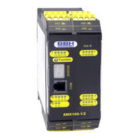
BBH SMX100-4 Installation Manual (260 pages)
Brand:
BBH
| Category:
Control Unit
| Size: 5 MB
Table of Contents
Table of Contents
4
1 Important Notes
8
Definitions
8
Co-Valid Documents
9
Abbreviations Used
11
2 Safety Regulations
13
Intended Use
13
Use in Regions with UL/CSA Requirements
13
General Safety Regulations
14
Operation and Service
15
Transport/Storage
15
3 Device Types
16
Module Overview
18
Characteristic Data of Device
20
Basic Modules
20
System Module SMX100-1(/2, /4X, /5X, /X )
20
System Module SMX100-2(/2, /4X, /5X, /X )
24
System Module SMX100-4
32
Central Expansion Modules
32
Expansion Module SMX121(/2)
32
Expansion Module SMX121-2(/2)
34
Expansion Module SMX122/122A(/2)
36
Expansion Module SMX122-2/122-2A(/2)
38
Expansion Module SMX131(/2), 131R(/2) and 131R-4/2
40
Decentralised Expansion Modules
43
Decentralised Expansion Module SMX111(/2/D)
43
Decentralised Expansion Module SMX111-2(/2/D)
47
Decentralised Expansion Module SMX112/112A(/2/D)
51
Decentralised Expansion Module SMX112-2/112-2A(/2/D)
55
Decentralised Expansion Module SMX132-0(R)/2/D / 132-1(R)/2/D
59
Communication Interface
62
Smx5X
62
Smx4X
64
Optional Universal Communication Interface
66
Encoder Specifications
68
Derating Outputs
69
Identification
69
Type Plate
69
Type Plate Smxgen2 (/2)
70
Scope of Delivery
71
4 Safety Related Characteristics
72
General Design, Safety Related Architecture and Characteristic Data
72
Safety Related Characteristic Data and Wiring for the Connected Sensors
76
Digital Sensors
76
Characteristics of Sensors / Input Elements
76
DC Digital Sensors/Inputs
77
Classification of Digital Inputs
80
Exemplary Connections of Digital Sensors
82
Overview of Achievable PI for Digital Safety Inputs
87
Sensors for Speed And/Or Position Detection
89
General Safety Related Structure of the Sensor Interface for Position And/Or Speed
89
General Diagnostic Measures for Encoder Interface
90
Encoder Types and Their Combination, Diagnostic Data
91
Specific Diagnostic Measures with Regard to the Encoder Type Used
93
Safety Relevant Cut-Off Thresholds Encoder Systems for Position and Speed Detection
94
Safety Related Assessment of Encoder Types or There Combination
97
Analog Sensors
99
Exemplary Connection of Analog Sensors
100
Safety Related Characteristic Data and Wiring of the Outputs
101
Characteristic of the Output Elements
101
Diagnoses in the Cut-Off Circuit
102
Diagnostic Functions
102
Overview DC with Respect to the Chosen Diagnostics Functions
103
Permissible Capacitive and Inductive Load at Safe Outputs
104
Digital Outputs
105
Characteristic Data of the Basic Outputs
105
Wiring Examples Basic Outputs
107
Digital Outputs I/O's (Iqqx)
114
Classification of the I/O's (Iqqx) When Used as Output
114
Wiring Examples for Safe Digital Outputs I/O's (Iqqx)
115
Overview of Achievable PI for Digital Safety Outputs
120
5 Connection and Installation
122
General Notes on Installation
122
Installation and Assembly of the SMX100 Module
124
Installation of Backplane Bus System
124
Arrangement Examples
125
SMX100-1 + SMX122 + Smx5X
125
SMX100-2 + SMX121-2 + Smx5X
125
Assembling the Modules
126
Assembly on C-Rail
126
Assembly on Backplane Bus
127
Installation und Konfiguration von Master <-> Master (SMMC) und Master <-> Slave (SDDC)
128
Network Topology
129
Installation I/O-Extension
130
Physical Address Configuration of the Slave Modules (Central/Decentral)
130
Terminal Assignment
131
Terminal Assignment SMX100-1(/2)
131
Terminal Assignment SMX100-2(/2)
133
Terminal Assignment SMX100-4(/2)
137
Terminal Assignment SMX121(/2)
142
Terminal Assignment SMX121-2(/2)
143
Terminal Assignment SMX122(/2)
145
Terminal Assignment SMX122A(/2)
147
Terminal Assignment SMX122-2(/2)
149
Terminal Assignment SMX122-2A(/2)
152
Terminal Assignment SMX111(/2/D)
155
Terminal Assignment SMX111-2(/2/D)
157
Terminal Assignment SMX112(/2/D)
159
Terminal Assignment SMX112A(/2/D)
161
Terminal Assignment SMX112-2(/2/D)
163
Terminal Assignment SMX112-2A(/2/D)
166
Terminal Assignment SMX131(/2)
169
Terminal Assignment SMX131R(/2)
171
Terminal Assignment SMX131R-4/2
174
Terminal Assignment SMX132-0/2/D
176
Terminal Assignment SMX132-0R/2/D
178
Terminal Assignment SMX132-1/2/D
180
Terminal Assignment SMX132-1R/2/D
182
External 24 VDC - Voltage Supply
185
Connection of the External Encoder Supply
187
Incremental, HTL, SIN/COS, SSI
187
Resolver
188
Connection of Digital Inputs
189
Connection of Analog Inputs
190
Connection of Position and Speed Sensors
191
General Notes
191
Assignment of Encoder Interface
193
Connection Variants
194
Connection of Absolute Encoders as Master
194
Connection of an Absolute Encoder as Slave
195
Connecting an Incremental Encoder with TTL-Signal Level
196
Connection of a SIN/COS Encoder
197
Connection of a Resolver as Master
198
Connection of a Resolver as Slave
199
Connection of Proximity Switch Smx111X Smx112X
200
Connection of Htl/Proximity Switch SMX11-2/SMX12-2
200
Configuration of Measuring Distances
203
General Description of Encoder Configuration
203
Sensor Type
203
Absolute Encoder
203
Incremental Encoder
206
Sinuscosinus Encoder - High Resolution Mode
206
Proxi Switch
207
Extended Monitoring Proximity Switch / Proximity Switch
208
HTL - Sensor
209
Resolver
209
6 Response Times of the Smx
210
Response Times in Standard Operation
210
Response Time for FAST_CHANNEL
212
Response Times for Fault Distance Monitoring
212
Reaction Times for Using Inputs and Outputs at the Expansion Modules
214
7 Start-Up
216
Procedure
216
Making Sequences
216
LED Display
218
Parameterization
219
Function Test
219
Validation
219
8 Safety Related Examination
220
9 Maintenance
221
Modification / Handling Changes to the Device
221
Exchanging a Module
221
Maintenance Intervals
221
10 Technical Data
222
Environmental Conditions
222
Safety Related Characteristic Data
222
11 Switch Types
223
12 Notes on Designing, Programming, Validating and Testing Safety Related Applications
228
Risk Assessment
228
Required Technical Documents
230
Necessary Steps for Draft, Realization and Testing
231
Specification of Safety Requirements (Structural Schematic)
233
Specification of the Functional Safety System
238
Definition of Safety Functions
238
Required Performance Level (Plr) (Additional Emergency Stop)
238
Example - Specification of Safety Functions in Form of a Table
239
Software Specification
240
Hardware Specification
242
Selection of SRP/CS and Operating Means
242
Example for Hardware Specification
243
Consideration of Systematic Failures
244
Hard and Software Design
245
Testing of the Hardware Design
245
Iterative Testing of the Achieved Safety Level
245
Verification Software(Program) and Parameters
249
Checking FUP
249
Validation of FUP against AWL and Parameters by Means of Validation Report
251
Performance of the System Test / FIT (Fault Injection Test)
253
Appendix
254
Appendix A - Classification of Switch Types
254
Appendix B - CE-Declaration
257
Advertisement
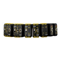
BBH SMX100-4 Installation Manual (218 pages)
SMX Modular
Brand:
BBH
| Category:
Controller
| Size: 7 MB
Table of Contents
Table of Contents
4
1 Important Notes
7
Definitions
7
Co-Valid Documents
8
Abbreviations Used
9
2 Safety Regulations
11
Intended Use
11
Use in Regions with UL/CSA Requirements
11
General Safety Regulations
12
Operation and Service
13
Transport/Storage
13
3 Device Types
14
Module Overview
16
Characteristic Data of Device
17
Basic Modules
17
Central Expansion Modules
26
Optional Communication Interface
38
Identification
43
Type Plate
43
Scope of Delivery
44
4 Safety Related Characteristics
45
General Design, Safety Related Architecture and Characteristic Data
45
Safety Related Characteristic Data and Wiring for the Connected Sensors
49
Digital Sensors
49
Sensors for Speed And/Or Position Detection
62
Analog Sensors
72
Safety Related Characteristic Data and Wiring of the Outputs
75
Characteristic of the Output Elements
75
Diagnoses in the Cut-Off Circuit
76
Permissible Capacitive and Inductive Load at Safe Outputs
78
Digital Outputs
79
Digital Outputs I/O's (Eaax)
88
5 Connection and Installation
96
General Notes on Installation
96
Installation and Assembly of the SMX100 Module
97
Installation of Backplane Bus System
97
Arrangement Examples
98
Assembling the Modules
99
Assembly on C-Rail
99
Assembly on Backplane Bus
100
Installation and Configuration IO Extension
102
Registration SMX131 to Base Device
102
Configuration of I/O Assignment SMX131
103
Logische Adresskonfiguration SMX131
103
Terminal Assignment
105
Terminal Assignment SMX 100-1
105
Terminal Assignment SMX 100-2
107
Terminal Assignment SMX 100-4
110
Terminal Assignment SMX 121
114
Terminal Assignment SMX 121-2
115
Terminal Assignment SMX 122
117
Terminal Assignment SMX 122A
119
Terminal Assignment SMX122-2
121
Terminal Assignment SMX122-2A
124
Terminal Assignment SMX 131
127
Terminal Assignment SMX131R
129
Terminal Assignment Smx1Xx/5X
131
Terminal Assignment Smx1Xx/4X
131
External 24 VDC - Voltage Supply
132
Connection of the External Encoder Supply
134
Incremental, HTL, SIN/COS, SSI
134
Resolver
135
Connection of Digital Inputs
136
Connection of Analog Inputs
137
Connection of Position and Speed Sensors
138
General Notes
138
Assignment of Encoder Interface
140
Connection Variants
141
Configuration of Measuring Distances
150
General Description of Encoder Configuration
150
6 Sensor Type
151
Absolute Encoder
151
Incremental Encoder
153
Sinuscosinus Encoder - Standard Mode
153
Sinuscosinus Encoder - High Resolution Mode
153
Proxi Switch
154
Extended Monitoring Proximity Switch / Proximity Switch
155
HTL - Sensor
156
Resolver
156
7 Response Times of the Smx
157
Response Times in Standard Operation
157
Response Time for FAST_CHANNEL
159
Response Times for Fault Distance Monitoring
159
Reaction Times for Using Inputs and Outputs at the Expansion Modules
161
8 Start-Up
163
Procedure
163
Switch-On Sequences
163
Reset Behavior
165
Reset Types and Triggering Element
165
Reset-Timing
166
Reset Functions
166
LED Display
171
Parameterization
172
Function Test
172
Validation
172
9 Safety Related Examination
173
10 Maintenance
174
Modification / Handling Changes to the Device
174
Exchanging a Module
174
Maintenance Intervals
174
11 Technical Data
175
Environmental Conditions
175
Safety Related Characteristic Data
175
12 Debugging
176
SMX Error Types
176
Display of Error Types
177
SMX100-X Without Expansion Module
177
SMX100-X with Expansion Module
177
13 Switch Types
178
14 Notes on Designing, Programming, Validating and Testing Safety Related Applications
183
Risk Assessment
183
Required Technical Documents
185
Necessary Steps for Draft, Realization and Testing
186
Phases of the V-Model
187
Specification of Safety Requirements (Structural Schematic)
188
Specification of the Functional Safety System
192
Software Specification
195
Hardware Specification
197
Hard and Software Design
200
Testing of the Hardware Design
200
Verification Software(Program) and Parameters
204
Performance of the System Test / FIT (Fault Injection Test)
209
Appendix
210
Appendix A - Classification of Switch Types
210
Appendix B - CE-Declaration
213
Appendix C - Product List
217
Advertisement
Related Products
BBH SMX100-4/2
BBH SMX100-4/4x
BBH SMX100-4/5x
BBH SMX100-4/2/x
BBH SMX100-1
BBH SMX100-1/2
BBH SMX100-2/2
BBH SMX100-1/4x
BBH SMX100-1/5x
BBH SMX100-2/2/x
BBH Categories
Controller
Personal Care Products
Measuring Instruments
Battery Charger
Network Hardware
More BBH Manuals
Login
Sign In
OR
Sign in with Facebook
Sign in with Google
Upload manual
Upload from disk
Upload from URL