
Subscribe to Our Youtube Channel
Related Manuals for Eaton Ulusoy URING36 F-SF6


Summary of Contents for Eaton Ulusoy URING36 F-SF6
- Page 1 Ulusoy URING36 F - SF Insulated Transformer Protection RMU Switchgear with Fuse and LBS User Manual...
-
Page 2: Table Of Contents
CONTENTS SWITCHGEAR INTRODUCTION FUSE SELECTION FOR TRANSFORMER PROTECTION PLACING THE FUSES SWITCHGEAR DIMENSIONS AND CHECKS BEFORE POWERING USE TEST TO BE PERFORMED BEFORE POWERING OPERATIONAL INSTRUCTIONS OPERATIONAL INSTRUCTIONS: EARTHING DISCONNECTOR MANEUVERS OPERATIONAL INSTRUCTIONS: LOAD DISCONNECTOR MANEUVERS ATTACHING PADLOCK REPLACING THE VOLTAGE INDICATOR TROUBLESHOOTING ELECTRIC TERMINAL SCHEME... -
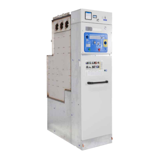
Page 3: Switchgear Introduction
SWITCHGEAR INTRODUCTION VOLTAGE INDICATOR LIGHTS SIGNAL LIGHT BOX TYPE LABEL OPSİYONELDİR SPRING ASSEMBLY HOUSING PADLOCK HOUSING MECHANICAL ON-OFF BUTTONS DİKKA T FLBSG 36 SİGO RT AL I RMU www .ulusoyel e ktr ik.com .tr EARTHING DISCONNECTOR INSTALLA- TION HOUSING OPERATION SEQUENCE LABEL REMOTE CONTROL SOCKET SINGLE LINE SCHEME LOW VOLTAGE BOARD... -
Page 4: Fuse Selection For Transformer Protection
FUSE SELECTION FOR TRANSFORMER PROTECTION Fuse values for GMH 36-02 cells depend on the voltage and power ( kVA values ) of the transformer to be protected. Fuse selection tables according to manufacturers are below. Select the fuse amperages from the lists below according to the power of the transformer you will use and according to the fuse brand you will use. -
Page 5: Placing The Fuses
PLACING THE FUSES IN THE SWITCHGEAR SWITCH OFF THE EARTHING TURN THE FUSE PLUG LEFT. REMOVE THE PLUG INSIDE DISCONNECTOR AND OPEN THE THE FUSE SHELL FROM THE CELL FRONT COVER. HOUSING. ASSEMBLE THE MEDIUM AFTER PLACING THE MEDIUM AFTER PLACING THE FUSE PLUG VOLTAGE FUSE BY PLACING IT VOLTAGE FUSE INTO THE SHELL, INTO THE SHELL, ROTATE RIGHT... - Page 6 DIMENSIONS (in millimeters) FLBSG 36 1050 Checks before powering the switchgear Check if there are foreign objects in the switchgear. Check the connections of the cells. Check if all fuses are placed correctly in all phases. Place the switchgear front cover. Check if the front cover is placed correctly.
-
Page 7: Use Test To Be Performed Before Powering
USE TEST TO BE PERFORMED BEFORE POWERING (See the operational instructions section) Operation order Padlock label Load disconnector İŞLEM SIRASI Switching Position indicator spring TOPRAK YÜK HÜCRE HÜCRE YÜK HÜCREDE TOPRAK KAP ISINI AYIRICISIN I YAY KUR AYIRICISINI AYIRICISINI ISLEM AYIRICISINI KAP ISINI EVET... -
Page 8: Operational Instructions
OPERATIONAL INSTRUCTIONS Manual use and front appearance İŞLEM SIRASI HÜCRE TOPRAK YÜK YÜK HÜCREDE TOPRAK HÜCRE KAP ISINI AYIRICISINI YAY KUR AYIRICISINI AYIRICISINI ISLEM AYIRICISINI KAP ISINI EVET KAPA T AÇ KAPA T AÇ VAR MI? KAPA T AÇ HAYIR DİKKAT BU HÜCRE GİRİŞ... - Page 9 OPERATIONAL INSTRUCTIONS Earthing disconnector maneuvers İŞLEM SIRASI Turning the earthing disconnector on: Place the assembly lever into the DİKKAT earthing disconnector assembly BU HÜCR E GİRİŞ HÜCR ESİ OLARAK KULLANILIYOR İSE,BİRÖNC EKİ FLBSG 36 MERKEZDEN ENERJİSİNİ KESMEDEN TOPRAK AYIRICISINI KAPATMAYINIZ. SİGORTALI RMU housing as shown in the figure and 36kV / 200A / 16kA...
- Page 10 OPERATIONAL INSTRUCTIONS Load disconnector maneuvers İŞLEM SIRASI Assembling the closing spring: Place the assembly lever to spring assembly housing as shown in the figure and rotate it in arrow direction. DİKKAT Ensure that it makes the assembly sound when assembling the BU HÜCR E GİRİŞ...
-
Page 11: Attaching Padlock
OPERATIONAL INSTRUCTIONS Load disconnector maneuvers İŞLEM SIRASI Turning the load disconnector on: To turn the load disconnector on, press the on button. DİKKAT BU HÜCR E GİRİŞ HÜCR ESİ OLARAK KULLANILIYOR İSE,BİRÖNC EKİ FLBSG 36 MERKEZDEN ENERJİSİNİ KESMEDEN Or plug the remote control given with the cell group into TOPRAK AYIRICISINI KAPATMAYINIZ. -
Page 12: Replacing The Voltage Indicator
SAFE OPERATION Cell front cover can only be removed or attached when the earthing disconnector is off. REPLACING THE VOLTAGE INDICATOR Voltage indicator To replace a faulty voltage indicator; Open the front cover of low voltage assembly board of the cell Remove the faulty indicator by dismantling its latches and replace it with a new one. -
Page 13: Troubleshooting
TROUBLESHOOTING Voltage indicator light / lights are blown. Voltage indicator Voltage indicator connection cable socket may be fallen off. Light / lights are off. Check if the load disconnector is off. Check if the earthing disconnector is off. Cell front cover cannot be turned on or off. If on, turn off. - Page 14 Eaton’s mission is to improve the quality of life and the environment through the use of power management technologies and services. We provide sustainable solutions that help our customers effectively manage electrical, hydraulic, and mechanical power - more safely, more efficiently, and more reliably.
Need help?
Do you have a question about the Ulusoy URING36 F-SF6 and is the answer not in the manual?
Questions and answers