
Related Manuals for LabelMill LM3510


Summary of Contents for LabelMill LM3510
- Page 1 LM3510 PRINT & APPLY OPERATIONS MANUAL Manufactured in USA by: 2416 Jackson St. LabelMill, Inc. Savanna, IL 61074 (800) 273-4707 info@labelmill.com www.labelmill.com...
-
Page 2: Table Of Contents
LM3510 Print & Apply Label Applicator USER'S MANUAL TABLE OF CONTENTS SECTION PAGE 1. APPLICATOR OVERVIEW Introduction 1-01 General Printer Specifications 1-02 Inventory List 1-03 Print & Apply Component Description 1-04 User Responsibility 1-05 Safety 1-05 2. SETUP AND OPERATION... -
Page 3: Applicator Overview
LM3510 Print & Apply Label Applicator USER’S MANUAL SECTION 1 APPLICATOR OVERVIEW Introduction 1-01 General Printer Specifications 1-02 Inventory List 1-03 Print & Apply Component Description 1-04 User Responsibility 1-05 Safety 1-05 Page 3 Made in the U.S.A. © 2019 LABELMILL... - Page 4 Centronics Parallel Interface Port, Ethernet or serial port, on the Printer/Applicator. Once the format is downloaded to the Printer Job Buffer, the LM3510 system can print and apply as normal. Standard industry label software packages can be used in conjunction with a PC to design and load label design.
- Page 5 LM3510 Print & Apply Label Applicator USER’S MANUAL SPECIFICATIONS PRINT SPEED Up to 12”/second and approx. 90 labels/min. (Varies depending on label and product size.) BAR CODES Linear and Two-Dimensional Barcodes BAR CODE RATIOS 1:2, 1:2.5, 1:3 or individually programmable bar code widths...
-
Page 6: Inventory List
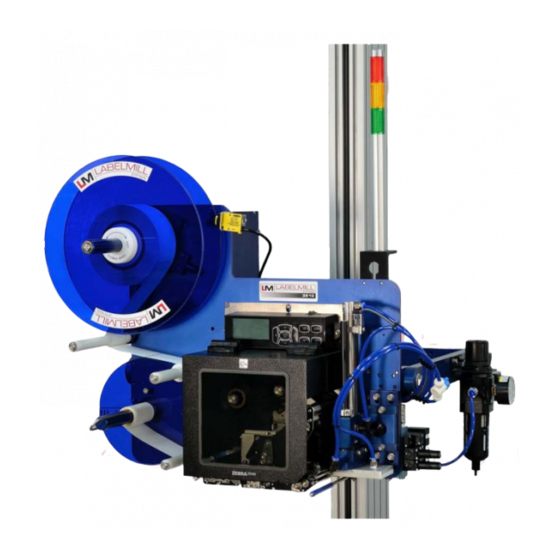
LM3510 Print & Apply Label Applicator USER'S MANUAL INVENTORY LIST QTY. Description Print & Apply Assembly 12-½” dia. Blue Plastic Spools w / Quick Release Collar 7-¾” dia. Blue Plastic Spool w / screws ½” - 13 bolts w / washers... - Page 7 LM3510 Print & Apply Label Applicator USER’S MANUAL COMPONENT DESCRIPTION / LOCATION TAMP ALARM LABEL SPOOL CYLINDER STACK REED SWITCH SPOOL LOCK U-ARM AIR FILTER/ REGULATOR BRAKE ARM VALVE PACK WEB TAKE-UP SPOOL WEB GUIDE SWING AWAY ROLLERS TAMP ASSEMBLY...
-
Page 8: User Responsibility
LM3510 Print & Apply Label Applicator USER'S MANUAL USER RESPONSIBILITY This equipment will perform in conformity with the description thereof contained in this manual and accompanying labels and / or inserts when installed, operated, maintained, and repaired in accordance with the instructions provided. -
Page 9: Setup And Operation
LM3510 Print & Apply Label Applicator USER’S MANUAL SECTION 2 SETUP AND OPERATION Web Routing 2-01 Thermal Print Head Label Loading 2-03 Thermal Ribbon Loading 2-03 Label Sensor Adjustment 2-03 Take Up Unit Assembly 2-04 Clutch Assembly Adjustment 2-05 Hand Held Labeler Interface HLI-100... -
Page 10: Web Routing
LM3510 Print & Apply Label Applicator USER'S MANUAL WEB ROUTING Step Operation Load web onto label storage spool (A) so it unloads in a clockwise direction. Feed the web to the left and below roller guide (B), to the right of roller (C) and to the left and below roller guide (D). - Page 11 LM3510 Print & Apply Label Applicator USER’S MANUAL SPOOL LOCK SPOOL LOCK REMOVAL: To remove the label storage spool (A), turn the spool lock counterclockwise until you reach a stop. The spool will now slide off. To secure the spool, simply turn the spool lock clockwise until snug. DO...
-
Page 12: Thermal Ribbon Loading
LM3510 Print & Apply Label Applicator USER'S MANUAL LOADING THERMAL PRINT HEAD REFER TO PRINTER MANUAL LABEL & RIBBON ROUTING REFER TO PRINTER MANUAL THERMAL RIBBON LOADING REFER TO PRINTER MANUAL NOTE: The printer will not operate unless the front cover is in the fully closed position. For your continued safety, do not override the front cover interlock switch. -
Page 13: Take Up Unit Assembly
LM3510 Print & Apply Label Applicator USER’S MANUAL TAKE-UP UNIT ASSEMBLY The Take-Up Assembly is located on the backside of the main panel. To adjust the clutch, the side panels must be removed to gain access. To remove the Clutch Assembly, you must first remove the Web Take-Up Spool. -
Page 14: Clutch Assembly Adjustment
LM3510 Print & Apply Label Applicator USER'S MANUAL CLUTCH ADJUSTMENT (A) DRIVE DOG (B) SHAFT WHEEL (C) FRICTION DISC (D) PRESSURE PLATE (E) THRUST BEARING (F) PRESSURE SPRING (G) TENSION ADJ. COLLAR To increase waste web tension, move the shaft wheel (B) 1/32” toward the Spool. To reduce web tension, move the shaft wheel (B) 1/32”... -
Page 15: Hand Held Labeler Interface Hli-100
LM3510 Print & Apply Label Applicator USER’S MANUAL HAND HELD LABELER INTERFACE HLI-100 OPERATOR LCD DISPLAY INTERFACE INTERFACE PORT 2-06 Page 15 Made in the U.S.A. © 2019 LABELMILL 11/01/2019 Model LM3510... - Page 16 LM3510 Print & Apply Label Applicator USER'S MANUAL ACCESSORY CONNECTIONS LOCATED ON BACK OF LABELER CONTROL ENCLOSURE TOUCH SCREEN SERIAL INTERFACE TO HLI-100 HAND HELD LABELER INTERFACE THERMAL PRINTER DB-25 AUX I/O INTERFACE CONNECTOR LIGHT BAR / AUX VALVE PACK...
-
Page 17: T-50 Photo Eye
LM3510 Print & Apply Label Applicator USER’S MANUAL T-50 PHOTO EYE Trigger Cable Wiring 2-08 Page 17 Made in the U.S.A. © 2019 LABELMILL 11/01/2019 Model LM3510... -
Page 18: Air Assist Tube
LM3510 Print & Apply Label Applicator USER'S MANUAL AIR ASSIST TUBE The Air Assist Tube must be adjusted to clear the trailing edge of the printed labels and the Label Platen. An adjustment screw is used to adjust the position of the air holes in relation to the labels. - Page 19 LM3510 Print & Apply Label Applicator USER’S MANUAL OPTIONAL T-150 MOUNTING STAND 2-12 Page 19 Made in the U.S.A. © 2019 LABELMILL 11/01/2019 Model LM3510...
-
Page 20: T-Stand Adjustment
LM3510 Print & Apply Label Applicator USER'S MANUAL T-STAND ADJUSTMENT Column Crank Column Lock 2-11 Page 20 Made in the U.S.A. © 2019 LABELMILL 11/01/2019 Model LM3510... -
Page 21: Tamp Unit Operation
LM3510 Print & Apply Label Applicator USER’S MANUAL TAMP UNIT OPERATION • Tamp Duration Tamp duration is used to provide an on timer for the solenoid valve on the main tamp cylinder. The delay on standard versions can be from 0 to 30.000 seconds in 1/1000 of a second accuracy. This allows for easy change over from one product height to another without physically changing the height of the unit. -
Page 22: Tamp Flow Control Adjustment
LM3510 Print & Apply Label Applicator USER'S MANUAL TAMP FLOW CONTROL ADJUSTMENT Regulator Adjustment: Clockwise - Increase pressure Counterclockwise - Decrease pressure MAIN AIR REGULATOR Controls maximum air pressure available to entire applicator. Should be set between 40 and 80 PSI. -
Page 23: Optional Tamp Applicator
LM3510 Print & Apply Label Applicator USER’S MANUAL OPTIONAL TAMP APPLICATOR 2-14 Page 23 Made in the U.S.A. © 2019 LABELMILL 11/01/2019 Model LM3510... -
Page 24: Optional Corner Wrap Applicator
LM3510 Print & Apply Label Applicator USER'S MANUAL OPTIONAL CORNER WRAP APPLICATOR 2-15 Page 24 Made in the U.S.A. © 2019 LABELMILL 11/01/2019 Model LM3510... -
Page 25: Optional Adjacent Panel Applicator
LM3510 Print & Apply Label Applicator USER’S MANUAL OPTIONAL ADJACENT PANEL APPLICATOR 2-16 Page 25 Made in the U.S.A. © 2019 LABELMILL 11/01/2019 Model LM3510... -
Page 26: Optional Table-Top Applicator
LM3510 Print & Apply Label Applicator USER'S MANUAL OPTIONAL TABLE-TOP APPLICATOR 2-17 Page 26 Made in the U.S.A. © 2019 LABELMILL 11/01/2019 Model LM3510... -
Page 27: Control Box
LM3510 Print & Apply Label Applicator USER’S MANUAL SECTION 3 CONTROL BOX Programming 3-01 Quick Reference Chart 3-05 Key Definitions 3-16 Set Up of Key Features & Quick Start 3-17 Description of I/O 3-25 Page 27 Made in the U.S.A. - Page 28 LM3510 Print & Apply Label Applicator USER'S MANUAL PROGRAMMING All programming is performed via the HLI-100 keypad and display as shown on page 2-6. All programmed settings are backed in nonvolatile memory and are not lost when the unit is powered off.
- Page 29 LM3510 Print & Apply Label Applicator USER’S MANUAL • PASSWORD The PASSWORD is used to lock the menus of the control. This option is used to prevent unauthorized access to variable data. When shipped from the factory, the pass word is to 7074 and NO MENUS are locked. The password cannot be changed.
- Page 30 LM3510 Print & Apply Label Applicator USER'S MANUAL • TAKE UP This is used to delay the start and stop of the take up motor. PROGRAMMABLE BLOCKS: Start delay – delays (x) seconds after start print before starting take up motor.
- Page 31 LM3510 Print & Apply Label Applicator USER’S MANUAL • CYCLE TYPE Cycle Type determines the application type and sequence in relation to the label feed. PROGRAMMABLE BLOCKS: No Tamp – Not normally used Tamp Before Feed – (standard) Tamps label first, prints label second Tamp After Feed –...
- Page 32 LM3510 Print & Apply Label Applicator USER'S MANUAL QUICK PROGRAMMING CHART MODEL NUMBER & REVISION LM MODEL 3510 TOTAL 000000 UP AND DOWN ARROW KEYS WILL SCROLL PRESS THROUGH THE PROGRAM BLOCKS "PROG" AND THE SUB MENUS PASS WORD PRESS "ENTER"...
- Page 33 LM3510 Print & Apply Label Applicator USER’S MANUAL PRINT TYPE PRESS "ENTER" ENCODER PRESS "ENTER" CYCLE TYPE PRESS "ENTER" JOB STORAGE PRESS "ENTER" DEFAULTS PRESS "ENTER" I/O STATUS PRESS "ENTER" PRESS "PROG" 3-06 Page 33 Made in the U.S.A. © 2019 LABELMILL...
- Page 34 LM3510 Print & Apply Label Applicator USER'S MANUAL MAIN DISPLAYS PASSWORD 0000 PASSWORD PRESS ENTER PASSWORD PASSWORD Note: use UP and DOWN arrows to toggle between "ON" and "OFF". The enter key will save selection. 3-07 Page 34 Made in the U.S.A.
- Page 35 LM3510 Print & Apply Label Applicator USER’S MANUAL 3-08 Page 35 Made in the U.S.A. © 2019 LABELMILL 11/01/2019 Model LM3510...
- Page 36 LM3510 Print & Apply Label Applicator USER'S MANUAL TAMP SETUP TAMP DURATION TAMP DUR 0.000 PRESS ENTER PRESS ENTER FLAG DURATION FLAG DUR 00.00 PRESS ENTER HEAD UP SWITCH HEAD UP SWITCH PRESS ENTER N.O. HEAD UP SWITCH NONE HEAD UP DEBOUNCE HD DBOUNCE 0.020...
- Page 37 LM3510 Print & Apply Label Applicator USER’S MANUAL AUX TAMP SETUP TAMP DURATION TAMP DUR 00.000 PRESS ENTER PRESS ENTER PRODUCT DELAY PROD DLY 00.000 PRESS ENTER MAX 0.5000 SECONDS TAKEUP START DELAY START DELAY 0.000 PRESS ENTER PRESS ENTER STOP DELAY STOP DLY 0.000...
- Page 38 LM3510 Print & Apply Label Applicator USER'S MANUAL COUNTER ENTER TO CLEAR PRESS ENTER ESC TO ABORT 3-11 Page 38 Made in the U.S.A. © 2019 LABELMILL 11/01/2019 Model LM3510...
- Page 39 LM3510 Print & Apply Label Applicator USER’S MANUAL ENCODER ENCODER ON / OFF ENCODER ON / OFF PRESS ENTER PRESS ENTER ENC OVERRIDE % % OVERRIDE 100.0 PRESS ENTER TRIGGER DIST TRIG DIST 00.00 PRESS ENTER START COMP DIST ST CMP DIS 0.000...
- Page 40 LM3510 Print & Apply Label Applicator USER'S MANUAL 3-13 Page 40 Made in the U.S.A. © 2019 LABELMILL 11/01/2019 Model LM3510...
- Page 41 LM3510 Print & Apply Label Applicator USER’S MANUAL JOB STORAGE RESTORE JOB JOB NUMBER 0 PRESS ENTER PRESS ENTER SAVE JOB JOB NUMBER 0 PRESS ENTER RANGE 1 TO 6 CAN NOT SAVE OR DELETE JOB JOB NUMBER 0 RESTORE...
- Page 42 LM3510 Print & Apply Label Applicator USER'S MANUAL I/O STATUS S P H I A F V T DISPLAY MAIN I/O PRESS ENTER 0 0 0 0 0 X 0 0 = OFF X = ON I/O Ports are numbered...
-
Page 43: Key Definitions
LM3510 Print & Apply Label Applicator USER’S MANUAL KEY DEFINITIONS • ASYNCHRONOUS OPERATION – The term “ASYNCHRONOUS OPERATION” is used because the speed of the printer applicator motor (label speed) does not necessarily match the speed of the product conveyor. In other words their speed is set independently of one another and has NO interrelation. -
Page 44: Setup Of Key Features
LM3510 Print & Apply Label Applicator USER'S MANUAL QUICK START 1. Inspect applicator system and verify all cables are installed properly. 2. Web system with labels. 3. Turn power switch on. 4. Press “PROG” 5. Press down arrow 6. Enter Defaults 7. - Page 45 LM3510 Print & Apply Label Applicator USER’S MANUAL • TAMP OR BLOW WITH AN ENCODER Determine the following and select it in the software 1. Type of application mode. (Tamp, or Blow) (refer to above) 2. Tamp or blow before or after feed (before feed is standard) 3.
- Page 46 LM3510 Print & Apply Label Applicator USER'S MANUAL • CALCULATING ENCODER LINES PER INCH (gearing) There are two basic concepts utilized to interface the product ENCODER to the Label Mill control. One method utilizes a wheel mounted directly to an encoder. This wheel rests on the belt surface and rotates when the belt moves.
- Page 47 LM3510 Print & Apply Label Applicator USER’S MANUAL • TRIGGER DIST – TRIGGER DISTANCE TRIGGER DISTANCE is used in conjunction with the encoder feature ONLY. Trigger distance is similar to product delay in that it is used to electronically move the placement of the label on the product. When the encoder feature is used, the product delay feature is rendered inactive.
- Page 48 TAMP / BLOW WITHOUT AN ENCODER WITH TWO TRIGGER PHOTO EYES Variable data application is utilized when the LM3510 is interfaced with a scale or other equipment that will be transmitting a DIFFERENT label format to the applicator for every label that is applied. When this option is activated, the use of the pre-print photo eye (option) is required.
- Page 49 TAMP / BLOW WITH AN ENCODER WITH TWO TRIGGER PHOTO EYES Variable data application is utilized when the LM3510 is interfaced with a scale or other equipment that will be transmitting a DIFFERENT label format to the applicator for every label that is applied. When this option is activated, the use of the pre-print photo eye (option) is required.
- Page 50 LM3510 Print & Apply Label Applicator USER'S MANUAL HOW TO APPLY MULTIPLE LABELS TO A SINGLE PRODUCT Product delay is used to electronically move the placement of the FIRST label on the product. Product delay will move the label placement in time (00.000). Because the product delay feature utilizes time, the speed of the product MUST be constant and consistent.
- Page 51 LM3510 Print & Apply Label Applicator USER’S MANUAL HOW TO APPLY MULTIPLE LABELS TO A SINGLE PRODUCT • WHEN UTILIZING A ENCODER This section will explain how to apply more than one label to a single product with a single start signal. TRIGGER DISTANCE will move the label placement in inches (00.00) for the FIRST LABEL.
-
Page 52: Description Of I/O
LM3510 Print & Apply Label Applicator USER'S MANUAL DESCRIPTION OF I/O LEGEND 24V OPT: 24V OPTO INPUT WITH INTERNAL 24V COMMON HIGH CURRENT OUTPUT Rated @ 500ma All user inputs and outputs are “SINKING” type. Example in order for a status light to illuminate for “Run Status Ok”... - Page 53 LM3510 Print & Apply Label Applicator USER’S MANUAL PRINT AND APPLY INTERFACE PIN # ADDRESS PAPER END INPUT X0,5 PRINTER GROUND RIBBON END INPUT X0,6 PRINTER ERROR INPUT X0,7 PRINT START OUTPUT Y0,5 PRINT END INPUT X1,0 REPRINT OUTPUT Y0,6 N.C.
- Page 54 LM3510 Print & Apply Label Applicator USER'S MANUAL LIGHT BAR/AUXILIARY CONNECTOR INPUT/ DB-15 FEMALE PIN # OUTPUT ADDRESS +24VDC +24VDC 24 COM 24 COM LOW LABEL IN X1,3 ERROR LIGHT (Red light) Y0,7 LOW LABEL (Yellow light) Y1,0 RUN STATUS OK (Green Light)
- Page 55 LM3510 Print & Apply Label Applicator USER’S MANUAL AUX I/O INPUT/ DB25 Female CONNECTOR #J1 PIN # OUTPUT ADDRESS +24VDC +24VDC 24V COM 24V COM Input Common Pin 5 and 1 tied for sinking inputs, pin 5 to pin 3 for...
- Page 56 LM3510 Print & Apply Label Applicator USER'S MANUAL E-STOP Wiring (J1 ONLY) DB15 +24 TO OUTPUTS MCR TO CPU POWER TO SERVO CARD 3-29 Page 56 Made in the U.S.A. © 2019 LABELMILL 11/01/2019 Model LM3510...
- Page 57 LM3510 Print & Apply Label Applicator USER’S MANUAL Display COMM. PIN # 8 Pin RJ 422 Touch Screen Touch Sense (GND) Fault line O.C. Display COMM. PIN # 6 Pin RJ 232 Hand Held COMM. 1 RS-232 DB9 Female PIN #...
- Page 58 LM3510 Print & Apply Label Applicator USER'S MANUAL CONVEYOR ENCODER DB9 Male PIN # 2ENC A+ 2ENC A- 2 ENC B+ 2 ENC B- +5 vdc Shield Take-Up ADDRESS Amp 9 PIN LM3510 PIN # Capacitor / Neutral 120VAC Crydom output Y0,4...
-
Page 59: Troubleshooting
LM3510 Print & Apply Label Applicator USER’S MANUAL SECTION 4 CLEANING & MAINTENANCE Troubleshooting 4-01 Fault Codes 4-02 Maintaining the Air Slide 4-03 Replacing the Power Fuse 4-04 Page 59 Made in the U.S.A. © 2019 LABELMILL 11/01/2019 Model LM3510... - Page 60 LM3510 Print & Apply Label Applicator USER'S MANUAL TROUBLESHOOTING GUIDE If the system malfunctions, it is necessary to determine where the problem exists in a normal sequence of operation. The procedure of the unit is outlined in the left hand column of the table below to provide a systematic approach to troubleshooting.
- Page 61 LM3510 Print & Apply Label Applicator USER’S MANUAL FAULT MESSAGES DISPLAYED FAULT FAULT CORRECTIVE ACTION Print Time Out Printer failed to print or Printer Off Line Control failed to receive a “End No Label Formats Loaded Print Signal” Check Printer Interface Cable...
-
Page 62: Maintaining The Air Slide
LM3510 Print & Apply Label Applicator USER'S MANUAL MAINTAINING THE AIR SLIDE Very little maintenance is required to keep the Tamp Assembly’s air slide in good working condition. To maintain the air slide, simply remove the air lines from the air slide and place 1-2 drops of any approved air motor oil into the air inlets at least once a month. -
Page 63: Replacing Main Power Fuse
LM3510 Print & Apply Label Applicator USER’S MANUAL REPLACING THE MAIN POWER FUSE The circuitry is protected from a current overload by GMA 10A a fast blow fuse. Should the applier fail to operate, the condition of this fuse should be checked. If the fuse is open, the cause of the overload condition must be determined and corrected prior to replacing the fuse. - Page 64 LM3510 Print & Apply Label Applicator USER'S MANUAL LM3510 PRINT & APPLY OPERATIONS MANUAL Copyright and Trademarks Copyright ©2019 All rights reserved. All trademarks and brand names are the property of their respective owners. LabelMill 2416 Jackson St. Savanna, IL 61074 Phone: (800) 273-4707;...
Need help?
Do you have a question about the LM3510 and is the answer not in the manual?
Questions and answers