Advertisement
Quick Links
Advertisement

Related Manuals for E-Z DRILL 210B SRA


Summary of Contents for E-Z DRILL 210B SRA
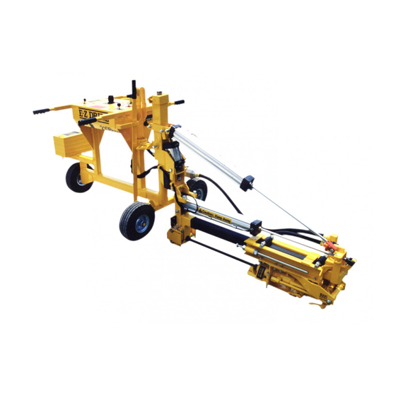
- Page 1 SETTING UP THE MODEL 210B SRA...
- Page 2 SAFETY PRECAUTIONS FOR THE MODEL 210B SRA System Under Pressure: Shut off air supply and disconnect air hose before disassembling or disconnecting parts. Flying Debris: During boring, chips may be ejected. Stay behind control panel and wear safety glasses to prevent eye injury.
- Page 3 SAFETY PRECAUTIONS FOR THE MODEL 210B SRA (continued) Loud Noise: Wear ear protection to prevent eardrum damage from air compressor. Dust: Wear a dust protection mask to protect from concrete dust. High Pressure: High pressure from the air compressor can damage the drill, and can void the warranty.
- Page 4 ATTACHING THE HOSE THE DRILL UNIT • The Model 210B SRA requires a minimum ¾” hose and a minimum of 100 cfm of air. • Make sure all safety precautions are followed with the hose and all hose connections. • IMPORTANT: AIR COMPRESSOR MUST MAINTAIN...
- Page 5 SET UP FOR THE MODEL 210B SRA • Always keep the lever on the rock shown at right in line with the drill motor. • If the lever is in the position shown at right, the air will be shut off from...
- Page 6 However, a 7/8” x 4 ¼” chuck and 1” x 4 ¼” chuck are available on request. • All 210 series E-Z Drill models use 6” of the usable length of the bit (i.e. a 24” bit will drill up to 18” deep; an 18”...
- Page 7 INSTALLING THE DRILL BITS • IMPORTANT: You must have the correct bit guide bushing to match the bit you will be using: For drilling a: 5/8” diameter hole, use 1108 MCP 3/4” diameter hole, use 1109 MCP 7/8” diameter hole, use 1110 MCP 1”...
- Page 8 INSTALLING THE DRILL BITS • To install a drill bit, loosen the swivel bolt until you can swing it out away from the lower bit guide. • NOTE: You can use the wrench provided on the side of the control panel.
- Page 9 INSTALLING THE DRILL BITS • Open the retainer latch on the drill motor.
- Page 10 INSTALLING THE DRILL BITS • Place the bit into the chuck and close the latch. • Close the bit guide around the bit and tighten the swivel bolt.
- Page 11 INSTALLING THE DRILL BITS • You may have to adjust the return stop rod so that the end of the bits clears the bit guide.
- Page 12 INSTALLING THE DRILL BITS • To adjust the stop rods, loosen the stop rod nuts. Move the stop rod in the direction needed to the required location and re-tighten the nuts.
- Page 13 INSTALLING THE DRILL BITS • If you are using 2-piece H- thread bits, you may also have to adjust the guide plates. • Newer models have guide wheels installed in place of the guide plates. These wheels are also adjustable.
- Page 14 ADJUSTING THE HEIGHT OF THE DRILL SYSTEM • Adjusting the height of the drill systems is done by turning the mast screw jack assembly located at the top of the mast. Before turning the screw jack, you must first loosen the ½” x 1 ½”...
- Page 15 ADJUSTING THE HEIGHT OF THE DRILL SYSTEMS • Again, you can use the wrench provided with the drill unit to turn the nut at the top of the mast. As soon as you have adjusted the mast to the required height, re- tighten the bolts on the side of the mast.
- Page 16 LEVELING THE DRILL SYSTEMS IMPORTANT: BEFORE LEVELING THE DRILL SYSTEMS, CONFIRM THE ANGLE REQUIRED. MANY TIMES THE DRILL SYSTEM IS NOT BE “LEVEL WITH THE WORLD”, THEY SHOULD BE SET DRILL PARALLEL WITH THE TOP OF THE CONCRETE SLAB INTO WHICH YOU ARE DRILLING.
- Page 17 LEVELING THE DRILL SYSTEMS • On the all-thread coming out of the bottom of the Auto Align cylinder, turn the top nut to change the angle of the drill system.
- Page 18 LEVELING THE DRILL SYSTEMS NOTE: THIS ADJUSTMENT WILL BE REQUIRED ANYTIME YOU HAVE BEEN DRILLING HORIZONTAL HOLES, AND WANT ADJUST TO DRILL STRAIGHT VERTICAL HOLES, OR VICE VERSA.
-
Page 19: Setting The Drill Depth
SETTING THE DRILL DEPTH • To adjust the drills to ensure the desired depth, make sure all other adjustments have been made and the air supply is connected to the drill. Maneuver the drill to the edge of the concrete slab. Heavy Load: Use handles to reposition the drill unit. - Page 20 SETTING THE DRILL DEPTH • MAKE SURE AIR SUPPLY IS ON TO THE DRILL UNIT, AND THE “RAISE & LOWER” VALVE IS IN THE “RAISE” POSITION BEFORE DOING THE NEXT STEPS. • Pinch Points: Keep hand clear of carriage assembly and Raise & Lower Cylinder.
- Page 21 SETTING THE DRILL DEPTH • You can store the lock pin in the holes in bracket next to the red safety latch.
- Page 22 SETTING THE DRILL DEPTH • Place the “Raise & Lower” valve into the “LOWER” position. The drill system will now lower into the horizontal position. • Activating this control will cause the drill system lower down to the horizontal position. Make sure everyone is clear of the drill unit before lowering the drill system...
- Page 23 SETTING THE DRILL DEPTH • Place the “Auto-Align” switch to the “DOWN” position. • If the guide plates/guide wheels are not touching the surface of the concrete, place the Auto-Align switch to “UP” position and maneuver the drill until they do.
- Page 24 SETTING THE DRILL DEPTH • Place the Feed Lever into the “IN” position. The drill will move forward until the bit contacts the concrete slab.
- Page 25 SETTING THE DRILL DEPTH • Measure the distance from the head of the stop rod to the rubber stop pad. If this is not the required drill distance, loosen the stop rod nuts and move the stop rod the desired distance from the stop pad.
- Page 26 CHECKING THE IN-LINE OILER DO NOT REMOVE CAP UNDER PRESSURE ! (to remove pressure from system, have air supply disconnected from drill unit, and open the Power lever to the “On” position) • Using the wrench provided on the back of the control panel, remove the oiler cap from the oiler.
- Page 27 RECOMMENDED SPECIFICATIONS FOR ROCK DRILL LUBRICANT The use of synthetic oils is NOT RECOMMENDED due to possible damage to seals, “O” rings, hoses, blades, and polycarbonate oiler/filter bowls. Use only a non-detergent, Class 2, pneumatic lubricating oil (viscosity 100-200 S.S.U. @ 100° F and minimum aniline point of 200°F); which contains no synthetic additives;...
- Page 28 CHECKING THE IN-LINE OILER • Fill the oiler to the top of the adjustment screw. The oiler should run approximately four hours before needing refilled. • If you need to make an adjustment to the flow, use a screwdriver to turn the screw to a higher number for more flow, or to a lower number for less flow.
Need help?
Do you have a question about the 210B SRA and is the answer not in the manual?
Questions and answers