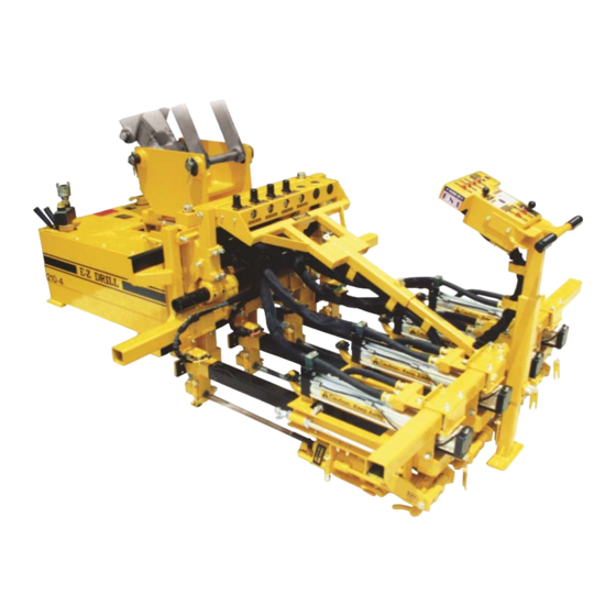
E-Z DRILL 210-3 EQ MT Setting Up
Hide thumbs
Also See for 210-3 EQ MT:
- Maintenance manual (13 pages) ,
- Operating instructions manual (25 pages)
Advertisement
Quick Links
Advertisement

Related Manuals for E-Z DRILL 210-3 EQ MT


Summary of Contents for E-Z DRILL 210-3 EQ MT
- Page 1 SETTING UP THE MODEL 210-3, -4 , and -5 EQ MT...
- Page 2 SAFETY PRECAUTIONS FOR THE MODEL 210-3, -4, -5 EQ MT System Under Pressure: Shut off air supply and disconnect air hose before disassembling or disconnecting parts. Flying Debris: During boring, chips may be ejected. Stay behind control panel and wear safety glasses to prevent eye injury. Pinch Points: Keep hand clear of carriage assembly.
- Page 3 SAFETY PRECAUTIONS FOR THE MODEL 210-3, -4, -5 EQ MT (continued) Loud Noise: Wear ear protection to prevent eardrum damage from air compressor. Dust: Wear a dust protection mask to protect from concrete dust. High Pressure: High pressure from the air compressor can damage the drill, and can void the warranty.
- Page 4 SET UP FOR THE MODEL 210-3, -4, -5 EQ MT • IMPORTANT: If you purchase this E-Z Drill model and it is being shipped from the factory, much of the following set up steps will be done with the help of an E-Z Drill representative.
- Page 5 SET UP FOR THE MODEL 210-3, -4, -5 EQ MT • Always keep the lever on the drill motor shown at right in line with the drill motor. • If the lever is in the position shown at right, the air will be shut off from the drill motor and will not run.
- Page 6 • Pins must be of the correct size, as well as the pin bushings, if needed. These will be provided by E-Z Drill based on make and model of the backhoe • NOTE: If side bushings are required, the customer must...
- Page 7 ATTACHING THE DRILL UNIT TO THE BACKHOE • Remove bucket from the backhoe boom. Position the boom over the drill and line up the holes for the pins. • The curl pin goes through the slotted hole in the mounting bracket.
- Page 8 ATTACHING THE HOSE TO THE DRILL UNIT • Check the specifications to make sure the correct hose size is being used: 210-3 EQ MT 11/2” – 2” ID hose 210-4 EQ MT 2” ID hose 210-5 EQ MT 2” ID hose •...
- Page 9 ATTACHING THE AIR HOSE TO THE E-Z DRILL UNIT • Before attaching the air hose to the drill, turn the air compressor on and blow air through the hose to clean out any debris that may have accumulated inside the hose.
- Page 10 ATTACHING THE AIR HOSE TO THE E-Z DRILL UNIT • The E-Z Drill unit has a 1 ½” swivel fitting on which to connect the hose from the air compressor. The swivel allows the hose to turn as the drill is turned to position.
- Page 11 ATTACHING THE AIR HOSE TO THE E-Z DRILL UNIT • It is recommended that a “whip check” be installed as a safety measure.
- Page 12 However, a 7/8” x 4 ¼” chuck and 1” x 4 ¼” chuck are available on request. • All 210 series E-Z Drill models use 6” of the usable length of the bit (i.e. a 24” bit will drill up to 18” deep; an 18”...
- Page 13 INSTALLING THE DRILL BITS • IMPORTANT: You must have the correct bit guide bushing to match the bit you will be using: For drilling a: 5/8” diameter hole, use 1108 MCP 3/4” diameter hole, use 1109 MCP 7/8” diameter hole, use 1110 MCP 1”...
- Page 14 INSTALLING THE DRILL BITS • To install a drill bit, loosen the swivel bolt until you can swing it out away from the lower bit guide. • NOTE: You can use the wrenches provided; they are located next the oil reservoir.
- Page 15 INSTALLING THE DRILL BITS • Open the retainer latch on the drill motor. • Pinch point...
- Page 16 INSTALLING THE DRILL BITS • Place the bit into the chuck and close the latch. • Pinch point...
- Page 17 INSTALLING THE DRILL BITS • You may have to adjust the return stop rod so that the end of the bits clears the bit guide.
- Page 18 INSTALLING THE DRILL BITS • To adjust the stop rods, use the wrenches provided to loosen the stop rod nuts. Move the stop rod in the direction needed to the required location and re-tighten the nuts.
- Page 19 INSTALLING THE DRILL BITS • Place the proper bushing into the bit guide; one half in the upper bit guide and one half in the lower bit guide. Close bit guide, swing the swivel bolt back onto the bit guide, and tighten.
- Page 20 ADJUSTING THE DRILL SPACING • IMPORTANT: The following instructions need to be followed after the backhoe has placed the drill on the slab in the drilling position. • IMPORTANT: Regardless of the spacing, always keep the drill systems centered with the mainframe so that the entire unit remains balanced.
- Page 21 ADJUSTING THE DRILL SPACING • To slide a drill system one way or the other to reach the required drill spacing, you must first loosen the 5” frame clamps on each end of each feed bar. Loosen all four ½” lock nuts on each frame clamp until you can slide the feed bar.
- Page 22 ADJUSTING THE DRILL SPACING • To get the proper spacing, measure from one side of the feed bar to the same place on the adjacent feed bar.
- Page 23 ADJUSTING THE DRILL SPACING • Be sure to measure from both ends of the feed bar to insure the drill systems are parallel to each other. • After moving the proper distance, re-tighten all on the frame clamps. • Heavy load...
- Page 24 ADJUSTING THE HEIGHT OF THE DRILL SYSTEMS (with no overlay) • Adjusting the height of the drill systems is done by turning the mast screw jack assembly located at the top of the mast. Before turning the screw jack, you must first loosen the two 1/2”...
- Page 25 ADJUSTING THE HEIGHT OF THE DRILL SYSTEMS (with overlay) • On those occasions where there may be an asphalt overlay on top of the concrete slab, it may require the drill frame to be adjusted down further than what the screw jack can do.
- Page 26 LEVELING THE DRILL SYSTEMS IMPORTANT: BEFORE LEVELING THE DRILL SYSTEMS, CONFIRM THE ANGLE REQUIRED. MANY TIMES THE DRILL SYSTEMS ARE NOT TO BE “LEVEL WITH THE WORLD”, BUT SHOULD BE SET TO DRILL PARALLEL WITH THE TOP OF THE CONCRETE SLAB INTO WHICH YOU ARE DRILLING.
- Page 27 LEVELING THE DRILL SYSTEMS • First loosen the two ½” bolts on the Adjusting Arm.
- Page 28 LEVELING THE DRILL SYSTEMS • Use a 1 1/2” wrench to turn the screw jack nut until to the desired location. • Then re-tighten the two ½” bolts...
- Page 29 LEVELING THE DRILL SYSTEMS • Placing a 4’ level across the tool bars, then placing it on the concrete slab will show if the drills are going to drill parallel to the top of the concrete slab.
- Page 30 SETTING THE DRILL DEPTH USING THE AUTOMATIC SHUT OFFS • To adjust the automatic shutoff valves to the shut the drills off at the desired depth, make sure all other adjustments have been made, the air supply is connected to the drill, and it has been placed on the slab with the frame pulled up against the slab.
- Page 31 SETTING THE DRILL DEPTH USING THE AUTOMATIC SHUT OFFS • Unlock all of the individual carriage locks. • Pinch Points: Hands or fingers caught between moving parts of the frame may be seriously injured.
- Page 32 SETTING THE DRILL DEPTH USING THE AUTOMATIC SHUT OFFS • Again, make sure the drill unit is “snug” up against the concrete slab. The backhoe should position close to the first set of holes to be drilled. • .The “side-shift” feature allows the drill operator to now move the drill frame laterally right or left to the exact drilling location.
- Page 33 “SIDE SHIFT” FEATURE • Use the side-shift lever to move the drill frame either right or left. • This feature, in cases where there is 12” spacing between holes, allows you to drill two sets of holes without moving the entire drill unit. To do this, the spacing would have to be set at 24”.
- Page 34 SETTING THE DRILL DEPTH USING THE AUTOMATIC SHUT OFFS • Place the feed lever into the “in” position. All of the drills will move forward until the bits contact the concrete slab.
- Page 35 SETTING THE DRILL DEPTH USING THE AUTOMATIC SHUT OFFS • Measure the distance from the head of the stop rod to the rubber stop pad. If this is not the required drill distance, use the wrenches provided to loosen the stop rod nuts.
- Page 36 SETTING THE DRILL DEPTH USING THE AUTOMATIC SHUT OFFS • After loosening the stop rod nuts, move the stop closer or farther away from the stop pad in order to get it the correct distance. Then re-tighten the nuts. • Repeat for each drill system.
Need help?
Do you have a question about the 210-3 EQ MT and is the answer not in the manual?
Questions and answers