Table of Contents
Advertisement
Quick Links
APLICOM A9 PRO
Installation Guide rev. 1.0.0
This guide supports following devices
D108300 A9 PRO
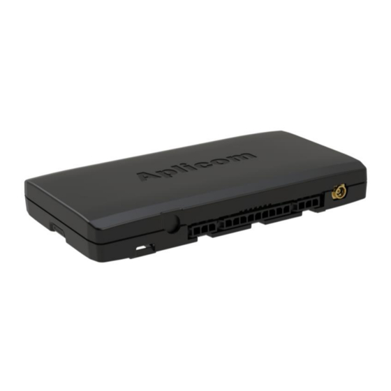
Order code K521000
Important:
Please read this installation guide before the installation.
Aplicom Oy, P.O. Box 33, FI-44101 Äänekoski, Finland, Telephone +358 10 841 9414
Business ID 0995791-7, Äänekoski
Info@aplicom.fi
www.aplicom.com
Advertisement
Table of Contents

Related Manuals for APLICOM A9 PRO


Summary of Contents for APLICOM A9 PRO
- Page 1 Installation Guide rev. 1.0.0 This guide supports following devices D108300 A9 PRO Order code K521000 Important: Please read this installation guide before the installation. Aplicom Oy, P.O. Box 33, FI-44101 Äänekoski, Finland, Telephone +358 10 841 9414 Business ID 0995791-7, Äänekoski Info@aplicom.fi www.aplicom.com...
-
Page 2: Package Content
6. Connect the vehicle power supply to A9 wiring power supply with fuse protection Insert the SIM card by opening the A9 PRO unit. Press locking lid on the other end of the device and at the same time lift up top case on locking side. Finally remove entire top case carefully and insert the SIM. - Page 3 GPRS and shouldn't be installed in metal cage. Unit's product label is installed under top cover. Note! Install the A9 PRO unit as far away as possible (minimum 1 metres recommended) from the car radio and its antenna or other electrical devices to avoid...
- Page 4 Figure 7. There are three mounting lugs on the sides of the A9 PRO device the bottom of A9 PRO device and other half firmly to the surface on which the cover. Install the A9 PRO device using these mounting lugs with the cable tie A.
- Page 5 Connect the cables to A9 PRO device and peripherals as advised in the connection guide. Figure 14. • Install the A9 PRO unit as far away as possible (minimum 1 metres recommended) from the car radio and its antenna or other electrical devices to avoid any interference.
- Page 6 Notice that the cable angle shouldn't be too tight. Figure 8. Figure 9. Figure 10. Connector sticker...
- Page 7 Pin 2, 1-Wire Data Pin 3, GND Figure 12 SW CFG Pin 1, A9 TxD Pin 2, A9 RxD Pin 3, GND Used to SW configuration, COM1 port (sw option) and SW debug. Figure 13 Note! Use only Aplicom specific cable.
-
Page 8: Testing Installation
Testing installation If the unit has a default configuration 1. Connect the power on. 2. Status led is red when the software is started (this takes about 30s). 3. Status led is green when GPS fix is received (this takes about another 30s). Now the unit is working correctly. If the unit has a service providers configuration follow their instruction, for example ensure that data is sended to the server. - Page 9 iButton 3PAD POTENTIOMETER Figure 14. Connection guide Note! If DIN1 is in IGN use then DIN2, DIN3 and GPIO are usable inputs.
-
Page 10: Technical Data
Technical Data 6,8…32Vdc (nominal +12Vdc) Supply voltage Dimensions 61mm (W) x 112mm (L) x 13mm (H) Current Typical: < 100mA Weight 70g with internal battery consumption Max (peak): 1A / < 1s GPS antenna 3Vdc Housing / material IP31, PC/ABS LG chem. power supply GN5001TF Fuse... - Page 11 • As a rule, when pulling Aplicom cables through inlets or tubes during installation, it is not allowed to pull directly from connectors. Instead the pull must be directed to cable itself. • The place of installation should be safe from detergents and corrosive substances.
-
Page 12: Installation Checklist
INSTALLATION CHECKLIST Action/Functionality DEVICE INSTALLATION The place of installation is safe from accidental knocks and excessive humidity. Device is fastened tightly and safely, with no possible interference with vehicle safety system like Airbag. etc. CABLES The cables are led carefully along a well-protected route to the device and the peripherals. All cables are correctly connected and secured with fuses. - Page 13 Printed in Finland. All rights reserved. Reproduction in whole or in part in any form is prohibited without the prior written consent of the copyright owner. Aplicom Oy makes every effort to ensure that the information in this manual is correct, but accepts no liability for any errors or omission.
Need help?
Do you have a question about the A9 PRO and is the answer not in the manual?
Questions and answers