Table of Contents
Advertisement
Quick Links
APLICOM A9 IPEX
Installation guide rev. 3.0.6
This guide supports following device
A9 IPEX
Document code K520010
Important:
Please read this installation guide before the installation.
Aplicom Oy, P.O. Box 33, FI-44101 Äänekoski, Finland, Telephone +358 10 841 9414
Business ID 0995791-7, Äänekoski
Info@aplicom.fi
www.aplicom.com
Advertisement
Table of Contents

Related Manuals for APLICOM A9 IPEX


Summary of Contents for APLICOM A9 IPEX
- Page 1 Installation guide rev. 3.0.6 This guide supports following device A9 IPEX Document code K520010 Important: Please read this installation guide before the installation. Aplicom Oy, P.O. Box 33, FI-44101 Äänekoski, Finland, Telephone +358 10 841 9414 Business ID 0995791-7, Äänekoski Info@aplicom.fi www.aplicom.com...
- Page 2 All rights reserved. Reproduction in whole or in part in any form is prohibited without the prior written consent of the copyright owner. Aplicom Oy makes every effort to ensure that the information in this manual is correct, but accepts no liability for any errors or omission.
-
Page 3: Package Content
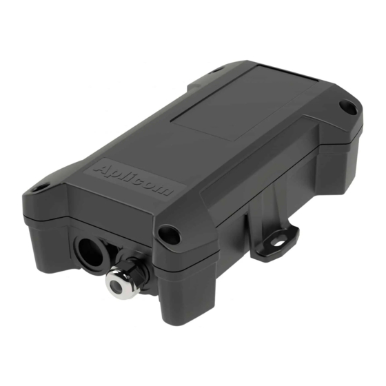
2. Install SIM card. Figure 2. 3. Connect internal battery connection. Figure 3. 4. Connect unit to external power source by using A9 IPEX cable or A9 NEX/TRIX power and IO cable (D337050). 5. Download your configuration to the unit by using A9 NEX/TRIX data cable D337055. Figure 4. - Page 4 Figure 5 Figure 4 Figure 6 Tighten opposite corner (Figure 6) and continue similarly with remaining two corners. Mechanical Installation Note that the unit includes internal GPRS and GPS antennas and shouldn’t be installed in metal cage!!! Because of the internal GPS/GLONASS antenna, install unit to place where unit´s top cover has the best possible open sky view.
-
Page 5: Electrical Installation
Protect power supply lines (6.8…32Vdc) with 3A fuse at power supply end of line. • Install the A9 IPEX unit as far away as possible (minimum 1 metres recommended) from the car radio and its antenna or other electrical devices to avoid any interference. - Page 6 • Install the A9 IPEX unit to a place where unit’s internal antennas have the best possible sky view for GPS/GLONASS satellites and the best possible visibility to GSM/GPRS/3G network base stations. • If the IGN –line is used ensure that it is connected to power line, in modern cars for example the lights etc.
-
Page 7: Technical Data
All signal inputs connected to A9 IPEX must be fuse protected, max 3A. • As a rule, when pulling Aplicom cables through inlets or tubes during installation, it is not allowed to pull directly from connectors. Instead the pull must be directed to cable itself. -
Page 8: Remarque Importante
or modifications not expressly approved by the party responsible for compliance could void the user’s authority to operate the equipment. Part §15.105(b) Class B device: Note: This equipment has been tested and found to comply with the limits for a Class B digital device, pursuant to part 15 of the FCC Rules. -
Page 9: Installation Checklist
ANTENNAS A9 IPEX unit is fitted in such a way that its visibility to base stations is as unobstructed as possible (vehicle roof; as far as possible away from other antennas, flashing lights etc.). A9 IPEX unit is fitted in such a way that its satellite visibility is as unobstructed as possible (vehicle roof;... -
Page 10: Cable Installation
APPENDIX: INSTALLATION GUIDE OF THE IPEX CABLE Cable installation At first, install cable glands body and seal to the housing. Seal is placed outside of the housing. Tighten the nut taking care that seal is firmly located under the gland. Note! All metal grit has to be removed from the housing using compressed air after the installation! Mount the cable to the gland so, that outer jacket of the cable can be seen inside the housing (refer to... - Page 11 Slide cable gland parts toward the gland with the help of the metal nut. Note, that the plastic tightening part has assembly direction tabs to fit correctly to the metal body. Tabs are shown with the red arrow in the picture below.
Need help?
Do you have a question about the A9 IPEX and is the answer not in the manual?
Questions and answers