Advertisement
Advertisement
Table of Contents

Summary of Contents for APLICOM A1
- Page 1 Installation guide rev. 3.1.0 Order code K503001 Important: Please read this installation guide before the installation. Aplicom Oy, P.O. Box 33, FI-44101 Äänekoski, Finland, Telephone +358 14 529 011, Fax +358 14 529 0190 Business ID 0995791-7, Äänekoski Info@aplicom.fi www.aplicom.com...
- Page 2 All rights reserved. Reproduction in whole or in part in any form is prohibited without the prior written consent of the copyright owner. Aplicom Oy makes every effort to ensure that the information in this manual is correct, but accepts no liability for any errors or omission.
-
Page 3: Mechanical Installation
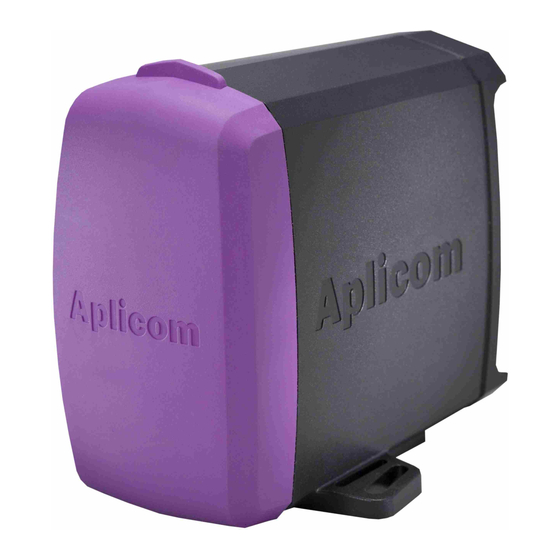
Select the place of installation from a safe, dry and mechanically protected area. Avoid installation to places of direct sunlight and extreme temperature. There are two mounting lugs on the sides of the A1 device cover. Install the A1 device using both of the mounting lugs in one of these ways (see figures below). -
Page 4: Electrical Installation
Protect power supply lines (6,8...32Vdc) with 3A (max 10A) fuse at power supply end of line. • Connect the cables to A1 device and peripherals as advised in the connection guide. Figure 11. IGN- line • must be always connected. -
Page 5: Technical Data
** = CAN bus is available in A1 FLEX and A1 MAX only *** = Available only when internal battery option included. +5V, 100mA output*, active when A1 is on, same supply for IO 1 and 2 (total 100mA max.) -
Page 6: Installation Checklist
It is recommended to use installation materials provided Installation Kit for A1 for installation. • As a rule, when pulling Aplicom cables through inlets or tubes during installation, it is not allowed to • pull directly from connectors. Instead the pull must be directed to cable itself. - Page 7 NOTE! This connection guide contains only example connections, not exact application specific connections. Figure 11. Connection guide...
- Page 8 Figure 12. SIM card and Internal battery installation. NOTE : Aplicom Oy recommends that the battery is changed after maximum three years use as a predictive service action. Aplicom Oy is not responsible of any loss of data, income or any consequential damage and repair costs, which might be caused by improper use of batteries.


Need help?
Do you have a question about the A1 and is the answer not in the manual?
Questions and answers