Advertisement
Quick Links
Little Giant
P . O. Box 12010
Oklahoma City, OK 73157-2010
405.947.2511 • Fax: 405.947.8720
www.LittleGiantPump.com
CustomerService-WTS@fele.com
INTRODUCTION
GB
This instruction sheet provides you with the information required
to safely own and operate your Little Giant product. Retain these
instructions for future reference.
The Little Giant product you have purchased is of the highest
quality workmanship and material, and has been engineered
to give you long and reliable service. Little Giant products are
carefully tested, inspected, and packaged to ensure safe delivery
and operation. Please examine your unit carefully to ensure that
no damage occurred during shipment. If damage has occurred,
please contact the place of purchase. They will assist you in
replacement or repair, if required.
READ
THESE
INSTRUCTIONS
ATTEMPTING
TO
INSTALL,
YOUR LITTLE GIANT PRODUCT. KNOW THE PRODUCT'S
APPLICATION, LIMITATIONS, AND POTENTIAL HAZARDS.
PROTECT YOURSELF AND OTHERS BY OBSERVING ALL
SAFETY INFORMATION. FAILURE TO COMPLY WITH THESE
INSTRUCTIONS COULD RESULT IN PERSONAL INJURY AND/
OR PROPERTY DAMAGE!
PRE-PACKAGED UNIT
Verify all parts with basin and cover assemblies are received intact (Figure 1).
The selected discharge and vent size will determine which flanges to use.
The flanges provided will allow the following vent/discharge combinations
to be used:
•
2" discharge/3" vent
•
3" discharge/2" vent
•
2" discharge/2" vent
•
3" discharge/3" vent
Figure 1.
Pre-Packaged
9S-SMPXC-LG
10S-SMPXC-LG
CAREFULLY
BEFORE
OPERATE,
OR
SERVICE
(OPTIONAL)
NOTE: The cover has three pre-fabricated holes, one to fit the 2-hole cord
grommet, one to fit the 2" flange, and one to fit the 3" flange or 3" to 2"
reducer flange (Figure 3). Remove proper flanges from the hardware kit to
accommodate the vent/discharge combination used.
1. Remove bolts and washers in cover and set aside.
2. Remove gasket material from hardware kit and place material around
circumference of basin inside of bolt circle.
3. Install the discharge pipe in the discharge of the pump.
4. Install float switch 9" from bottom of basin with a 3-1/2" tether length. Float
switch should be installed in a manner that will not allow it to contact the
pump or side of basin during operation. Refer to float switch instruction
manual for alternative settings. Place the pump in the basin.
5. Install the adapt-a-flex flange that fits the discharge on the underside
of the cover. Lube the adapt-a-flex flange and discharge pipe with
petroleum jelly or other type of lubricant. Route the power cord and float
switch cord through the smallest hole before installing cover. Slide the
cover with the adapt-a-flex flange in place over the discharge pipe.
6. Install the cord grommet by placing the power cord and float switch
cord in the grommet openings. Then push the grommet into the smallest
hole in the cover.
7. Install an adapt-a-flex flange in the remaining hole that corresponds to
the vent pipe size used. Lubricate the flange and vent pipe and press
the vent pipe into the flange 2 to 3 inches.
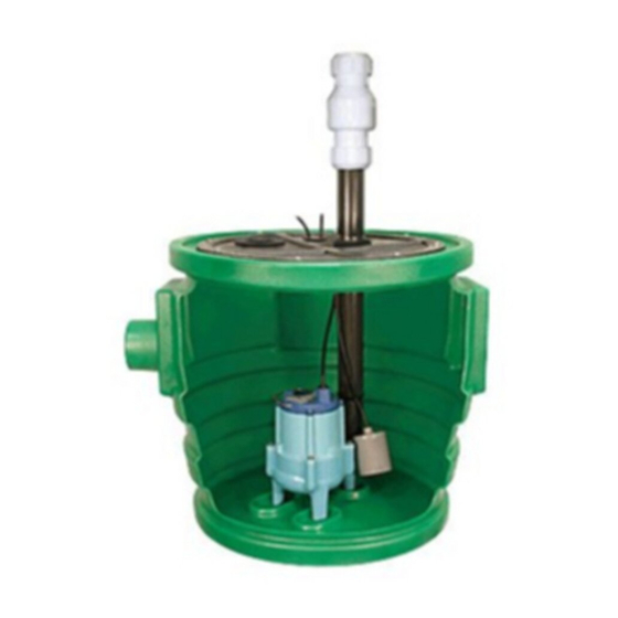
PRE-ASSEMBLED UNIT
The pre-assembled unit (Figure 2) is furnished fully assembled and ready
for installation. Remove check valve from discharge pipe and re-install as
shown on typical installation (Figure 3). CAUTION: For best performance of
check valves when handling solids, install in a horizontal position or at an
angle of not more than 45°. Do not install check valve in a vertical position
as solids may settle in valve and prevent opening on start-up. Remove the
cord from the vent hole and install the vent pipe in the hole with the adapt-
a-flex flange. (See Figure 3 to complete typical installation.)
To test the unit, plug the unit in and run water into the basin until the unit
switches on. If the unit does not operate, refer to the troubleshooting
information in the instructions for the pump.
Figure 2.
Pre-Assembled
1
Advertisement

Related Manuals for Little Giant 9S-SMPXC-LG


Summary of Contents for Little Giant 9S-SMPXC-LG
- Page 1 This instruction sheet provides you with the information required 5. Install the adapt-a-flex flange that fits the discharge on the underside to safely own and operate your Little Giant product. Retain these of the cover. Lube the adapt-a-flex flange and discharge pipe with instructions for future reference.
- Page 2 For technical assistance, please contact ....1.888.956.0000 www.LittleGiantPump.com CustomerService-WTS@fele.com Form 998362 - 07/2007 © 2007 Franklin Electric Co., Inc. Little Giant® is a registered trademark of Franklin Electric Co., Inc.