
Related Manuals for RIEKER Flex H6EX-A1


Summary of Contents for RIEKER Flex H6EX-A1
- Page 1 Inclinometers For Hazardous Locations Current 0..24mA Voltage 0..10V Digital RS485 Dual Axis Up to 360º Flex™ H6EX-A1 Installation Manual 2019...
-
Page 2: Table Of Contents
5: F ....................7 RONT URFACE ARKINGS FOR ERIAL UMBER IGURE 6: F ......................7 ACTORY ONFIGURED EFAULTS ABEL IGURE RIEKER INC • 34 MOUNT PLEASANT ROAD • ASTON • PA • 19014 • USA 610-500-2000 fax: 610-500-2002 support@riekerinc.com www.riekerinc.com... -
Page 3: Sensor Description
(current or voltage) output options available. Each output is linear with respect to the input angle directly. The digital RS485 output uses two-wire, half duplex communication, along with a Rieker specific protocol. This protocol can be used to measure the angle of both axes, as well as configure many of the parameters of the sensor. -
Page 4: Applicable Standards
47 CFR Ch. 1 – FCC Part 15 Class A – Radio Frequency Devices – Subpart B – Unintentional Radiators • ICES-003 – Issue 6 January 2016 Class A –Interference-Causing Equipment Standard – Digital Apparatus • RIEKER INC • 34 MOUNT PLEASANT ROAD • ASTON • PA • 19014 • USA 610-500-2000 fax: 610-500-2002 support@riekerinc.com... -
Page 5: H6Ex-A1 Instructions For Safety
The sensor is designed to measure dual-axis inclination and output an analog and/or digital signal. Assembling and Dismantling The H6EX-A1 shall not be serviced, dismantled, or re-assembled by the user. RIEKER INC • 34 MOUNT PLEASANT ROAD • ASTON • PA • 19014 • USA 610-500-2000 fax: 610-500-2002 support@riekerinc.com... -
Page 6: Maintenance
(bottom right of Figure 3), a clockwise rotation from the zero position is considered positive and a counter-clockwise rotation from the zero position is considered negative. RIEKER INC • 34 MOUNT PLEASANT ROAD • ASTON • PA • 19014 • USA 610-500-2000 fax: 610-500-2002 support@riekerinc.com... -
Page 7: Adjustment
No software adjustments of H6EX-A1 analog output parameters are permitted. Scaled analog parameters can only be factory-set and must be selected at time of purchase. RIEKER INC • 34 MOUNT PLEASANT ROAD • ASTON • PA • 19014 • USA 610-500-2000 fax: 610-500-2002 support@riekerinc.com... -
Page 8: Markings
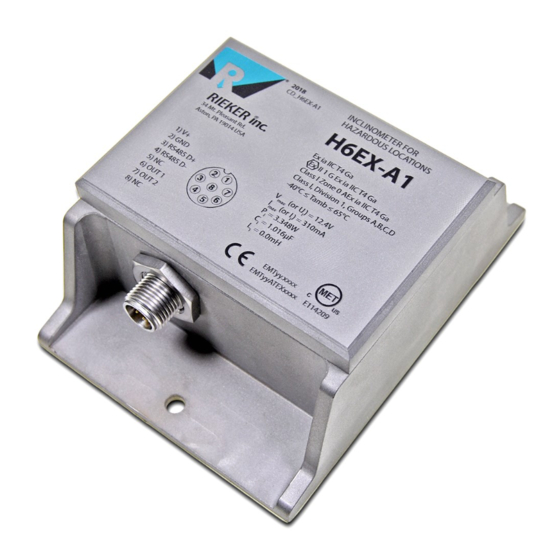
In addition, the factory defaults label, located on the box of the H6EX-A1 sensor, provides the configured analog output parameters. Factory Configured Defaults Label FIGURE 6: RIEKER INC • 34 MOUNT PLEASANT ROAD • ASTON • PA • 19014 • USA 610-500-2000 fax: 610-500-2002 support@riekerinc.com... -
Page 9: H6Ex-A1 Connector Wiring Tables
NOTE: The H6EX-A1 Sensor’s Chassis Ground is NOT the same as the signal ground for the current output return. The analog output return must be connected to the POWER/SIGNAL COMMON (pin 2). RIEKER INC • 34 MOUNT PLEASANT ROAD • ASTON • PA • 19014 • USA 610-500-2000 fax: 610-500-2002 support@riekerinc.com...
Need help?
Do you have a question about the Flex H6EX-A1 and is the answer not in the manual?
Questions and answers