
Related Manuals for RIEKER Flex MPI Series


Summary of Contents for RIEKER Flex MPI Series
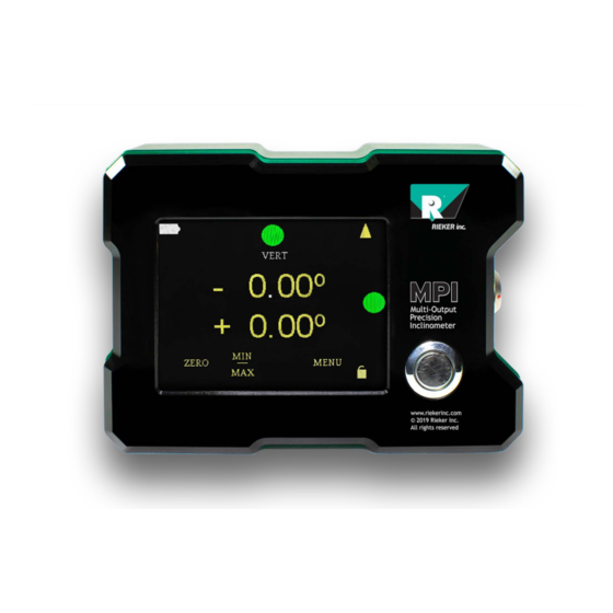
- Page 1 Multi-Output Precision Inclinometer Touch Screen User Programmable Dual & Single Axis Multi-Mount Flex Series MPI User Guide 2021...
-
Page 2: Product Safety Guide For Rieker Mpi Digital Graphic Display
The Rieker MPI device is NOT rated for hazardous locations. When you are in such an area, turn off the device, and do not remove or install battery chargers, AC adapters, or any other accessory. In such areas, sparks can occur and cause an explosion or fire. -
Page 3: Table Of Contents
RS485 Bus Wiring Configurations ................23 Wiring for the Relay Outputs .................. 24 Digital RS485 Communications ................. 25 RS485 Protocol ...................... 25 RIEKER INC • 34 MOUNT PLEASANT ROAD • ASTON • PA • 19014 • USA 610-500-2000 support@riekerinc.com fax: 610-500-2002... - Page 4 MPI User Guide Page 3 of 28 Packet Format ....................25 RS485 Command Functions .................. 26 Function Descriptions ..................27 RIEKER INC • 34 MOUNT PLEASANT ROAD • ASTON • PA • 19014 • USA 610-500-2000 support@riekerinc.com fax: 610-500-2002 www.riekerinc.com...
- Page 5 EVISION ISTORY 2: HS2P9 26 9- ..................23 ABLE NPUT OUTPUT ONNECTOR IRING 3: RS485 F ..........................26 ABLE UNCTION RIEKER INC • 34 MOUNT PLEASANT ROAD • ASTON • PA • 19014 • USA 610-500-2000 support@riekerinc.com fax: 610-500-2002 www.riekerinc.com...
-
Page 6: Updates & Revision History
The information in this guide may be subject to change. Please visit www.riekerinc.com for latest version of this document. TABLE 1: REVISION HISTORY DATE DESCRIPTION 12/24/19 Initial Release RIEKER INC • 34 MOUNT PLEASANT ROAD • ASTON • PA • 19014 • USA 610-500-2000 support@riekerinc.com fax: 610-500-2002 www.riekerinc.com... -
Page 7: Mpi Installation
Figure the right. • The top line of the display is the X-Axis measurement. Looking at the display with the connector RIEKER INC • 34 MOUNT PLEASANT ROAD • ASTON • PA • 19014 • USA 610-500-2000 support@riekerinc.com fax: 610-500-2002... -
Page 8: Main Screen Adjustments
X axis will be displayed in the center of the screen. To set the device back to dual axis indication touch the screen just above the displayed X axis indication. The dual axis will again be displayed. RIEKER INC • 34 MOUNT PLEASANT ROAD • ASTON • PA • 19014 • USA 610-500-2000 support@riekerinc.com fax: 610-500-2002 www.riekerinc.com... -
Page 9: Zero The Display Indication
MIN/MAX indicator is touched on the main screen. If a Single axis is selected only that axis’s MIN and MAX angles will be displayed. RIEKER INC • 34 MOUNT PLEASANT ROAD • ASTON • PA • 19014 • USA 610-500-2000 support@riekerinc.com... -
Page 10: Battery Charge Level Indicator
Arrows are used to navigate through the adjustment screens and to set parameters. RIEKER INC • 34 MOUNT PLEASANT ROAD • ASTON • PA • 19014 • USA 610-500-2000 support@riekerinc.com... -
Page 11: Rules For The Arrows
RS232 • Output enable/disable Baud Rate adjust RS485 • Output enable/disable Baud Rate adjust Switches • Multiple Relay output enable/disable RIEKER INC • 34 MOUNT PLEASANT ROAD • ASTON • PA • 19014 • USA 610-500-2000 support@riekerinc.com fax: 610-500-2002 www.riekerinc.com... -
Page 12: Display Adjustments
• resolution settings. 0.01, 0.1, 1 When finished, touch the left-facing arrow to return to the DISPLAY ADJUST Menu. • RIEKER INC • 34 MOUNT PLEASANT ROAD • ASTON • PA • 19014 • USA 610-500-2000 support@riekerinc.com fax: 610-500-2002 www.riekerinc.com... -
Page 13: Display Adjust Menu 2
Touch “MENU” on the main screen, which brings up the OUTPUT MENU. • Then touch the arrow to the right of “DISPLAY” to bring up the DISPLAY ADJUST Menu. • RIEKER INC • 34 MOUNT PLEASANT ROAD • ASTON • PA • 19014 • USA 610-500-2000 support@riekerinc.com fax: 610-500-2002... - Page 14 • The current setting “OFF” will be displayed. Touch the up-facing or down-facing arrow to • toggle between “ON” and “OFF”. RIEKER INC • 34 MOUNT PLEASANT ROAD • ASTON • PA • 19014 • USA 610-500-2000 support@riekerinc.com fax: 610-500-2002...
-
Page 15: Analog Output
• Touch the up- and down-facing arrows to select the MINIMUM RANGE (+Y) angle for • the X axis analog output. RIEKER INC • 34 MOUNT PLEASANT ROAD • ASTON • PA • 19014 • USA 610-500-2000 support@riekerinc.com fax: 610-500-2002... -
Page 16: Rs232 Output
Touch the up- and down-facing arrows to select the BAUD RATE. • Baud Rate selections: 9.6K, 19.2K, 38.4K, 65.2K, 115.2K, 125K, 128K, 250K RIEKER INC • 34 MOUNT PLEASANT ROAD • ASTON • PA • 19014 • USA 610-500-2000 support@riekerinc.com fax: 610-500-2002 www.riekerinc.com... -
Page 17: Switches
Touch the Menu indicator on the main screen; then touch the arrow next to the OUTPUT MENU item SWITCHES HORZ to enter the LED ADJUST HORZ adjustment screen. If the item is SWITCH VERT RIEKER INC • 34 MOUNT PLEASANT ROAD • ASTON • PA • 19014 • USA 610-500-2000 support@riekerinc.com... - Page 18 When finished, touch the arrow in the lower right corner to proceed to the next adjustment. RIEKER INC • 34 MOUNT PLEASANT ROAD • ASTON • PA • 19014 • USA 610-500-2000 support@riekerinc.com...
- Page 19 OPEN or CLOSED state. When finished, touch the arrow in the lower right corner to proceed to the next adjustment. SWITCH ADJUST DELAY to proceed to the next adjustment. SWITCH ADJUST DELAY RIEKER INC • 34 MOUNT PLEASANT ROAD • ASTON • PA • 19014 • USA 610-500-2000 support@riekerinc.com fax: 610-500-2002 www.riekerinc.com...
-
Page 20: Figure 3. Switch Wiring Diagram
0 to 30 VDC 500 mA Relay 4 SW4 OUT 0 to 30 VDC 500 mA FIGURE 3. SWITCH WIRING DIAGRAM RIEKER INC • 34 MOUNT PLEASANT ROAD • ASTON • PA • 19014 • USA 610-500-2000 support@riekerinc.com fax: 610-500-2002 www.riekerinc.com... - Page 21 YEL to RED, Y AXIS, SW1 and the current trip angle will be displayed. Use the up and down arrows to set the desired yellow to red negative transition angle. When finished, touch the arrow in the lower RIEKER INC • 34 MOUNT PLEASANT ROAD • ASTON • PA • 19014 • USA 610-500-2000 support@riekerinc.com...
- Page 22 SWT, DELAY, and the current delay time will be displayed. Use the up and down arrows to set the delay time. When finished, touch the arrow in the lower right corner to return to the OUTPUT MENU and then the main menu. RIEKER INC • 34 MOUNT PLEASANT ROAD • ASTON • PA • 19014 • USA 610-500-2000 support@riekerinc.com fax: 610-500-2002 www.riekerinc.com...
-
Page 23: Sensitivity & Zero Angle Calculation (Voltage Outputs Only)
Zero Degree Angle Output = 0���� + ��0° − ( −30° ) � ∗ 0.040 ���� ° � � = 1.2���� RIEKER INC • 34 MOUNT PLEASANT ROAD • ASTON • PA • 19014 • USA 610-500-2000 support@riekerinc.com fax: 610-500-2002 www.riekerinc.com... -
Page 24: Wiring Diagrams And Connection Procedures
When using the digital output, the MPI can be connected to a bus configuration. USB to RS485 120Ω Termination required at ends of bus FIGURE 4: RS485 TO BUS CONNECTION RIEKER INC • 34 MOUNT PLEASANT ROAD • ASTON • PA • 19014 • USA 610-500-2000 support@riekerinc.com fax: 610-500-2002 www.riekerinc.com... -
Page 25: Wiring For The Relay Outputs
PLC, etc. Relay Out 4 PIN 4 Digital Multimeter, PLC, etc. Digital Multimeter, PLC, etc. Digital Multimeter, HS2P9F26 Connector PLC, etc. RIEKER INC • 34 MOUNT PLEASANT ROAD • ASTON • PA • 19014 • USA 610-500-2000 support@riekerinc.com fax: 610-500-2002 www.riekerinc.com... -
Page 26: Digital Rs485 Communications
0000 4040 ABCD A5BE 123456 FB36 9876543210 E86E For more information on the CRC and for a calculator visit: http://www.lammertbies.nl/comm/info/crc-calculation.html RIEKER INC • 34 MOUNT PLEASANT ROAD • ASTON • PA • 19014 • USA 610-500-2000 support@riekerinc.com fax: 610-500-2002 www.riekerinc.com... -
Page 27: Table 3: Rs485 Function
Get Address Returns the sensor address Get Angle Returns the angle Change Lock Change lock level to 0 or 1 RIEKER INC • 34 MOUNT PLEASANT ROAD • ASTON • PA • 19014 • USA 610-500-2000 support@riekerinc.com fax: 610-500-2002 www.riekerinc.com... - Page 28 Get address of sensor (broadcast command) Received Command: 0000 00E1 0003 00E1 7D76 [DEST] [SRC] [FUNCT] [DL] [DATA] [CRC] Sensor address is 225 (0x00E1) RIEKER INC • 34 MOUNT PLEASANT ROAD • ASTON • PA • 19014 • USA 610-500-2000 support@riekerinc.com fax: 610-500-2002 www.riekerinc.com...
- Page 29 [DEST] [SRC] [FUNCT] [DL] [DATA] [CRC] Change lock level to 1 Received Command: 0000 00E1 0000 CC1E [DEST] [SRC] [FUNCT] [DL] [DATA] [CRC] RIEKER INC • 34 MOUNT PLEASANT ROAD • ASTON • PA • 19014 • USA 610-500-2000 support@riekerinc.com fax: 610-500-2002 www.riekerinc.com...
Need help?
Do you have a question about the Flex MPI Series and is the answer not in the manual?
Questions and answers