Vestil STOR-96-G-W-1RH Owner's Manual
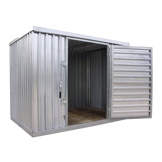
Storage shed
Hide thumbs
Also See for STOR-96-G-W-1RH:
- Owner's manual (20 pages) ,
- Owner's manual (19 pages) ,
- Manual (22 pages)
Advertisement
Quick Links
STOR-96 and 912-G-W-1RH
V
ESTIL
2999 N. Wayne St., Angola, IN 46703
Ph: 260-665-7586 · Fax: 260-665-1339
E-mail: info@vestil.com · Website: www.vestil.com
S
S
TORAGE
HED MODELS
Introduction............................ ...................... 1
Assembly Instructions STOR-96-G-W-1RH......... 2-5
Assembly Instructions STOR-912-G-W-1RH......... 6-12
I
N
, W
MPORTANT
OTES
Ensure that all employees understand and follow these instructions.
Failure to read and understand this owner's manual before using or
servicing constitutes a misuse of the product. All persons who will
install, use, or care for this product must be familiar with this material.
Ensure that all information / safety / warning labels stay in place and are
o
legible.
Do not perform any modifications to the unit without the manufacturer's
approval. Failure to receive authorization for changes to the equipment
could void the warranty.
Maintenance and repairs are to be done only by personnel qualified to
perform the required work. Consideration will not be given for warranty
repair charges without prior written authorization by the manufacturer.
STOR-96-G-W-1RH
STOR-912-G-W-1RH
Copyright 2016 Vestil Mfg. Co.
M
C
ANUFACTURING
ORP
: STOR-96-G-W-1RH & STOR-912-G-W-1RH
S
I
ARNINGS AND
AFETY
1217
.
STOR-96-G-W-1RH Exploded Parts Diagram & parts List.......... 13
STOR-912-G-W-1RH Exploded Parts Diagram & Parts List........... 14
Limited warranty....................................................................................... 15
NSTRUCTIONS
O
'
WNER
M
ANUAL
R
I
ECEIVING
NSTRUCTIONS
It is possible that this product
could
incur
damage
transit.
Inspect the unit closely when
it arrives. If you see evidence
of damage or rough handling to
either the packaging or to the
product
when
it
is
unloaded, immediately make a
note of it on the Bill Of Lading!
It
is
important
that
remove the product's packaging
upon its arrival to ensure that
there is no concealed damage
or to enable a timely claim with
the carrier for freight damage.
Also verify that the product
and its specifications are as
ordered.
T
R
OOLS
EQUIRED
-7/16" socket or wrench
-1/2" socket or wrench
-5/16" nut driver for drill
-Level
-Eye/Hand protection advised
Note – At least two people
required
to
assemble
product; three suggested
Page 1 of 15
S
during
being
you
this
Advertisement

Related Manuals for Vestil STOR-96-G-W-1RH

Summary of Contents for Vestil STOR-96-G-W-1RH
- Page 1 E-mail: info@vestil.com · Website: www.vestil.com : STOR-96-G-W-1RH & STOR-912-G-W-1RH TORAGE HED MODELS Introduction………………………. ……………….… 1 STOR-96-G-W-1RH Exploded Parts Diagram & parts List….…… 13 STOR-912-G-W-1RH Exploded Parts Diagram & Parts List……..14 Assembly Instructions STOR-96-G-W-1RH.…….. 2-5 Assembly Instructions STOR-912-G-W-1RH…...… 6-12 Limited warranty..................15...
- Page 2 Consult the factory in the event there are any questions or problems at the time of installation, or for information regarding optional features not covered by the owner’s manual. --------------------------------------------------------------------------------------- STOR-96-G-W-1RH INGLE TORAGE NIT MODEL Place wooden floor on clean and level surface. Position back wall as shown above. Page 2 of 15 Copyright 2016 Vestil Mfg. Co.
- Page 3 Lock strip Install lockstrip to both vertical ends of back wall. Install one side wall by inserting into the lockstrip just installed on the back wall vertical end. Page 3 of 15 Copyright 2016 Vestil Mfg. Co.
- Page 4 Install lockstrips (2) on side walls; then insert front wall with door assembly into lockstrips (door not shown in photo above). Install lag bolts, ¼” X 2” lag bolts, utilizing the 5 predrilled holes to secure front wall to the wooden floor. Page 4 of 15 Copyright 2016 Vestil Mfg. Co.
- Page 5 Secure roof to the front and back walls with 8pc 1” long self-tapping screws. (4 pcs. per wall) These holes are not predrilled. Space screws evenly across both walls. Fully assembled STOR-96-G-W-1RH Page 5 of 15 Copyright 2016 Vestil Mfg. Co.
- Page 6 Place wooden floors with 2”X4” joints together on a level surface and position pre-cut spacers as shown. Using 20pc of 2” long wood screws fasten down the spacer strips directly over the 2”X4” joints. Evenly space wood screws along entire length of spacer strip. Page 6 of 15 Copyright 2016 Vestil Mfg. Co.
- Page 7 Install Face Joint to the center fo the two joined wooden floors using 2pc of ¼” X 2” lag bolts – one bolt per face joint on each side for the wooden floors. Begin assembly with wooden floors on clean level surface. Position back wall as shown above. Page 7 of 15 Copyright 2016 Vestil Mfg. Co.
- Page 8 Lock strip Install lockstrip to both vertical ends of back wall. Install one side wall by inserting into the lockstrip just installed on the back wall vertical end. Page 8 of 15 Copyright 2016 Vestil Mfg. Co.
- Page 9 Secure both side walls to the wooden floor using ¼” X 2” lag bolts into the 5 predrilled holes on each side. Install lockstrip on end of side wall and then install Side Fill Panel, as seen above on right hand side (see step 13 for installation) Page 9 of 15 Copyright 2016 Vestil Mfg. Co.
- Page 10 Install lockstrips (2) on each side wall; then insert front wall with door assembly into lockstrips (door not shown in photo above). Install 5pc of ¼”X2”lag bolts into predrilled holes to secure front wall to the wooden floor. Page 10 of 15 Copyright 2016 Vestil Mfg. Co.
- Page 11 Secure the roof seam cover plate to roof and walls with 4 self-tapping screws. (2 screws at each end of the cover plate) Page 11 of 15 Copyright 2016 Vestil Mfg. Co.
- Page 12 Secure roof to front and back walls with 16pc 1” long self-tapping screws.(4pc per wall) These holes are not predrilled. Space screws evenly. Step 20 The assembly process is now finished: Fully assembled STOR-912-G-W-1RH Page 12 of 15 Copyright 2016 Vestil Mfg. Co.
- Page 13 41-514-017 Weldment, side wall subassembly 41-514-013 Weldment, back wall subassembly 41-514-014 Weldment, roof wall subassembly 41-514-016 Assembly, front wall 41-514-048 Lock strip 41-037-003 22061 Bolt, lag bolt 31806 Screw, self-tapping screw Page 13 of 15 Copyright 2016 Vestil Mfg. Co.
- Page 14 Frame, roof seam angle, formed Frame, roof seam cover plate, formed 41-014-026 Lock, corner lock strip, formed 41-037-003 22061 ¼ in. x 2 in. zinc-plated hex lag bolt 31806 Screw, self-tapping screw 22061 Page 14 of 15 Copyright 2016 Vestil Mfg. Co.
- Page 15 The warranty period for original dynamic components is 90 days. For wearing parts, the warranty period is 90 days. The warranty periods begin on the date when Vestil ships the product to the warrantee. If the product was purchased from an authorized distributor, the periods begin when the distributor ships the product.
Need help?
Do you have a question about the STOR-96-G-W-1RH and is the answer not in the manual?
Questions and answers