
Related Manuals for Vanguard PCI-600


Summary of Contents for Vanguard PCI-600
- Page 1 PCI-600 PRIMARY CURRENT INJECTION DEVICE USER’S MANUAL Vanguard Instruments Company, Inc. 1520 S. Hellman Ave. Ontario, California 91761, USA TEL: (909) 923-9390 June 2013 FAX: (909) 923-9391 Revision 2...
- Page 2 Any deviation from the procedures described in this User’s Manual may create one or more safety hazards, may damage the PCI-600, or cause errors in the test results. Vanguard Instruments Company, Inc. assumes no liability for unsafe or improper use of the PCI-600.
-
Page 3: Table Of Contents
2.2.2. Measuring Current Transformer Primary and Secondary Currents ......11 LIST OF TABLES Table 1. PCI-600 Technical Specifications ..................3 Table 2. Functional Descriptions of PCI-600 Controls and Indicators ..........5 Table 3. Current Output vs. Time ....................6 LIST OF FIGURES... -
Page 4: Conventions Used In This Document
PCI-600 USER’S MANUAL REV 2 CONVENTIONS USED IN THIS DOCUMENT This document uses the following conventions: A key, switch, input, or knob on the PCI-600 is indicated as [KEY], [SWITCH], [INPUT], • [KNOB] Menu options are referenced as (MENU OPTION). -
Page 5: Introduction
AC. The timer stops when the PCI-600 input detects a change in the dry contact or voltage input, or detects the removal of the test current. The test results are then displayed in milli-seconds and fractions of a cycle(s) on the unit’s back-lit LCD screen (20 characters by 4 lines). -
Page 6: Pci-600 Technical Specifications
PCI-600 USER’S MANUAL REV 2 PCI-600 Technical Specifications Table 1. PCI-600 Technical Specifications TYPE 100 - 600 Amp current source PHYSICAL SPECIFICATIONS Dimensions: 17”W x 12.5”H x 10.5”D (42.6 cm x 32.0 cm x 27.0 cm); Weight: 46 lbs (21 kg) INPUT POWER 100 –... -
Page 7: Controls And Indicators
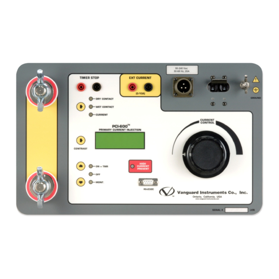
PCI-600 USER’S MANUAL Controls and Indicators The PCI-600’s controls and indicators are shown in Figure 1. A leader line with an index number points to each control and indicator, which is cross-referenced to a functional description in Table 2. The table describes the function of each item on the control panel. The purpose of the controls and indicators may seem obvious, but users should become familiar with them before using the PCI-600. -
Page 8: Table 2. Functional Descriptions Of Pci-600 Controls And Indicators
CURRENT TIMER STOP Timer "STOP" input connectors EXT CURRENT External current input connectors Input power connector Circuit Breaker/Power Switch PCI-600 ground stud. Connect ground stud to substation ground using provided GROUND cable. CURRENT Current control knob CONTROL RS-232C RS-232C port for factory calibration, diagnostics, and firmware updates... -
Page 9: Operating Procedures
[↑] [↓] keys. Three control modes are available: ON + TMR This mode turns on the PCI-600's current source and timer. This initiates a test and is stopped by using the "Timer Stop" inputs. The test results will be displayed on the LCD. The test can be terminated by pressing the key. -
Page 10: Timer Stop Input And Control
PCI-600 USER’S MANUAL REV 2 2.1.3. Timer Stop Input and Control After a test is started, the PCI-600 timer can be stopped and the current source turned off using one of three options listed below. Press the key next to the option LED indicators to [→]... -
Page 11: External Current Input
AC current. This current input is isolated. A typical application for this feature is to measure a Current Transformer (CT) current ratio. The user can set the PCI-600 to output a current through the CT primary input. The CT secondary output is measured with the PCI-600 “EXT CURRENT”... -
Page 12: Performing Tests
PCI-600 USER’S MANUAL REV 2 Performing Tests 2.2.1. Testing the Open Time Delay of a Protection Relay Follow the steps below to test the Open Time Delay of a protection relay: a. Make cable connections per the illustration below: b. Turn the knob counter-clockwise to the zero position. - Page 13 Press the [↑] key to select "ON + TMR" mode and start the test: i. The PCI-600 will inject the preset current into the bus and turn on the timer. The LCD will be updated as shown below: 986mS 59.2CY...
-
Page 14: Measuring Current Transformer Primary And Secondary Currents
PCI-600 USER’S MANUAL REV 2 2.2.2. Measuring Current Transformer Primary and Secondary Currents Follow the steps below to measure current transformer primary and secondary currents: a. Make cable connections per the illustration below: b. Turn the knob counter-clockwise to the zero position. - Page 15 Ext I: -1.004 A Drv I: 20.28 A The External current polarity is shown either as in-phase (“+” sign) or out of phase (“-” sign) with respect to the PCI-600's drive current. NOTE i. Turn off the current source by pressing the key.
- Page 16 1520 S. Hellman Ave • Ontario, CA 91761 • USA Phone: 909-923-9390 • Fax: 909-923-9391 www.vanguard-instruments.com Copyright © 2013 by Vanguard Instruments Company, Inc. PCI-600 User’s Manual • Revision 2 • June 28, 2013 • TA...
Need help?
Do you have a question about the PCI-600 and is the answer not in the manual?
Questions and answers