Table of Contents
Troubleshooting

Related Manuals for Vanguard EZCT-2KA


Summary of Contents for Vanguard EZCT-2KA
- Page 1 EZCT-2KA DIGITAL CURRENT-TRANSFORMER TESTER USER’S MANUAL Vanguard Instruments Company, Inc. 1520 S. Hellman Ave. Ontario, California 91761, USA TEL: (909) 923-9390 November 2016 FAX: (909) 923-9391 Revision 1.1...
- Page 2 Operating Voltage: The EZCT-2KA is rated for use with an operating voltage of 120V or 240V (factory pre-set) ±10% of selected voltage. Power Cord: The EZCT-2KA is supplied with a 16 AWG, 16A power cord with a NEMA 5-15P plug. A replacement cable must have the same or better rating and is available through the manufacturer.
-
Page 3: Table Of Contents
Restoring and Printing a Test Record From a USB Flash Drive ......31 3.4.3. Printing a Restored Test Record ................33 3.4.4. Printing a Directory of Test Records Stored in the EZCT-2KA’s Memory ....35 3.4.5. Printing a Directory of Test Records Stored in a USB Flash Drive ......38 3.4.6. - Page 4 LIST OF FIGURES Figure 1. EZCT-2KA Controls and Indicators ................... 6 Figure 2. Typical EZCT-2KA Excitation and Ratio Test Cable Connection ........10 Figure 3. Bushing CT Connection on Delta Transformer .............. 11 Figure 4. Bushing CT Connection on Y Transformer ..............11 Figure 5.
- Page 5 REV 1.0 EZCT-2KA USER’S MANUAL Figure 25 ............................98 Figure 26 ............................99 Figure 27 ............................. 100 Figure 28 ............................. 101 Figure 29 ............................. 102 Figure 30 ............................. 103 Figure 31 ............................. 103...
-
Page 6: Conventions Used In This Document
REV 1.0 EZCT-2KA USER’S MA NUAL CONVENT TIONS US SED IN TH HIS DOCU UMENT This docu ument uses the followin ng conventio ons: A key y or switch o on the EZCT- 2KA is indica ated as • [KEY... -
Page 7: Introduction
The EZCT-2KA automatically demagnetizes the CT under test when performing an excitation test. CT Winding Resistance Test The EZCT-2KA can also measure the DC resistance of the CT winding under test. The DC winding resistance measuring range is from 100 micro-ohms to 20 ohms. User Interface The EZCT-2KA features a back-lit LCD screen (240 x 128 pixels) that is viewable in both bright sunlight and low-light levels. - Page 8 Internal Test Plan Storage The EZCT-2KA can store up to 128 CT test plans in Flash EEPROM. A test plan defines the excitation test voltage and current range selection, CT nameplate ratio, and CT winding terminals (X1 to X5) for each of the tests.
-
Page 9: Furnished Accessories
EZCT-2KA USER’S MANUAL REV 1.0 Furnished Accessories The EZCT-2KA comes furnished with the following: • One 20' (6.1 m) X cable set (P/N 8000-0108) • One 35' (10.69 m) H cable set (P/N 8000-0157) • One power and ground combination cable (P/N 8000-0016) •... -
Page 10: Technical Specifications
REV 1.0 EZCT-2KA USER’S MA NUAL Technical S Specificatio Table 1. EZCT-2KA A Technical S Specification Portable curr rent-transforme er test set TYPE Dimensions : 17”W x 12.5” H x 12”D (42.7 7 cm x 32.0 cm x 26.9 cm) -
Page 11: Ezct-2Ka Controls And Indicators
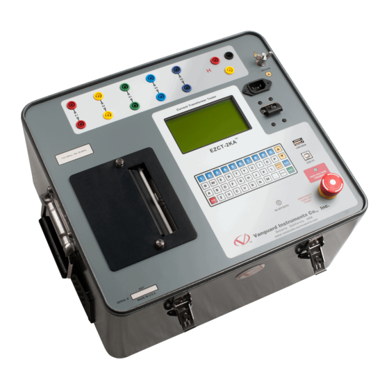
EZCT-2KA USER’S MANUAL REV 1.0 EZCT-2KA Controls and Indicators The EZCT-2KA’s controls and indicators are shown in Figure 1 below. A leader line with an index number points to each control and indicator, which is cross-referenced to a functional description in Table 2. The table describes the function of each item on the control panel. The purpose of the controls and indicators may seem obvious, but users should become familiar with them before using the EZCT-2KA. -
Page 12: Table 2. Functional Descriptions Of Ezct-2Ka Controls And Indicators
Functional Description Number Current transformer excitation voltage connectors. Each set of connectors contains a test voltage connector and sensing connector. The EZCT-2KA’s X X1, X2, X3, X4, X5 output terminals are rated to 2000 Vac working voltage. Any voltage above 2000 Vac will damage the input circuitry. -
Page 13: Pre-Test Setup
EZCT-2KA USER’S MANUAL REV 1.0 PRE-TEST SETUP Operating Voltages The EZCT-2KA’s operating voltage is preset at the factory for 100-120 Vac, 50/60 Hz or 200-240 Vac, 50/60 Hz. LCD Screen Contrast Control To increase the LCD screen contrast, press and hold the key for two seconds. - Page 14 REV 1.0 EZCT-2KA USER’S MA NUAL Replacing t the Therma al Printer P Paper The roll o of thermal p aper is hous sed inside a dispenser un nderneath t he printer co over. To rep lace the pape er, follow the e steps below •...
-
Page 15: Operating Procedures
Always connect the EZCT-2KA to the substation ground before connecting any test cables. The EZCT-2KA is supplied with one 20-foot X cable set and one 35-foot H cable. The X cable connections are required to run the current transformer excitation test. The H and X cable connections are required to run the transformer turns-ratio test. -
Page 16: Figure 3. Bushing Ct Connection On Delta Transformer
REV 1.0 EZCT-2KA USER’S MANUAL Figure 3. Bushing CT Connection on Delta Transformer Figure 4. Bushing CT Connection on Y Transformer... -
Page 17: Ezct-2Ka X Input Voltage Warning
300 Vac is applied to the X1-X2 terminals, a voltage of 2,364 Vac (300 Vac x 7.88) will be induced at the X1-X4 terminals. If all the test leads are connected to the EZCT-2KA and the excitation test is performed on the X1-X2 terminals, the voltage induced at the X1-X4 terminals will exceed 2,000 Vac as the voltage across the X1-X2 terminals increases above 250 Vac. -
Page 18: Performing Tests
REV 1.0 EZCT-2KA USER’S MANUAL Performing Tests 3.3.1. Entering Test Record Header Information You can enter the test record header information before performing tests. The record header includes identifying information such as the company, station, circuit, model number, etc. Once the header information has been entered, it will apply to all subsequent test records. - Page 19 EZCT-2KA USER’S MANUAL REV 1.0 d. The following screen will be displayed: STATION: ↑↓ TO POSITION "ENTER" TO ACCEPT Type the station name using the keypad and then press the key. [ENTER] e. The following screen will be displayed: CIRCUIT: ↑↓...
- Page 20 REV 1.0 EZCT-2KA USER’S MANUAL h. The following screen will be displayed: SERIAL NUMBER: ↑↓ TO POSITION "ENTER" TO ACCEPT Type the serial number using the keypad and then press the key. [ENTER] i. The following screen will be displayed: COMMENTS: ↑↓...
-
Page 21: Performing Resistance, Excitation, And Ratio Tests
The following procedure describes the general steps for performing excitation, resistance, and ratio tests. a. When the EZCT-2KA is turned on, it will first go through a start-up cycle and load the firmware. Then the “START-UP” menu will be displayed as shown below: 04/19/16 1.RUN TEST... - Page 22 REV 1.0 EZCT-2KA USER’S MA NUAL d. If f the selected d test includ ded an excita ation test, th he following screen will be displayed SELECT V VOLTAGE R RANGE: 1. 50V 2. 300V 3. 500V 4. 1200V 5. 2000V...
- Page 23 EZCT-2KA USER’S MANUAL REV 1.0 ENTER PLATE RATIO: Type the first number using the keypad. You can press the key to restart a field entry if necessary. [CLEAR] Press the key. The following screen will be displayed: [ENTER] ENTER PLATE RATIO: 1000 : 0.0...
- Page 24 REV 1.0 EZCT-2KA USER’S MANUAL h. The following screen will be displayed if the selected test included a resistance test: CALC ERR VS BURDEN? 1. YES 2. NO Press the key (YES). Selecting this option will print the current ratio error table as part of the tabulated test results.
- Page 25 EZCT-2KA A USER’S MA ANUAL RE V 1.0 l. T he following g screen will be displaye d showing a a summary o of the test pa arameters: TEST 1 P PARAMETER 500V 1.0A "ST TART" TO BEGIN ress the...
- Page 26 (YES) if you would like to print the test results. The test results will be printed on the thermal printer. A typical EZCT-2KA tabulated test report printout is shown in Figure 6. Typical graphic reports are shown in Figure 7 and Figure 8.
- Page 27 EZCT-2KA USER’S MANUAL REV 1.0 q. The following screen will be displayed: TEST 1 SAVED Press any key to continue. r. The following screen will be displayed: RUN ANOTHER TEST? 1. YES 2. NO Press the key (NO). s. The following screen will be displayed: SAVE THIS RECORD? 1.
- Page 28 BER 001 AS BEEN S SAVED! e test record d number is automatical lly assigned t to each test record stored in e EZCT-2KA’s s Flash EEPR NOTE ress any key y to return to o the “START T-UP” menu...
-
Page 29: Figure 6. Typical Ezct-2Ka Tabulated Report Printout
EZCT-2KA USER’S MANUAL REV 1.0 Figure 6. Typical EZCT-2KA Tabulated Report Printout... -
Page 30: Table 3. Descriptions Of Tabulated Test Results Elements
Number Test record header information. The EZCT-2KA X terminals (taps) that were selected for this test. Test note for this particular test. The test note can be up to 20-characters long. Recorded excitation current readings on the CT secondary winding. -
Page 31: Figure 7. Typical Ezct-2Ka Graphic Report
EZCT-2KA USER’S MANUAL REV 1.0 Knee Point Marker Figure 7. Typical EZCT-2KA Graphic Report Figure 8. Typical EZCT-2KA Graphic Report with Multiple Plot Curves... -
Page 32: Working With Test Records
3.4.1. Restoring and Printing a Test Record From Flash EEPROM You can restore a test record from the EZCT-2KA’s Flash EEPROM to the working memory. You can then print the restored test record on the unit’s built-in thermal printer. To restore a test record: a. - Page 33 EZCT-2KA A USER’S MA ANUAL RE V 1.0 If y you have a U USB Flash driv ve inserted in the EZCT- -2KA’s “USB MEM” port, , the foll lowing scree en will be dis splayed inste ead of the a...
- Page 34 REV 1.0 EZCT-2KA USER’S MANUAL The following screen will be displayed: RECORD RESTORED! PRINT RECORD? 1.YES 2.NO If you do not want to print the test record, press the key (NO). The test record will be restored to the working memory, and you will be returned to the “START- UP”...
- Page 35 EZCT-2KA USER’S MANUAL REV 1.0 The following screen will be displayed: RECORD RESTORED! PRINT RECORD? 1.YES 2.NO If you do not want to print the test record, press the key (NO). The test record will be restored to the working memory, and you will be returned to the “START- UP”...
-
Page 36: Restoring And Printing A Test Record From A Usb Flash Drive
REV 1.0 EZCT-2KA USER’S MANUAL 3.4.2. Restoring and Printing a Test Record From a USB Flash Drive You can restore a test record from a USB Flash drive to the EZCT-2KA’s working memory using the steps below: a. Make sure the USB Flash drive containing the test record(s) is inserted in the EZCT-2KA’s USB Flash drive port (“USB MEM”... - Page 37 EZCT-2KA USER’S MANUAL REV 1.0 RESTORE THUMB DRIVE REC_ Type the record number that you would like to restore and press the key. If [ENTER] you do not know the record number, you can print a test record directory. Please see section 3.4.4 for details.
-
Page 38: Printing A Restored Test Record
REV 1.0 EZCT-2KA USER’S MA NUAL 3.4.3. P Printing a R Restored T Test Record You can p print a test r record at the e time that i t is restored d from the Fl ash EEPROM M (see sectio 3.4.1), or... - Page 39 EZCT-2KA USER’S MANUAL REV 1.0 NO SHOTS TO PRINT! Press any key to return to the “START-UP” menu. Please see section 3.4.1 for instructions on how to restore a test record. Press the key to print the tabulated data and graphics results on the thermal printer.
-
Page 40: Printing A Directory Of Test Records Stored In The Ezct-2Ka's Memory
REV 1.0 EZCT-2KA USER’S MANUAL 3.4.4. Printing a Directory of Test Records Stored in the EZCT-2KA’s Memory You can print a directory of all the test records stored in the EZCT-2KA’s Flash EEPROM using the steps below: a. Start from the “START-UP” menu: 1.RUN TEST... - Page 41 EZCT-2KA A USER’S MA ANUAL RE V 1.0 e above scre een will be d isplayed onl ly if a USB Fl ash drive is NOT connec cted to t the EZCT-2K KA’s USB Flas sh drive port t. If a USB Fla...
-
Page 42: Figure 9. Typical Internal Test Record Directory Printout
REV 1.0 EZCT-2KA USER’S MANUAL Figure 9. Typical Internal Test Record Directory Printout... -
Page 43: Printing A Directory Of Test Records Stored In A Usb Flash Drive
You can print a directory of all the test records in a USB Flash drive using the steps below: a. Make sure the USB Flash drive is inserted in the EZCT-2KA’s USB Flash drive port (“USB MEM” port). Then start from the “START-UP” menu: 04/19/16 1.RUN TEST... -
Page 44: Figure 10. Typical Usb Flash Drive Record Directory Printout
REV 1.0 EZCT-2KA USER’S MANUAL d. The following screen will be displayed while the directory is printed: PRINTING DIRECTORY When printing is finished, you will be returned to the “START-UP” menu. A sample directory printout is shown in Figure 10. -
Page 45: Copying Test Records To A Usb Flash Drive
You can easily copy test records stored in the EZCT-2KA’s Flash EEPROM to a connected USB Flash drive using the steps below: a. Make sure a USB Flash drive is inserted in the EZCT-2KA’s Flash drive port (“USB MEM” port). Then start from the “START-UP” menu: 04/20/16 1.RUN TEST... - Page 46 Press (COPY ALL R RECORDS) if you would l ike to copy a all the test record ds from the EZCT-2KA to o the USB Fla ash drive. Th he following progress sc reen will be e displayed f for each test...
-
Page 47: Erasing Test Records From The Flash Eeprom
EZCT-2KA USER’S MANUAL REV 1.0 3.4.7. Erasing Test Records From the Flash EEPROM You can erase individual or all test records stored in the EZCT-2KA’s Flash EEPROM. To erase a test record: a. Start from the “START-UP” menu: 1.RUN TEST... - Page 48 REV 1.0 EZCT-2KA USER’S MA NUAL e above scre een will be d isplayed onl ly if a USB Fl ash drive is NOT connec cted to t the EZCT-2K KA’s USB Flas sh drive port t. If a USB Fla...
- Page 49 2. ERASE ALL RECORDS Press the key if you would like to erase all of the test records stored in the EZCT-2KA’s flash EEPROM. The following confirmation screen will be displayed: ERASE ALL RECORDS! Are you SURE? "ENTER" TO CONTINUE If you would like to cancel the erasure process, press the key.
- Page 50 REV 1.0 EZCT-2KA USER’S MANUAL The following screen will be displayed after all of the test records have been erased: RECORDS ERASED! Press any key to return to the “START-UP” menu.
-
Page 51: Erasing Test Records From A Usb Flash Drive
You can erase individual or all test records stored in a USB Flash drive. To erase a test record: a. Make sure the USB Flash drive is inserted in the EZCT-2KA’s USB Flash drive port (“USB MEM” port). Then start from the “START-UP” menu: 1.RUN TEST... - Page 52 REV 1.0 EZCT-2KA USER’S MA NUAL d. T he following g screen will be displaye ERASE REC CORD 1.ERASE SINGLE R 2.ERASE ALL REC 1. ERASE E SINGLE REC Press (ERASE SING GLE REC.) if y you would li ke to erase a a single reco ord.
- Page 53 EZCT-2KA USER’S MANUAL REV 1.0 2. ERASE ALL RECORDS Press the key (ERASE ALL RECORDS) if you would like to erase all of the test records stored in the USB Flash drive. The following confirmation screen will be displayed: ERASE ALL RECORDS! Are you SURE? "ENTER"...
-
Page 54: Working With Test Plans
CT winding terminal combinations (X1 to X5) for each test. Up to 10 test definitions can be stored per test plan, and up to 128 CT test plans can be stored in the EZCT-2KA’s Flash EEPROM. The ability to use test plans makes CT testing an extremely simple process. To perform a test, the EZCT-2KA is connected to the CT terminals and a test plan is selected to run. - Page 55 EZCT-2KA A USER’S MA ANUAL RE V 1.0 If t here is no te est record in the working g memory, t the following g screen will l be played: NOTE NO RECORD D LOADED! ess any key t to return to t the “START-...
-
Page 56: Printing A Directory Of Test Plans Stored In The Ezct-2Ka's Memory
EZC CT-2KA’s M Memory You can p print a direc ctory of all th he test plans s stored in th he EZCT-2KA A’s Flash EEP PROM using t steps bel low: a. St tart from th e “START-UP P”... -
Page 57: Figure 11. Typical Ezct-2Ka Flash Eeprom Test Plan Directory Printout
(INTERNAL DIRECTORY). Continue with the steps below: You will be automatically returned to the “START-UP” menu after the directory printing is finished. A typical Flash EEPROM test plan directory printout is shown in Figure 11 below. Figure 11. Typical EZCT-2KA Flash EEPROM Test Plan Directory Printout... -
Page 58: Printing A Directory Of Test Plans Stored In A Usb Flash Drive
3.5.3. Printing a Directory of Test Plans Stored in a USB Flash Drive. To print a directory of all the test plans stored in a USB Flash drive: a. Make sure the USB Flash drive is inserted in the EZCT-2KA’s Flash drive port (“USB MEM” port). Then start from the “START-UP” menu: 1.RUN TEST... -
Page 59: Figure 12. Typical Usb Flash Drive Test Plan Directory Printout
EZCT-2KA USER’S MANUAL REV 1.0 d. The following screen will be displayed while the test plan directory is being printed: PRINTING DIRECTORY You will be returned to the “START-UP” menu once printing is finished. A typical USB Flash drive test plan directory printout is shown in Figure 12 below. -
Page 60: Printing A Test Plan
REV 1.0 EZCT-2KA USER’S MANUAL 3.5.4. Printing a Test Plan To print a test plan: a. Start from the “START-UP” menu: 1.RUN TEST 04/20/16 15:37:27 2.TEST RECORDS 3.TEST PLANS 4.SETUP 5.DIAGNOSTICS Press the key (TEST PLANS). b. The following screen will be displayed: 1.LOAD TEST PLAN... -
Page 61: Table 4. Description Of Test Plan Elements
EZCT-2KA USER’S MANUAL REV 1.0 Figure 13. Typical Test Plan Printout Table 4. Description of Test Plan Elements Item Description Number Number of tests in test plan (2) Tests to be performed (Excitation and Turns Ratio) Terminals used for excitation test (X2-X3) Maximum excitation voltage (300 V) Maximum excitation current (2.0 A) -
Page 62: Erasing Test Plans From The Flash Eeprom
REV 1.0 EZCT-2KA USER’S MA NUAL 3.5.5. E Erasing Tes st Plans Fr rom the Fla ash EEPRO To erase one or all te est plans fro m the EZCT- -2KA’s Flash EEPROM: a. St tart from th e “START-UP P”... - Page 63 EZCT-2KA A USER’S MA ANUAL RE V 1.0 1.ERASE I NTERNAL PLAN 2.ERASE T THMB DRV PLAN ess the ey (ERASE IN NTERNAL PLA AN). The fol lowing scree en will be played: ERASE PLA 1.ERASE S SINGLE PL 2.ERASE A...
- Page 64 REV 1.0 EZCT-2KA USER’S MANUAL TEST PLAN 001 ERASED! Press any key to return to the “START-UP” menu. 2. ERASE ALL PLANS Press the key if you would like to erase all test plans. The following screen will be displayed:...
- Page 65 EZCT-2KA USER’S MANUAL REV 1.0 The following screen will be displayed after all of the test plans have been erased: ALL TEST PLANS ERASED Press any key return to the “START-UP” menu.
-
Page 66: Erasing Test Plans From A Usb Flash Drive
3.5.6. Erasing Test Plans From a USB Flash Drive To erase one or all test plans stored on a USB Flash drive: a. Make sure the USB Flash drive is inserted in the EZCT-2KA’s USB Flash drive port (“USB MEM” port). Then start from the “START-UP” menu: 04/20/16 1.RUN TEST... - Page 67 EZCT-2KA A USER’S MA ANUAL RE V 1.0 ERASE PL LANS 1.ERASE SINGLE P PLAN 2.ERASE ALL PLAN 1. ERASE E SINGLE PLA Press (ERASE SING GLE PLAN) if you would l like to erase e a single pla from t the USB Flas sh drive.
- Page 68 REV 1.0 EZCT-2KA USER’S MANUAL ERASE ALL PLANS! Are you SURE? "ENTER" TO CONTINUE If you would like to cancel the erasure process, press the key. No test [STOP] plans will be erased and you will be returned to the “START-UP” menu.
-
Page 69: Loading A Test Plan From The Ezct-2Ka's Flash Eeprom
EZCT-2KA A USER’S MA ANUAL RE V 1.0 3.5.7. L Loading a T Test Plan f from the EZ ZCT-2KA’s s Flash EEP PROM To use a test plan for r running a t test, it must first be load... - Page 70 REV 1.0 EZCT-2KA USER’S MANUAL 1.INTERNAL STORAGE 2.THUMB DRIVE Press the key (INTERNAL STORAGE). The following screen will be displayed: LOAD TEST PLAN NUMBER: _ Continue with the steps below: Type the test plan number that you would like to load and press the key.
-
Page 71: Loading A Test Plan From A Usb Flash Drive
3.5.8. Loading a Test Plan from a USB Flash Drive To load a test plan from a USB Flash drive: a. Make sure the USB Flash drive is inserted in the EZCT-2KA’s USB Flash drive port (“USB MEM” port). Then start from the “START-UP” menu: 1.RUN TEST... - Page 72 REV 1.0 EZCT-2KA USER’S MANUAL d. The following screen will be displayed: LOAD TEST PLAN NUMBER: _ Type the test plan number that you would like to load and press the key. If [ENTER] you do not know the test plan number, you can print a test plan directory using the instructions in section 3.5.3.
-
Page 73: Running A Test Using A Loaded Test Plan
The following screen will be displayed: CABLES WILL BE ENERGIZED! "START" TO BEGIN Press the key and the EZCT-2KA will start running the test per the test [START] plan settings. The screen will be updated with the test status. - Page 74 REV 1.0 EZCT-2KA USER’S MANUAL When the test has finished, the following screen will be displayed: SAVE THIS RECORD 1.YES 2.NO Press the key (YES) to save the record. The following confirmation screen will be displayed: SHOT NUMBER 001 HAS BEEN SAVED! Press any key to return to the “START-UP”...
- Page 75 "START" TO BEGIN Press the key to begin the test. [START] e. The EZCT-2KA will start performing the test per the test plan parameters. When the test has finished, the following screen will be displayed: PRINT TEST RESULTS? 1. YES 2.
- Page 76 REV 1.0 EZCT-2KA USER’S MANUAL g. The following screen will be displayed: TEST 2 SAVED Press any key to continue. If the test plan has multiple tests, continue to step h. If the test plan does not have multiple tests, continue to step i.
- Page 77 EZCT-2KA USER’S MANUAL REV 1.0 The following screen will be displayed momentarily: SAVING RECORD... PLEASE WAIT... The following confirmation screen will then be displayed: SHOT NUMBER 001 HAS BEEN SAVED! Press any key to return to the “START-UP” menu.
-
Page 78: Unloading A Test Plan From The Working Memory
REV 1.0 EZCT-2KA USER’S MANUAL 3.5.10. Unloading a Test Plan from the Working Memory To unload the test plan from the working memory and clear all the test plan parameters: a. Start from the “START-UP” menu: 1.RUN TEST 04/20/16 14:35:20 2.TEST RECORDS... -
Page 79: Changing Setup Parameters
EZCT-2KA USER’S MANUAL REV 1.0 CHANGING SETUP PARAMETERS Setting the Knee Point Marker Use the steps below to change the knee point marker for the excitation graph: a. Start from the “START-UP” menu: 1.RUN TEST 04/20/16 15:25:10 2.TEST RECORDS 3.TEST PLANS 4.SETUP... -
Page 80: Figure 14. Graphic Report Showing Knee Point Marker
REV 1.0 EZCT-2KA USER’S MANUAL Knee Point Marker Knee Point Marker Type Figure 14. Graphic Report Showing Knee Point Marker... -
Page 81: Enabling And Disabling The Buried Ct In Transformer Delta Option
EZCT-2KA USER’S MANUAL REV 1.0 Enabling and Disabling the Buried CT in Transformer Delta Option 4.2.1. Enabling the Buried CT in Transformer Delta Option If you are measuring the turns ratio of a CT buried in the transformer Delta windings (see Figure 15 and Figure 16 for further information), you must first enable the “Buried CT in Delta”... -
Page 82: Disabling The Buried Ct In Transformer Delta Option
REV 1.0 EZCT-2KA USER’S MANUAL d. The following screen will be displayed: BURIED CT IN DELTA IS ON. RATIOS ADJUSTED BY TWO-THIRDS. Press any key to return to the “START-UP” menu. 4.2.2. Disabling the Buried CT in Transformer Delta Option To disable the Buried CT in Transformer Delta option: a. -
Page 83: Figure 15. Buried Ct In A Delta Transformer Illustration 1
EZCT-2KA USER’S MANUAL REV 1.0 c. The following screen will be displayed: 1.BURIED CT DELTA ON 2.BURIED CT DELTA OFF Press the key (BURIED CT DELTA OFF). d. The following screen will be displayed: BURIED CT IN DELTA IS OFF. -
Page 84: Figure 16. Buried Ct In A Delta Transformer Illustration 2
REV 1.0 EZCT-2KA USER’S MA NUAL Figure 16. B uried CT in a a Delta Trans sformer Illus stration 2 • The CT turns ratio i s ideally me asured as: R Ratio = • Since th he induced v... -
Page 85: Setting The Clock
EZCT-2KA USER’S MANUAL REV 1.0 Setting the Clock To set the EZCT-2KA’s internal clock: a. Start from the “START-UP” menu: 1.RUN TEST 04/20/16 15:25:10 2.TEST RECORDS 3.TEST PLANS 4.SETUP 5.DIAGNOSTICS Press the key (SETUP). b. The following screen will be displayed: 1.SHOT DESCRIPTION... - Page 86 REV 1.0 EZCT-2KA USER’S MANUAL Enter the hours (in 24-hour military format), minutes, and seconds using the keypad. When the last digit is entered, the clock will be set and you will be returned to the "START-UP" menu.
-
Page 87: Toggling The Printing Of Impedance Values
EZCT-2KA USER’S MANUAL REV 1.0 Toggling the Printing of Impedance Values When printing test records, you can toggle the printing of impedance (Z) values for CT data points. To enable or disable this option: a. Start from the "START-UP" menu: 04/22/16 1.RUN TEST... -
Page 88: Figure 17. Ct Data Points Printed With Impedance Values
REV 1.0 EZCT-2KA USER’S MANUAL Figure 17. CT Data Points Printed With Figure 18. CT Data Points Printed Without Impedance Values Impedance Values... -
Page 89: Toggling The Calibration Notification Feature
EZCT-2KA USER’S MANUAL REV 1.0 Toggling the Calibration Notification Feature The EZCT-2KA offers a convenient feature that can print the unit's calibration due date at the bottom of the test reports printed on the unit's thermal printer. A sample test report showing the calibration due date is shown in Figure 19. -
Page 90: Figure 19. Sample Test Report Printout With Calibration Due Date
REV 1.0 EZCT-2KA USER’S MANUAL d. The following screen will be displayed: CAL DATE PRINTING: 1.ENABLE 2.DISABLE Press the key (ENABLE) to enable or the key (DISABLE) to disable this feature. e. The following screen will be displayed (enabled option shown): CAL DATE PRINTING ENABLED. -
Page 91: Re-Setting The List Of Paired Bluetooth Devices
EZCT-2KA USER’S MANUAL REV 1.0 Re-setting the List of Paired Bluetooth Devices Whenever you connect the EZCT-2KA to a computer via Bluetooth (please see the EZCT-2000 Software User's Manual for connection information), the unit stores the pairing information for that computer in its internal memory. You can reset the stored paired device list by following the steps below: a. - Page 92 REV 1.0 EZCT-2KA USER’S MANUAL d. The following screen will be displayed: CLEAR BLUETOOTH TRUSTED DEVICE LIST. ARE YOU SURE? 1.YES 2.NO Press the key (NO) if you do NOT want to reset the list. You will be returned to the "START-UP"...
-
Page 93: Printing Raw Memory Buffer Data
EZCT-2KA USER’S MANUAL REV 1.0 Printing Raw Memory Buffer Data You can print the raw data from the EZCT-2KA’s memory buffer for diagnostic purposes. This will print a table of current and voltage values stored in the unit’s working memory. To print the raw buffer data: a. -
Page 94: Diagnostics, Verification, And Troubleshooting
REV 1.0 EZCT-2KA USER’S MANUAL DIAGNOSTICS, VERIFICATION, AND TROUBLESHOOTING Performing a Diagnostics Test The Diagnostics test mode displays the output voltage at the selected X leads (V ), the voltage sensed by the H leads (V ), and the X voltage excitation current (I ). - Page 95 EZCT-2KA USER’S MANUAL REV 1.0 d. The following screen will be displayed: CAUTION! CABLES WILL BE ENERGIZED! "ENTER" TO CONTINUE Press the key to continue. [ENTER] e. The following screen will be displayed and the V , and I values will be continuously...
-
Page 96: Verifying The Ezct-2Ka's
Verifying the EZCT-2KA’s V Sense Circuit Using an External Meter The excitation voltage (V ) sensed by the EZCT-2KA can be verified using an external RMS volt meter. Follow the steps below to verify the EZCT-2KA’s V sense circuit: a. Connect the X cables to an RMS volt meter as shown in Figure 20. -
Page 97: Verifying The Ezct-2Ka's I
You can verify the excitation current (I ) sensed by the EZCT-2KA by using an external RMS ampere meter. Follow the steps below to verify the EZCT-2KA’s I sense circuit: a. Connect the X cables to a power resistor and an RMS ampere meter as shown in Figure b. -
Page 98: Quickly Verifying The Ezct-2Ka's Turns Ratio Circuit
The turn ratio polarity should be "+" or "in-phase". e. Now connect X1 to H2 and X2 to H1 and run the turns ratio test again. This time the turn ratio polarity should be "-" or "out-of-phase". Figure 22. EZCT-2KA Turns Ratio Verification Test Connections... -
Page 99: Troubleshooting Guide
The excitation current can be raised during a test. When running the • The EZCT-2KA X cable is driving an • Check the CT terminal connection. excitation test, the V opened circuit. voltage can be raised but the excitation current is always zero during a test. - Page 100 Click on the “Downloads” link at the top of the page: g. The “Downloads” page will be displayed listing all Vanguard products along with the related firmware, software, and user’s manuals. Click on any of these items to...
-
Page 101: Appendix A - Calculating Turns Ratio On A Shunt Reactor
EZCT-2KA USER’S MANUAL REV 1.0 Appendix A - Calculating Turns Ratio on a Shunt Reactor The Vanguard EZCT line of products use the voltage method to measure the turns-ratio on current transformers. A typical connection for a stand-alone CT is shown in Figure 23. -
Page 102: Figure 24
REV 1.0 EZCT-2KA USER’S MANUAL Figure 24 shows a typical connection of a CT mounted on the primary bushing of a single phase transformer. When the voltage V1 is introduced to the CT's secondary winding, there is an induced voltage (V3) on the primary winding of this single phase transformer. Since the only... -
Page 103: Figure 25
EZCT-2KA USER’S MANUAL REV 1.0 Since this is a single phase transformer, and the transformer secondary winding is accessible, the user can apply a jumper to short out the transformer secondary winding as shown in Figure 25. By shorting out the transformer secondary winding, the user can eliminate most of the V3 voltage (V3=0V). -
Page 104: Figure 26
REV 1.0 EZCT-2KA USER’S MANUAL Figure 26 shows a CT mounted on an auto-transformer. This configuration is very similar to the CT mounted on a single phase transformer, the main difference being that the secondary winding is part of the primary winding. -
Page 105: Figure 27
EZCT-2KA USER’S MANUAL REV 1.0 Figure 27 show a CT mounted on a typical shunt reactor. This configuration is very similar to the CT mounted on a single phase transformer, the main difference being the lack of the secondary winding! The turns-ratio in this case will be:... -
Page 106: Figure 28
REV 1.0 EZCT-2KA USER’S MANUAL Figure 28 show a CT with 5 taps. The turns-ratio of the CT can be measured by treating the CT secondary winding as an auto-transformer. When using this method, the effect of the shunt reactor winding is totally eliminated. -
Page 107: Figure 29
EZCT-2KA USER’S MANUAL REV 1.0 A common practice for verifying the CT turns-ratio in the field is to apply an AC voltage to the CT secondary full winding (X1-X5). A volt meter can be used to verify the voltage drop across the CT terminals. -
Page 108: Figure 30
REV 1.0 EZCT-2KA USER’S MANUAL Figure 30 Figure 31... - Page 109 1520 S. Hellman Ave • Ontario, CA 91761 • USA Phone: 909-923-9390 • Fax: 909-923-9391 www.vanguard-instruments.com Copyright © 2016 by Vanguard Instruments Company, Inc. EZCT-2KA User’s Manual • Revision 1.1 • November 9, 2016 • TA...
Need help?
Do you have a question about the EZCT-2KA and is the answer not in the manual?
Questions and answers