
Related Manuals for Beta Three DT Series


Summary of Contents for Beta Three DT Series
- Page 1 User Manual DT Series Professional Power Amplifier PEAK SIGNAL POWER PROTECH CH A PEAK SIGNAL POWER POWER PROTECH CH B PEAK SIGNAL POWER PROTECH CH A CH C PEAK SIGNAL POWER POWER PROTECH CH B CH D...
- Page 2 Notes: Personal safety is ensured during the design and production of this product, but incorrect use may result in the risk of electric shock or fire hazard. To ensure your safety, the following precautions must be observed during installation, use, or maintenance. High voltage inside the equipment.
-
Page 3: Table Of Contents
CATALOGUE Introduction 1、 Parameters 2、 Installation Drawing 3、 Front Panel 4、 Front Panel Indicator 5、 Rear Panel 6、 Power Supply 7、 Input/Output Connectors 8、 Function Setup 9、 Operation Procedure 10、 Protection and Cooling System 11、 Adaptability of Compression Limiter and Power Amplifier 12、... - Page 4 The standardized design and the completeness of the product line of the DT series help meet the needs of diversification in the professional sound reinforcement industry.
- Page 5 2. PARAMETERS...
-
Page 6: 3、 Installation Drawing P3
3. INSTALLATION DRAWING This product is the standardized 2U height, and it can be installed in an EIA 19-inch standardized rack. The front panel and the rear panel of this product provide 8 mounting points for rack installation. Please attach washers to the screws when installing fixed screws. Both the front and the rear panels need to be fastened during the handling process. -
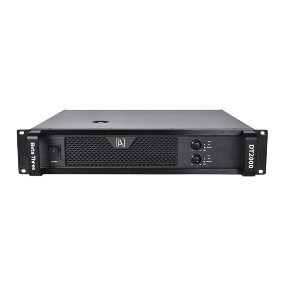
Page 7: 4、 Front Panel P4
4 FRONT PANEL Two Channels 3 4 5 PEAK SIGNAL POWER PROTECH CH A PEAK SIGNAL POWER POWER PROTECH CH B 1 Power switch 5. Channel A power/protect indicator 2 Volume control of Channel A 6. Cooling vents 3 Channel A peak indicator 7. -
Page 8: 5、 Front Panel Indicator P5
5. FRONT PANEL INDICATOR Each power/protect LED indicator is an individual indication of each channel. 1 Indication of power ON/OFF 2 Indication of system status: the green light indicates it is in normal operation, and the orange light means it is in protection mode. The following conditions will cause the power/protect LED indicator to light up: A When the system is in preparation state within 6 seconds after powering on the amplifier, and the protective muting is triggered to prevent noise emitting from the loudspeaker. - Page 9 Four Channels 15 16 1. Channel A power output (NL4 jack) 10. Channel D power output (NL4 jack) 2. Channel C power output (NL4 jack) 11. Limiter mode switch 3. Channel A signal output(TRS jack, 12. Sensitivity mode switch parallel with input A) 13.
-
Page 10: 7、 Power Supply P7
7. POWER SUPPLY a. Make sure the local voltage complies with the voltage requirement indicated on the back label of the amplifier before connecting the amplifier to the power socket. b. Make sure the power cord and the power socket are both undamaged, and whether they are compatible, before connecting the amplifier to the power socket. -
Page 11: 9、 Function Setup P8
OUTPUT CONNECTORS Each channel of this product uses a NL4 socket as the power output port. The 1+ pin of each of the NL4 socket is connected to the positive terminal of the channel power output, and the 1- pin is connected to the power ground. - Page 12 Limiter setup This series of amplifiers are designed with built-in limiters. The limiter has two optional modes to choose from (all channels share one selector switch). A 、MODE1 In this mode, the maximum output signal of the amplifier will be limited to a state where it will hardly be clipped.
- Page 13 C、32dB In this mode, the gain of the amplifier will be 32dB (X40). This mode is suitable for the array use of multiple amplifiers, or for balancing the gain of multiple amplifiers in active crossovers. This setting makes it easy to match different amplifiers with different loudspeakers with the same gain.
- Page 14 12. ADAPTABILITY OF COMPRESSION LIMITER AND POWER AMPLIFIER When connecting an external compressor limiter to this amplifier, please refer to the specification table below for settings of the compressor/limiter. Note: 1.Make sure the device of compression limiter is using dBu unit before refering to below list. 2.Make sure check the setup of sensitivity switch in advance, if the setting is for 32dB,it means the amplifier's magnification for the signal source is 32db(40times), then the relative setting of compression limiter for amplifier can be refer to below list .
- Page 15 13. COMMON PROBLEMS AND TROUBLESHOOTING Troubleshooting Failure Phenomena Check whether the AC plug of the amplifier is in proper contact with the power outlet. No sound, and the Check whether the power outlet has the correct AC power indicator is not lit voltage.
- Page 16 14. SAFETY USE SAFETY REGULATIONS ABNOMAL PHENOMENON Please turn off the power and pull out the cord if the device has any unusual sound or smell during operation. POWER CORDS PROTECTION Power plug contact and separation socket must be handled properly. Do not touch the power cord with wet hands to avoid electric shock.
- Page 17 DT SERIES PROFESSIONAL POWER AMPLIFIER www.beta3pro.com...
Need help?
Do you have a question about the DT Series and is the answer not in the manual?
Questions and answers