
Related Manuals for Hedson IRT POWERCURE


Summary of Contents for Hedson IRT POWERCURE
- Page 1 Operation Manual IRT POWERCURE Infrared-drying arch for vehicles 701006 rev 7 ©Hedson Technologies AB 2018...
-
Page 2: Table Of Contents
These booths must be conform to the European product standard EN 12215 (spray booths) and EN 13355 (combined spray and drying booths). The control system of the IRT PowerCure comprises the following functions: • Inhibition of spraying during the drying process •... -
Page 3: Product Description
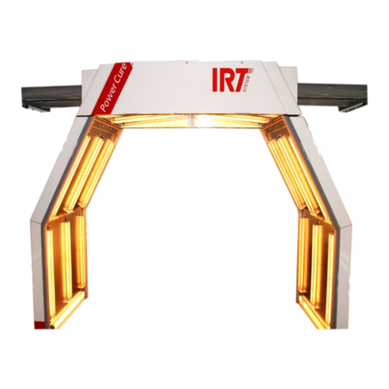
2. Product description TECHNICAL DATA Rated voltage 400V~3Ph/PE ±5% The IRT PowerCure generates infrared radiation, which heats the coating directly on a vehicle. The arch is motor- Nominal frequency 50 Hz ized and automatically moves along the wall rails in the... -
Page 4: Safety Instructions
Training instructions for operators 3.1.5 Disposal Dispose of used items at the nearest environmental Instructions to the owner: in order to meet safety facility for recycling. requirements, the owner of the paint curing system must ensure the instructions on arch usage and function are System safety available to those working with the arch. - Page 5 Angle both arch sides Communication Spray air mode Parking status with arch Parking garage Move the arch Curing distance Spray booth Car direction status mode Power to arch status Spray booth status Doors status 5.1.4. 5.1.5. SINGLE BOOTH Choice of lamps 4.1.4 Selection of coating materials and colour group 4.1.7 Manual Select the type of paint in the menu on the right side...
-
Page 6: Start-Up / Operation
4.1.11 Setup Setup on the main menu contains various settings to facilitate the use of the panel; - Show cursor - View arch status (during curing) - Automatic lamp test The configuration options for “Drying recipes” and “Car size” are only available using a PIN code for the ad- vanced user. -
Page 7: Care And Maintenance
Trouble Shooting NOTE: If you have more than one spray booth, you must specify which booth you want to use. Make this selection Drying does not start in the upper left corner of the panel. Check alarms Warning! Make sure that no one is inside the booth, and Roller door in wrong position (down) (closed) (indi- that no combustible material is lying on the floor. - Page 8 3. The lamps are secured by a screw at each end. Loosen them so far as to free the lamp ends (see Figure 7.2) (For extended service, see «IRT PowerCure» art nr 701035) Figure 7.2 701006 rev 7...
-
Page 9: Installation And Transport
7. Installation and transport 9. Spare parts list Installation Spare parts list The control panel must be located outside the booth in MECHANICAL SPARE PARTS a place with full visibility into the booth (e.g. close to an inspection window). In case that the arch is intended for Part No Description Req. -
Page 10: Certificate Of Conformity
HEDSON TECHNOLOGIES AB Hammarvägen 4 SE-232 37 ARLÖV Sweden declare under our sole responsibility that the product: IRT PowerCure that this declaration relates to conform with the following standards or other normative docu- ments: SS-EN 60204-1, EN 12100-1, EN12100-2 EN 61000-6-3, EN61000-6-2,... -
Page 11: Annex I, Acceptance Test
ANNEX I, Acceptance test Acceptance test carried out by the responsible assembler / electrician prior to commissioning. Copy for the system System Type supplier Ref. Software version Issued by Date Electrical part Mechanical part VISUAL INSPECTION MONITORING DEVICE AND OPERATOR STATION Power supply properly fused. - Page 12 © Hedson Technologies 2018 The manufacturer reserves the right to introduce technical modifications. HEDSON TECHNOLOGIES AB HEDSON TECHNOLOGIES AB Hammarvägen 4, 232 37 Arlöv Box 1530, SE-462 28 Vänersborg Tel +46 (0) 40 53 42 00 Tel +46 (0) 521 28 12 30...
Need help?
Do you have a question about the IRT POWERCURE and is the answer not in the manual?
Questions and answers