Vinotemp WINE-MATE VINO-3500HZD Service Manual
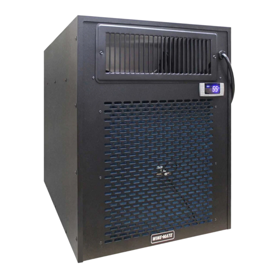
Wine-mate cooling unit
Hide thumbs
Also See for WINE-MATE VINO-3500HZD:
- Service manual (28 pages) ,
- Use & care manual (25 pages) ,
- Use and care manual (24 pages)
Table of Contents
Advertisement
Quick Links
Advertisement
Table of Contents

Related Manuals for Vinotemp WINE-MATE VINO-3500HZD


Summary of Contents for Vinotemp WINE-MATE VINO-3500HZD
- Page 1 WINE-MATE Cooling Unit Service Manual VINO-3500HZD VINO-4500HZD VINO-6500HZD VINO-8500HZD Vinotemp International Inc.
- Page 2 SAFETY INFORMATION - 1 -...
-
Page 3: Table Of Contents
TABLE OF CONTENTS Introduction………………………………………………..3 I. Goals and Objectives…………………….…...……………………………3 II. R134a Refrigerant Service Information.....…………..…….3 Component Information and Access………………….5 I. Model and Serial Label Location…………………………………………5 II. Component Access…………………………………………………………6 1) Removing the Outer Cover…………………………..……………...…..6 2) Removing the Inner Styrofoam ..……………………………..6 3) Removing the Fan Plate….…………………..…………………………..8 4) Removing the Temperature Controller…..……..……………………..9 5) Removing the Thermistor…………………………………………….10 6) Removing Fan Motors…………………………………………………...10... -
Page 4: Introduction
1. Introduction VINOTEMP assumes no responsibility for any repairs made on products by anyone other than authorized service technician This manual has been prepared to provide the information on installing, servicing, troubleshooting and repairing procedures for the WINE-MATE VINO3500HZD, 4500HZD, 6500HZD and 8500HZD cooling units. - Page 5 • Use dry nitrogen to purge the system. • Do not overcharge the refrigeration system. • Do not leave replacement compressor open to the atmosphere for more than 10 minutes. • Do not operate the compressor without refrigerant charge in the system. •...
-
Page 6: Component Information And Access
2. Component Information and Access This section provides you the component information and access inside the cooling unit. The components and their locations are shown Figures 2-1 through 2-11 below. I. Model Number & Serial Label Label Figure 2-1 - 5 -... -
Page 7: Component Access
II. Component Access 1) Removing the Outer Cover 1. Unplug the cooling unit or disconnect power. 2. Remove the cooling unit from the wine enclosure. 3. To remove the outer cover, remove all screws from each side. Figure 2-2 2) Removing the Inner Styrofoam Once the outer cover is removed, this will expose the inner styrofoam pieces. - Page 8 Figure 2-3 Figure 2-4 - 7 -...
-
Page 9: Removing The Fan Plate
Figure 2-5 3) Removing the Fan Plate 1. Disconnect the power cord, compressor cord and temperature controller wires from the terminal block. 2. Remove the 6 rivets on the front and rear sides. 3. Remove the fan plate Figure 2-6 - 8 -... -
Page 10: Removing The Temperature Controller
Figure 2-7 4) Removing the Temperature Controller Figure 2-8 1. Unplug the cooling unit or disconnect power. 2. Remove the outer cover. 3. Remove all the lower side styrofoam pieces. 4. Disconnect all the wires from the temperature controller. 5. Press the 2 snappers to release the controller and then pull it out of the opening. -
Page 11: Removing The Thermistor
5) Removing the Thermistor 1. Unplug the cooling unit or disconnect power. 2. Remove the outer cover. 3. Remove all the upper and lower side styrofoam pieces. 4. Remove the fan plate. 5. Disconnect the thermistor from the temperature controller. 6. -
Page 12: Removing The Compressor
6. Remove the overload protector by pulling straight out away from the compressor terminal. Figure 2-10 9) Removing the Compressor Figure 2-11 1. Unplug the cooling unit or disconnect power. 2. Remove the outer cover. 3. Remove all the upper and lower styrofoam pieces. 4. -
Page 13: Removing The Condenser
5. Place piercing valves onto the process tubes and discharge the refrigerant into an approved R134a recovery system. 6. Use a tubing cutter to remove the suction line and discharge line from the compressor. 7. Remove 4 nuts (11mm) from the feet of the compressor. 8. -
Page 14: Servicing And Diagnosis
Servicing and Diagnosis This section instructs you how to service each component inside the cooling unit. I. Component Checking 1) Terminal Block Figure 3-1A (3 button controller) A. Live Line (115VAC/60Hz): red shrunk wire from the power line; B. Neutral Line: white shrunk wire from the power line; C. -
Page 15: Compressor
D. Fan Wires: black shrunk wire from the fan terminal connecting the black wire from the controller compressor output; white shrunk wire from fan terminal connecting the neutral line; Figure 3-1B (5 button controller) A. Live Line (115VAC/60Hz): red shrunk wire from the power line B. - Page 16 A. Resistance 1. Unplug WINEMATE cooling unit or disconnect power. 2. Remove the terminal cover from the compressor. 3. Remove the start relay and overload protector from the compressor. If wiring is removed from the start relay and/or overload protector, carefully label each wire according to its proper location.
-
Page 17: Start Relay
3) Start Relay A start relay’s function is to energize and de-energize the compressor’s start winding. The coil of the current type relay is connected in series with the run winding. When current flows through the coil, a magnetic force is produced, pulling the relay plunger up. -
Page 18: Fan Motors
the temperature controller will turn on the compressor and fan motors. Once the selected temperature is sensed, the controller will turn off the cooling unit. A. Resistance 1. Unplug WINE-MATE cooling unit or disconnect power. 2. Disconnect the red and white wires connected to the input 7 and 8 of the temperature controller. -
Page 19: Thermistor
1. The WINE-MATE unit needs to be plugged in. 2. Locate the red and white wires going to the temperature controller input 7 and 8. 3. Set the voltmeter to the AC 200 scale. 4. Touch and hold one voltmeter probe to one of the wire terminals, then touch and hold the other probe to the other wire terminal 5. -
Page 20: Wiring Diagram
4. The ohmmeter shall show a reading of tens ohms. 5. Reconnect the wires to the proper terminals as previously marked. B. Live voltage 1. The WINEMATE unit needs to be plugged in and turned on. 2. Locate the black and white wires from the fan motor being tested and follow them back to the terminal block. -
Page 21: Troubleshooting Chart
Figure 3-5B (5 button controller) III. Troubleshooting Chart This Troubleshooting Chart is not prepared to replace the training required for a professional refrigeration service person, not is it comprehensive. Table 3-1 Troubleshooting Chart Complaint Possible Causes Response a. Power cord not plugged a. - Page 22 rising high a. Air probe a. When using an air probe, the wine 3. Temperature bottle temperature mainly fluctuating controlled average temperature. If the set-point is 55 ° with the differential 4F, the cooling unit turns ° temperature (It may be higher than F if it is in anti-short cycle or °...
- Page 23 c. Ambient temperature higher > c. Check for installation location ° d. Leave minimum 3 feet clearance for d. Exhaust restricted the hot air exhaust side and leave minimum 1 foot clearance for the fresh air intake side e. Clean condenser e.
- Page 24 d. Water passages restricted d. Clean the drip tray e. Drip tray leak (No water overflow e. Seal the leak using silicone sealant but water leak) a. Air leak in the wine cellar causing a. Check for any air leak 15.Excessive excessive condensate condensate...
-
Page 25: Customer Support
4. Customer Support If you still have problems, please contact us at: Vinotemp International 17631 South Susana Road Rancho Dominguez, CA 90221 Tel: (310) 886-3332 Fax: (310) 886-3310 Email: info@vinotemp.com - 24 -... -
Page 26: Warranty Information
BTU/H. While every effort has been made to provide accurate guidelines, VINOTEMP can not warranty its units to cool a particular enclosure. In case of failure, VINOTEMP cooling units must be repaired by the factory or its authorized agent. Repairs or modifications made by anyone else will void the warranty. -
Page 27: Limitation Of Implied Warranty
TO, IMPLIED WARRANTIES OF MERCHANTABILITY OR FITNESS FOR A PARTICULAR PURPOSE. While great effort has been made to provide accurate guidelines VINOTEMP cannot warrant its units to properly cool a particular enclosure. Customers are cautioned that enclosure construction, unit location and many other factors can affect the operation and performance of the unit.
Need help?
Do you have a question about the WINE-MATE VINO-3500HZD and is the answer not in the manual?
Questions and answers