Advertisement
Quick Links
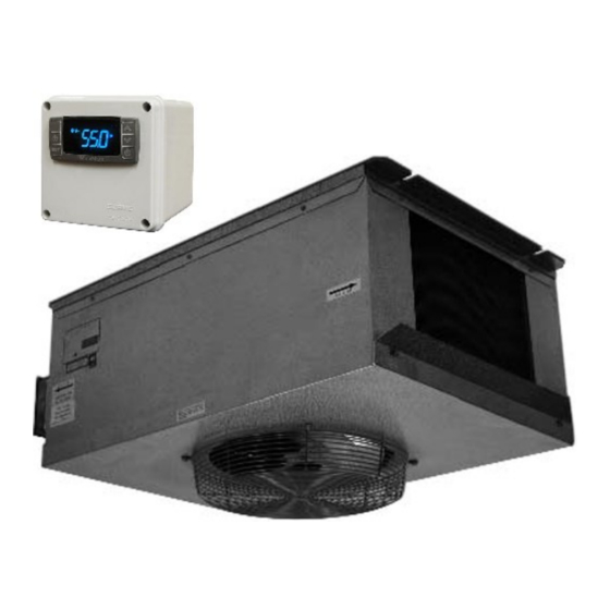
Split Ceiling-Mounted Cooling System
Operation Care Installation Manual
WM-2520SSD WM-2520SSD-LA
WM-4520SSD WM-4520SSD-LA
WM-6520SSD WM-6520SSD-LA
WM-8520SSD WM-8520SSD-LA
R
e
a
d
R
e
a
d
Vinotemp International Corp
732 South Racetrack Road, Henderson, NV 89015
Tel: (800) 777-VINO Fax: (310) 886-3310 Email: info@vinotemp.com
w
w
w
.
v
i
n
o
t
e
m
w
w
w
.
v
i
n
o
t
e
m
a
n
d
s
a
v
e
t
h
e
a
n
d
s
a
v
e
t
h
e
p
.
c
o
m
p
.
c
o
m
s
e
i
n
s
t
r
u
c
t
i
o
n
s
e
i
n
s
t
r
u
c
t
i
o
n
s
s
Advertisement

Related Manuals for Vinotemp WINE-MATE WM-2520SSD


Summary of Contents for Vinotemp WINE-MATE WM-2520SSD
- Page 1 Split Ceiling-Mounted Cooling System Operation Care Installation Manual WM-2520SSD WM-2520SSD-LA WM-4520SSD WM-4520SSD-LA WM-6520SSD WM-6520SSD-LA WM-8520SSD WM-8520SSD-LA Vinotemp International Corp 732 South Racetrack Road, Henderson, NV 89015 Tel: (800) 777-VINO Fax: (310) 886-3310 Email: info@vinotemp.com...
- Page 2 Important Safety Information - 1 -...
-
Page 3: Table Of Contents
Table of Contents Cellar Construction Guide------------------------------------------3 Features & Specifications------------------------------------------4 Temperature & Humidity--------------------------------------------6 Care Guide-------------------------------------------------------------10 User’ Troubleshooting---------------------------------------------11 Installer’s Instructions---------------------------------------------14 Electrical Wirings----------------------------------------------------27 Warranty----------------------------------------------------------------30 - 2 -... -
Page 4: Cellar Construction Guide
Cellar Construction Guide This is only a guide and shall be considered as the minimum requirements. All interior walls, ceilings and floors shall have a vapor barrier and a minimum of R13 insulation. All exterior walls and ceiling shall have a vapor barrier and a minimum of R19 insulation. -
Page 5: Features & Specifications
Features and Specifications WINE~MATE split ceiling-mounted cooling systems WM-2520~8520SSD and WM-2520~8520SSD-LA are designed to provide a cold environment between 50~65 °F with a humidity range within 50~70% RH for a properly insulated wine cellar. These temperature and humidity ranges are optimized for long term storage of wine like that in natural caves. - Page 6 If the condensing unit will operate below 50°F, install a low CAUTION ambient condition kit. The cooling capacity is determined under 55°F cellar temperature, 75°F cellar ambient temperature and 90°F condensing unit ambient temperature, with R13 interior and NOTE R19 exterior insulations. Higher ambient temperatures or lower insulations will cause reducing capacity and the cellar temperature may not be maintained at 55°F.
-
Page 7: Temperature & Humidity
Temperature and Humidity 1. The controller Fig. 2 TEMPERATURE CONTROLLER 1) Keys SET: To display set-point; in programming mode it selects a parameter or confirms an operation. : To start a manual defrost. : To see the maximum stored temperature; in programming mode it browses the parameter codes or increases the displayed value. - Page 8 4) Alarm Signals The alarm codes are described as follows. MESSAGE CAUSE FUNCTION Temperature probe faulty Compressor switching to Con and CoF Probe temperature ALU higher than the High temperature alarm setting temperature; Outputs unchanged Probe temperature ALL lower than the Low temperature alarm setting temperature;...
- Page 9 5. Manual Defrost Press and hold the defrost key until defrost starts. The defrost indicator will be 6. Parameter Programming 1) Press and hold the SET + keys until the “°C” or “°F” LED starts flashing, then release the keys. 2) Press and hold again the SET + keys until the Pr2 label is displayed, then release the keys.
- Page 10 7. How to calibrate the air probe If the actual cellar temperature differs from the setting temperature, set parameter ot = actual cellar temperature minus set-point. 8. How to adjust defrost settings In case there is excessive frost, the parameters FnC = C-y, idF = 4 and MdF = 20 can be used to avoid frost.
-
Page 11: Care Guide
Care Guide In general, always unplug system or disconnect power while doing care. 1. Condenser Coil Cleaning Clean the condenser coil regularly. Coil may need to be cleaned at least every 6 months. Use a vacuum cleaner with an extended attachment to clean the coil when it is dusty or dirty. -
Page 12: User' Troubleshooting
User’s Troubleshooting This Troubleshooting Chart is not prepared to replace the training required for a professional refrigeration service person, not is it comprehensive. Complaint Possible Causes Response 1. Unit not running a. Power cord not plugged a. Check power cord b. - Page 13 minimum 1 foot clearance for the ambient air intake side e. Malfunctioning fans e. Check for both evaporator and condenser fans Evaporator or condenser airflow Check for air restrictions, air short- circulation, grille directions g. Dirty Condenser g. Clean condenser h.
- Page 14 c. Not stopping due to air leak, high c. Check seal, door opening, ambient temperature ambient temperature temperature setting temperature setting d. Defective controller or probe d. Check for controller and probe e. Low ambient temperature e. Change defrost settings f.
-
Page 15: Installer's Instructions
WINE~MATE split system is shipped as components and is ready for use only after a certified refrigeration technician has properly installed the system. Proper installation is critical. Vinotemp can only warrant the quality of the components. The installation and proper operation of the system must be warranted by the installer. - Page 16 Parts not included: Liquid line copper tubing Suction line copper tubing Liquid and suction line locations may differ from that they are CAUTION shown below, please check on the units for proper installations. To prepare rough-in, leave minimum 4” clearances for electrical NOTE wiring and refrigeration piping.
- Page 17 Fig. 4 WM-252~452SFCD Evaporator Unit Fig. 5 WM-652~852SFCD Evaporator Unit - 16 -...
- Page 18 Fig. 6 WM-252~452SCUR Condensing Unit Fig. 7 WM-652~852SCUR Condensing Unit - 17 -...
- Page 19 Fig. 8 WM-Liquid Filter Fig. 9 WM-Liquid Indicator 2. Temperature Controller and Air Probe Location 1) The temperature controller can be mounted either inside or outside the wine cellar, but the air probe must be located inside. 2) The air probe shall be located in the wine cellar 5 ft above the floor or the air return area, but it shall not be located in the air supply area or other areas where air is not circulated.
- Page 20 1) Place the condensing units WM-252~852SCUR in a properly ventilated location. Otherwise, heat exhausted by the condensing unit will build up and the cooling system will not operate properly. 2) Condensing unit shall be elevated to avoid possible flooding and shaded from direct sun.
- Page 21 6) Hook up the drain line and check if water drains. 6. Connecting Electrical Wires Connect all electrical components using the wiring diagrams in accordance with all state and local codes. 7. Evacuating, Charging and Starting the System 1-Manifold High or Low Pressure Hose; 2-Receiver Discharge or Compressor Suction Port;...
- Page 22 If the unit is equipped with a low ambient condition kit and installed in the summer, add 15% more refrigerant. If the low ambient condition kit is used, turn off the compressor before power the condensing unit. Only turn on the compressor after the condensing unit has been powered for 12 hours.
- Page 23 B. PS2 Dual Control Fig. 13 Adjustable Pressure Control III. Low ambient condition kit (if applicable) The crankcase heater The crankcase heater is installed at the bottom of the compressor and shall be turned on all the time. The heater is self-regulated. The condenser fan control The condenser fan control is installed at the high side.
- Page 24 Fig. 14 Condenser Fan Cycle Control 2) The subcooling at the condensing unit shall be around 10°F. The charge may be complete when there are no more bubbles forming in the liquid indicator. 3) The head pressure shall be 120 ~ 150 psig at 70 ~ 90 °F condensing unit operating temperatures.
- Page 25 9) Turn both discharge and suction valves in the back positions. 10) Disconnect the manifold. 9. Pressure, Superheat and Subcooling Readings To read properly, the service valves must be in the middle CAUTION positions. Complaint Possible Causes 1) High suction pressure and low head 1) Compressor may be bad pressure Zero superheat and zero subcooling...
- Page 26 pressure High superheat and normal subcooling 13) Low suction pressure and high head 13) Both evaporator pressure condenser restricted; liquid High superheat and high subcooling and suction lines connected wrong 14) Low suction pressure and high head 14) Liquid line restricted before pressure receiver High superheat and high subcooling...
- Page 27 Electrical Wiring Diagrams Hidden lines are the field wirings Use minimum 14 gauge wires for power lines. CAUTION If equipped with low ambient condition kit, use low ambient temperature wiring diagrams. A safety switch is always recommended for the condensing unit. Fig.
-
Page 28: Electrical Wirings
Fig. 17 WM-2520~4520SSD-LA Electrical Wiring Diagram Fig. 18 WM-6520~8520SSD Electrical Wiring Diagram - 27 -... - Page 29 Fig. 19 WM-6520~8520SSD-LA Electrical Wiring Diagram - 28 -...
-
Page 30: Warranty
BTU/H. While every effort has been made to provide accurate guidelines, VINOTEMP can not warranty its units to cool a particular enclosure. In case of failure, VINOTEMP cooling units must be repaired by the factory or its authorized agent. Repairs or modifications made by anyone else will void the warranty. - Page 31 VINOTEMP will, at its discretion, repair or replace the unit and return it free of charge to the original retail customer. If the unit is found to be in good working order, or beyond the initial twelve month period, it will be returned freight collect.
Need help?
Do you have a question about the WINE-MATE WM-2520SSD and is the answer not in the manual?
Questions and answers