Table of Contents
Advertisement
Advertisement
Table of Contents
Troubleshooting

Related Manuals for Calix ODC-80


Summary of Contents for Calix ODC-80
- Page 1 Calix ODC-80 Installation Guide July 2003 Part #220-00029, Rev. 11...
-
Page 3: Table Of Contents
TABLE OF CONTENTS Before You Begin Installing the ODC-80 Product Overview and Access ............3 Overview and dimensions of the ODC-80 cabinet......3 Front access ................5 Side splice access ..............6 Rear access................7 Opening and closing compartment doors ........8 Battery access ................ - Page 4 Maintaining the Calix Outdoor Cabinet........71 Battery Maintenance ..............71 Maintain external cable connections .........72 Maintain the cabinet surfaces ..........73 Proprietary Information: Not for use or disclosure except by written agreement with Calix. © 2001-2003 Calix. All Rights Reserved. ODC-80 Installation Guide...
- Page 5 Customer Service and Support ........... 99 The Calix Technical Assistance Center ........99 Appendix: Specifications ............101 ODC-80 cabinet specifications..........101 Proprietary Information: Not for use or disclosure except by written agreement with Calix. © 2001-2003 Calix. All Rights Reserved. ODC-80 Installation Guide...
-
Page 7: Before You Begin Installing The Odc-80
Chapter Before You Begin Installing the ODC-80... -
Page 9: Product Overview And Access
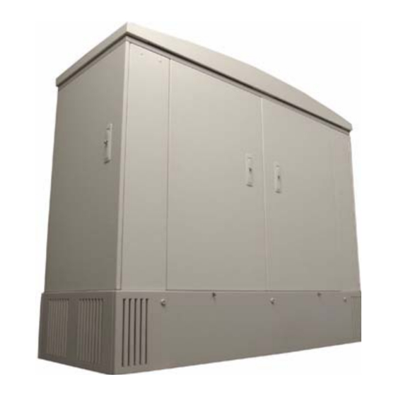
1920 lines of copper and fiber service. ODC-80 description You can configure the Calix ODC-80 for copper service, fiber service, or a combination of both. You can also migrate from copper to fiber service in the field. - Page 10 2300 pounds 1043 kilograms (3900 pounds equipped with (1769 kilograms equipped with batteries) batteries) ODC-80 dimensions Proprietary Information: Not for use or disclosure except by written agreement with Calix. © 2001-2003 Calix. All Rights Reserved. Calix ODC-80 Installation Guide...
-
Page 11: Front Access
Front access The front of the ODC-80 provides access to the equipment compartments for 4 Calix C7 shelves and power distribution equipment. Equipment in the front compartment Equipment in the front compartments of an ODC-80 include: • AC load center with AC entry •... -
Page 12: Side Splice Access
Side splice access The side compartments of the ODC-80 provide access to entry and splicing areas for subscriber fiber, copper cable, AC entry, and ground. Fiber splicing in the right side compartment The fiber splice compartment is on the right side as you face the cabinet. This compartment contains: •... -
Page 13: Rear Access
Rear access The rear of the ODC-80 provides access to the copper protection compartments and the backs of 4 Calix C7 shelves. Copper protection in the rear compartments The copper protection in the rear compartments contains 8 panels holding 40 copper protection blocks for the 4 Calix C7 shelves. -
Page 14: Opening And Closing Compartment Doors
If the handle does not lock in place, insert and turn the key until it clicks. Then, press the handle latch into place. Proprietary Information: Not for use or disclosure except by written agreement with Calix. © 2001-2003 Calix. All Rights Reserved. -
Page 15: Battery Access
On the panel, remove the ground strap from the panel. Set the battery compartment panel out of your way. Proprietary Information: Not for use or disclosure except by written agreement with Calix. © 2001-2003 Calix. All Rights Reserved. Calix ODC-80 Installation Guide... - Page 16 Insert the key into a latch and turn it clockwise until the inner keyhole notch aligns with the outer keyhole notch. Repeat for all latches on the panel. Proprietary Information: Not for use or disclosure except by written agreement with Calix. © 2001-2003 Calix. All Rights Reserved. Calix ODC-80 Installation Guide...
-
Page 17: Cooling Fan Access
Lift the roof of the cabinet to access the cooling fans. Location of roof retaining bolts The ODC-80 roof is held in place by 3 retaining bolts at the front of the cabinet. Procedure to open the roof of the cabinet... - Page 18 5/16" allen wrench. An allen wrench is provided with the cabinet. Proprietary Information: Not for use or disclosure except by written agreement with Calix. © 2001-2003 Calix. All Rights Reserved. Calix ODC-80 Installation Guide...
-
Page 19: Installation Prerequisites
Install a ground rod, or similar grounding device, with a maximum resistance to ground of 20 ohms near the pad site. See the "Calix ODC-80 Pour-In-Place Template Instructions" if you plan to construct the pad using a Calix template. Footprint dimensions Recommended pad dimensions are 148 inches by 96 inches;... -
Page 20: Cable Requirements
Use a fiber splice value no greater than 0.5 dB loss. • Leave 6 feet of cable above the top of the pad. Proprietary Information: Not for use or disclosure except by written agreement with Calix. © 2001-2003 Calix. All Rights Reserved. Calix ODC-80 Installation Guide... -
Page 21: What You Need To Bring
Analog test set (for testing POTS lines) • DS1 test set • DS3 test set • ADSL test set • Optical power meter Proprietary Information: Not for use or disclosure except by written agreement with Calix. © 2001-2003 Calix. All Rights Reserved. Calix ODC-80 Installation Guide... -
Page 22: What You Get With The Cabinet
What you get with the cabinet Items in the installation kit The following items are shipped inside the battery tray of the ODC-80 as an installation kit: • Calix coffee cup with lid (quantity 2) • 2-inch cold shrink tubing (quantity 4) •... -
Page 23: Placing The Odc-80 On A Pad
Chapter Placing the ODC-80 on a Pad... -
Page 25: Pad Mounting The Cabinet
Unpack the cabinet The cabinet ships bolted to a shipping pallet and enclosed in a cardboard box. Location of mounting studs The ODC-80 is fastened with 5 mounting studs in the locations shown. Procedure to unpack the ODC-80 Step Action Remove the cardboard shipping box. -
Page 26: Prepare The Cabinet For Placement
Attach lifting straps the to lifting details. Suspend the cabinet approximately 2 feet (61 cm) above the pad. Proprietary Information: Not for use or disclosure except by written agreement with Calix. © 2001-2003 Calix. All Rights Reserved. Calix ODC-80 Installation Guide... -
Page 27: Lower And Bolt
Lower the cabinet onto the mounting studs in the pad and fasten it securely. Location of mounting studs The ODC-80 is fastened with 5 mounting studs in the locations shown. Procedure to lower and bolt the cabinet to a pad... - Page 28 Repeat at the rear of the cabinet. Close the rear battery compartment panel. See the battery access procedure. Proprietary Information: Not for use or disclosure except by written agreement with Calix. © 2001-2003 Calix. All Rights Reserved. Calix ODC-80 Installation Guide...
-
Page 29: Seal The Cabinet
Cover any unused cable entry ports with the blank plates provided. Proprietary Information: Not for use or disclosure except by written agreement with Calix. © 2001-2003 Calix. All Rights Reserved. Calix ODC-80 Installation Guide... -
Page 31: Installing Power, Subscriber Cables, And Equipment
Chapter Installing Power, Subscriber Cables, and Equipment... -
Page 33: Connecting Power And Ground
Secure the terminal lug of the ground cable to the ground bar stud. Tighten the strain relief fitting to secure the ground cable. Proprietary Information: Not for use or disclosure except by written agreement with Calix. © 2001-2003 Calix. All Rights Reserved. Calix ODC-80 Installation Guide... - Page 34 Attach the second lead from the Ohm meter to the ground bar. Verify that the Ohm meter reads 1 Ohm or less. Proprietary Information: Not for use or disclosure except by written agreement with Calix. © 2001-2003 Calix. All Rights Reserved.
-
Page 35: Install And Test The Ac Power
Requirements for AC power input. The Calix outdoor cabinet requires a 240-220 VAC power feed with 60 Amp service. DANGER! High voltage may be present. Do not turn on the main power to the cabinet until the installation is complete. - Page 36 Note: ODC-10 and ODC-20 pegboards have 3 screws per side. Remove the wall plate located above the AC entry tray. Proprietary Information: Not for use or disclosure except by written agreement with Calix. © 2001-2003 Calix. All Rights Reserved. Calix ODC-80 Installation Guide...
- Page 37 AC cables in the AC entry tray c. pull the cables through to the AC Load Center. Proprietary Information: Not for use or disclosure except by written agreement with Calix. © 2001-2003 Calix. All Rights Reserved.
- Page 38 Run the black hot lead to the L1 side of the breaker. Run the red hot lead to the L2 side of the breaker. Proprietary Information: Not for use or disclosure except by written agreement with Calix. © 2001-2003 Calix. All Rights Reserved.
- Page 39 In the front equipment compartment, re-attach the AC load center front panel. In the side splice compartment, re-attach the AC cover plate over the AC entry tray. Proprietary Information: Not for use or disclosure except by written agreement with Calix. © 2001-2003 Calix. All Rights Reserved. Calix ODC-80 Installation Guide...
-
Page 40: Install And Test Rectifier Modules
Description of the 60 AMP power shelf The Calix 60 AMP power shelf contains an alarm control unit on the left and slots for four rectifier modules on the right. Each rectifier module has its own power switch and alarm and status indicators. - Page 41 1, 2, and 3, and set to OFF for position 4. Set the rectifier module AC switch to ON. Proprietary Information: Not for use or disclosure except by written agreement with Calix. © 2001-2003 Calix. All Rights Reserved. Calix ODC-80 Installation Guide...
- Page 42 -54.5 +/-.5 VDC At the AC Load center, set all the breakers to OFF. Proprietary Information: Not for use or disclosure except by written agreement with Calix. © 2001-2003 Calix. All Rights Reserved.
-
Page 43: Install And Test The Batteries
Install and test the batteries Install a battery string into each battery tray in the cabinet base. The Calix ODC-80 uses 4 battery strings. Calix recommends using Dynasty 125 AH batteries. Procedure to prepare for battery installation Step Action Check that main power to the cabinet is ON, then at the AC load center, set the Rectifier (A), Rectifier (B), and Main breakers to ON. - Page 44 Dynasty recommends 110 in.-lbs. or (12.4 n-m). Proprietary Information: Not for use or disclosure except by written agreement with Calix. © 2001-2003 Calix. All Rights Reserved. Calix ODC-80 Installation Guide...
- Page 45 -46 and -54 VDC Set the battery breaker switch for each drawer to ON. Proprietary Information: Not for use or disclosure except by written agreement with Calix. © 2001-2003 Calix. All Rights Reserved.
- Page 46 52 VDC At the AC load center, set the Main breaker to OFF to check that the batteries supply power to the cabinet. The fan trays in the Calix C7 should continue to run.
-
Page 47: Install And Test The Fan Tray
Install and test the fan tray Installing a fan tray into a Calix C7 shelf in the front compartment of the cabinet provides cooling for the Calix C7 shelf. The front panel of the fan tray also shows the results of a power test at start-up, and provides status displays and interfaces for testing. - Page 48 (Note: In the locked position, the handle should be flush with the bottom lip of the shelf.) Proprietary Information: Not for use or disclosure except by written agreement with Calix. © 2001-2003 Calix. All Rights Reserved. Calix ODC-80 Installation Guide...
-
Page 49: Installing Outside Plant Cables
For best results with a high copper count configuration, route the cable to the right. Note Proprietary Information: Not for use or disclosure except by written agreement with Calix. © 2001-2003 Calix. All Rights Reserved. Calix ODC-80 Installation Guide... - Page 50 Proprietary Information: Not for use or disclosure except by written agreement with Calix. © 2001-2003 Calix. All Rights Reserved. Calix ODC-80 Installation Guide...
- Page 51 After the subscriber cable is installed and sealed, route the cable over the cable management pegs along with the factory installed equipment cables. Proprietary Information: Not for use or disclosure except by written agreement with Calix. © 2001-2003 Calix. All Rights Reserved. Calix ODC-80 Installation Guide...
- Page 52 The figure shows the labels for slot 1 and where you would apply them to the copper protection block. Proprietary Information: Not for use or disclosure except by written agreement with Calix. © 2001-2003 Calix. All Rights Reserved. Calix ODC-80 Installation Guide...
-
Page 53: Install The Fiber Holders
72 fiber connections. Jumper options From the front of a Calix C7 optical plug-in card, you can run a fiber jumper to a fiber distribution cassette. You can also run a jumper between the fiber splice tray and the fiber distribution cassette. - Page 54 Fiber jumper and pigtail options • From the front of a Calix C7 optical plug-in card, you can run a fiber jumper to a fiber distribution cassette. • From the front of a Calix C7 optical plug-in card, you can run a fiber pigtail to a fiber splice tray.
- Page 55 Slide the fiber trays into the holder. Secure the fiber trays to the holder with the supplied velcro strap. Proprietary Information: Not for use or disclosure except by written agreement with Calix. © 2001-2003 Calix. All Rights Reserved. Calix ODC-80 Installation Guide...
-
Page 56: Install The Fiber
Pigtails are spliced to the fiber with the splices placed in the fiber splice trays. Proprietary Information: Not for use or disclosure except by written agreement with Calix. © 2001-2003 Calix. All Rights Reserved. Calix ODC-80 Installation Guide... - Page 57 Insert the fiber distribution cassette into the holder. Procedure to terminate the fiber cables Proprietary Information: Not for use or disclosure except by written agreement with Calix. © 2001-2003 Calix. All Rights Reserved. Calix ODC-80 Installation Guide...
- Page 58 If desired, run fiber pigtails from the fiber distribution cassette(s) to the corresponding fiber splice tray. Use velcro around the splice tray ends to simplify cable management. Proprietary Information: Not for use or disclosure except by written agreement with Calix. © 2001-2003 Calix. All Rights Reserved. Calix ODC-80 Installation Guide...
- Page 59 Proprietary Information: Not for use or disclosure except by written agreement with Calix. © 2001-2003 Calix. All Rights Reserved. Calix ODC-80 Installation Guide...
-
Page 60: Install Other Fiber And Cable Management Accessories
Install other fiber and cable management accessories Calix ships each cabinet with brackets that you can use to mount equipment or accessories in the splice compartment. Description of the accessory brackets The accessory brackets are 6" high and 5-5/8" deep. -
Page 61: Installing Plug-In Cards
Push the card ejector up into the locked position. Proprietary Information: Not for use or disclosure except by written agreement with Calix. © 2001-2003 Calix. All Rights Reserved. Calix ODC-80 Installation Guide... - Page 62 AMP installation view Proprietary Information: Not for use or disclosure except by written agreement with Calix. © 2001-2003 Calix. All Rights Reserved. Calix ODC-80 Installation Guide...
-
Page 63: Install The Calix Rap
Lock the card ejectors at the top and bottom of the card. Proprietary Information: Not for use or disclosure except by written agreement with Calix. © 2001-2003 Calix. All Rights Reserved. Calix ODC-80 Installation Guide... -
Page 64: Install The Metallic Plug-In Cards
On the card, push the card ejector up into the locked position. Proprietary Information: Not for use or disclosure except by written agreement with Calix. © 2001-2003 Calix. All Rights Reserved. -
Page 65: Install The Optical Plug-In Cards
However, it can destroy the retina of the eye. Optical plug-in card installation view Proprietary Information: Not for use or disclosure except by written agreement with Calix. © 2001-2003 Calix. All Rights Reserved. Calix ODC-80 Installation Guide... - Page 66 (Note: the Calix optical card ports are located on the face of each card and are numbered from the top of the card down -1, 2, 3, etc. - with the RX connector in the front and the TX connector immediately behind it.)
-
Page 67: System And Network Configuration
Introduction Calix iMS features The Calix integrated Management Software (iMS) is a graphical user interface that you use to configure and monitor all of the Calix C7 nodes on a network. With the Calix iMS, you can: • view a diagram of your network topology •... -
Page 68: Configure Your Computer To Connect To The Calix C7
Calix C7 iMS Guide. Calix factory settings for the front Ethernet port The Calix C7 ships with the front Ethernet port on the AMP (E1) active and set to the following configuration: IP: 192.168.1.1... - Page 69 Use a straight-through Ethernet cable to connect the Ethernet port on your computer to the Ethernet port on the front of the AMP in the Calix C7 shelf. Proprietary Information: Not for use or disclosure except by written agreement with Calix.
-
Page 70: Start The Calix Integrated Management System
Start the Calix integrated Management System You start the iMS by entering the IP address of the Calix C7 shelf into your browser. One-time install of the Java Runtime Environment The first time you start the Calix iMS, you may be prompted to: •... - Page 71 Start up view of your network The first time you log in to a new Calix C7 network, you will see the following: • An empty Work Area with no network topology. • One entry in the Navigation Tree named Unassigned Shelves.
-
Page 72: Define Nodes In The Network
In the Alarm Setting list, click either Node to display alarms only for this node, or Network to display all alarms. Proprietary Information: Not for use or disclosure except by written agreement with Calix. © 2001-2003 Calix. All Rights Reserved. - Page 73 Click Next to save all node definitions and the Admin Master designation, and to exit the Network Wizard. Proprietary Information: Not for use or disclosure except by written agreement with Calix. © 2001-2003 Calix. All Rights Reserved. Calix ODC-80 Installation Guide...
-
Page 75: Maintaining And Troubleshooting The Odc-80
Chapter Maintaining and Troubleshooting the ODC-80... -
Page 77: Maintaining The Calix Outdoor Cabinet
Cabinet Battery Maintenance At a minimum follow the battery manufacturers recommended maintenance. Additionally Calix recommends that all batteries be removed from the cabinet, tested and maintained at least once a year. Perform the following task: • Visually inspect each battery for physical damage, leakage, or bulging. Replace any battery displaying any defect before the batteries are placed back in service. -
Page 78: Maintain External Cable Connections
Check all conduits to ensure that any material used to seal between the cable and the conduit is still present and providing a complete seal. Proprietary Information: Not for use or disclosure except by written agreement with Calix. © 2001-2003 Calix. All Rights Reserved. -
Page 79: Maintain The Cabinet Surfaces
Visually inspect the inside of the cabinet for signs of visible damage to the metal or paint. • Repair damage to the paint using touch-up paint available from Calix after cleaning the surface and removing rust. • Note any damage to the metal work. If the damaged metal work interferes with the operation of the Calix C7 cabinet or electronics contact Calix support for assistance with a resolution. -
Page 81: Environmental Alarms
You will see this message once the alarm has been cleared from the system. TID-000 01-09-10 08-15-00 A 001 REPT EVT ENV "N2-1:POWER,CL,9-10,8-15-00;" Proprietary Information: Not for use or disclosure except by written agreement with Calix. © 2001-2003 Calix. All Rights Reserved. Calix ODC-80 Installation Guide... -
Page 82: Battery Circuit Breaker Alarm
You will see this message once the alarm has been cleared from the system. TID-000 01-09-10 09-20-00 A 001 REPT EVT ENV "N2-1:BATTCB,CL,9-10,8-15-00;" Proprietary Information: Not for use or disclosure except by written agreement with Calix. © 2001-2003 Calix. All Rights Reserved. Calix ODC-80 Installation Guide... -
Page 83: Auxiliary Fuse Fail Alarm
You will see this message once the alarm has been cleared from the system. TID-000 01-09-10 10-45-00 A 001 REPT EVT ENV "N2-1:FUSE,CL,9-10,10-45-00;" Proprietary Information: Not for use or disclosure except by written agreement with Calix. © 2001-2003 Calix. All Rights Reserved. Calix ODC-80 Installation Guide... -
Page 84: Cabinet Over Temperature Alarm
You will see this message once the alarm has been cleared from the system: TID-000 01-09-10 11-55-00 A 001 REPT EVT ENV "N2-1:HITEMP,CL,9-10,11-55-00;" Proprietary Information: Not for use or disclosure except by written agreement with Calix. © 2001-2003 Calix. All Rights Reserved. Calix ODC-80 Installation Guide... - Page 85 If the equipment is producing more heat than what is budgeted for equipment in the cabinet, proceed to the next step. Access the Calix C7 equipment with a computer and verify the heat setting for the shelf or shelves in the cabinet.
-
Page 86: Door Alarm
You will see this message once the alarm has been cleared from the system. TID-000 01-09-10 17-15-00 A 001 REPT EVT ENV "N2-1:OPENDR,CL,9-10,17-15-00;" Proprietary Information: Not for use or disclosure except by written agreement with Calix. © 2001-2003 Calix. All Rights Reserved. Calix ODC-80 Installation Guide... -
Page 87: Gmt Fuse Fail Alarm
You will see this message once the alarm has been cleared from the system. TID-000 01-09-10 12-15-00 A 001 REPT EVT ENV "N2-1:FUSE,CL,9-10,12-15-00;" Proprietary Information: Not for use or disclosure except by written agreement with Calix. © 2001-2003 Calix. All Rights Reserved. Calix ODC-80 Installation Guide... -
Page 88: Low Battery Alarm
You will see this message once the alarm has been cleared from the system. TID-000 01-09-10 13-15-00 A 001 REPT EVT ENV "N2-1:BATTERY,CL,9-10,13-15-00;" Proprietary Information: Not for use or disclosure except by written agreement with Calix. © 2001-2003 Calix. All Rights Reserved. Calix ODC-80 Installation Guide... -
Page 89: Low Voltage Disconnect Alarm
You will see this message once the alarm has been cleared from the system. TID-000 01-09-10 14-15-00 A 001 REPT EVT ENV "N2-1:LVD,CL,9-10,14-15-00;" Proprietary Information: Not for use or disclosure except by written agreement with Calix. © 2001-2003 Calix. All Rights Reserved. Calix ODC-80 Installation Guide... -
Page 90: Rectifier Major Alarm
The rectifier major (RECT) alarm indicates that the outdoor cabinet Major rectifier shelf has a major alarm. The Calix rectifier will report a major alarm for high voltage shut down, AC fail, Fuse Alarm, and low voltage disconnect. Alarm output... -
Page 91: Rectifier Minor Alarm
You will see this message once the alarm has been cleared from the system. TID-000 01-09-10 16-15-00 A 001 REPT EVT ENV "N2-1:RECT,CL,9-10,16-15-00;" Proprietary Information: Not for use or disclosure except by written agreement with Calix. © 2001-2003 Calix. All Rights Reserved. Calix ODC-80 Installation Guide... -
Page 93: Troubleshooting And Replacing Outdoor Cabinet Hardware
Verify cooling fan operation as part of regular cabinet maintenance. An over temperature condition will occur as the result of a failed cooling fan. Proprietary Information: Not for use or disclosure except by written agreement with Calix. © 2001-2003 Calix. All Rights Reserved. - Page 94 Replace and tighten all cartridge screws around the perimeter. Close the cabinet roof. See the roof closure procedure. Proprietary Information: Not for use or disclosure except by written agreement with Calix. © 2001-2003 Calix. All Rights Reserved. Calix ODC-80 Installation Guide...
-
Page 95: Replace A Rectifier Module
OFF for positions 3 and 4. Set the rectifier module AC switch to ON. Proprietary Information: Not for use or disclosure except by written agreement with Calix. © 2001-2003 Calix. All Rights Reserved. Calix ODC-80 Installation Guide... - Page 96 -54.5 +/-.5 VDC At the AC Load center, set all the breakers to OFF. Proprietary Information: Not for use or disclosure except by written agreement with Calix. © 2001-2003 Calix. All Rights Reserved.
-
Page 97: Replace The Batteries
Tighten the bolt to a terminal torque as specified by the battery manufacturer. Dynasty recommends 110 in.-lbs. or 12.4 n-m. Proprietary Information: Not for use or disclosure except by written agreement with Calix. © 2001-2003 Calix. All Rights Reserved. Calix ODC-80 Installation Guide... - Page 98 -46 and -54 VDC Set the battery breaker switch above each drawer to ON. Proprietary Information: Not for use or disclosure except by written agreement with Calix. © 2001-2003 Calix. All Rights Reserved.
-
Page 99: Replace The Circuit Breakers
Replace the cover to the AC load center. Set the main AC breaker, and the breaker that you just replaced, to ON. Proprietary Information: Not for use or disclosure except by written agreement with Calix. © 2001-2003 Calix. All Rights Reserved. -
Page 100: Replace The Fuses
Replace the fuses Fuses for the Calix C7 shelves and other equipment in the cabinet are located on the DC Distribution panel. Fuse ratings in the DC Distribution panel Fuse Type Fuse Rating Calix C7 shelves 20 Amp Heat exchanger fans and other equipment... -
Page 101: Replace The Battery Heater
Repeat steps 2 through 4 if you are installing battery heaters in a cabinet with multiple battery drawers. Reload and reconnect batteries. See the battery installation procedure. Proprietary Information: Not for use or disclosure except by written agreement with Calix. © 2001-2003 Calix. All Rights Reserved. Calix ODC-80 Installation Guide... - Page 102 View of the battery heater The battery heater is highlighted in the image below. Proprietary Information: Not for use or disclosure except by written agreement with Calix. © 2001-2003 Calix. All Rights Reserved. Calix ODC-80 Installation Guide...
- Page 103 Chapter Reference...
-
Page 105: Customer Service And Support
TAC. Normal business hours are 7:00 am to 7:00 pm PST, Monday through Friday. After hours and on holidays: Contact the Calix TAC by phone and receive an immediate response from a Service Engineer for Severity 1 and 2 issues. -
Page 107: Appendix: Specifications
Rectifier Major Rectifier Minor AC Fail AUX/GMT Fuse Fail Battery Breaker Fail Low voltage Disconnect Mounting Options Proprietary Information: Not for use or disclosure except by written agreement with Calix. © 2001-2003 Calix. All Rights Reserved. Calix ODC-80 Installation Guide... - Page 108 Preferred batteries: Dynasty 125 AH battery Up to 4 strings per cabinet The ODC-80 base is designed to accommodate Fiamm, Hawker, Lifeline, Lucent and Saft. Ancillary Equipment 4 RU available for 3rd party active equipment in 19" equipment rack Color...
Need help?
Do you have a question about the ODC-80 and is the answer not in the manual?
Questions and answers