Table of Contents
Advertisement
Quick Links
Advertisement
Table of Contents

Related Manuals for Calix ODC-3000


Summary of Contents for Calix ODC-3000
- Page 1 Calix ODC-3000 Installation Guide July 2008 #220-00183, Rev 10...
-
Page 3: Table Of Contents
Space Requirements ....................20 General Safety Recommendations ................ 21 Installation Kit ......................22 User-Supplied Items ....................23 Cabling Requirements .................... 24 Proprietary Information: Not for use or disclosure except by written agreement with Calix. © 2001-2008 Calix. All Rights Reserved. - Page 4 Installing Fiber Cable ....................54 Installing Outside Plant Fiber Cable ..............54 Splicing Fibers ....................56 Routing and Terminating Fibers ..............57 Proprietary Information: Not for use or disclosure except by written agreement with Calix. © 2001-2008 Calix. All Rights Reserved.
- Page 5 Installing a Fiber Distribution Panel ..............95 Installing a Fiber Distribution Cassette Holder ............. 96 Installing an xDSL Splitter Shelf ................98 Proprietary Information: Not for use or disclosure except by written agreement with Calix. © 2001-2008 Calix. All Rights Reserved.
- Page 6 Wiring Diagrams ....................131 AC Wiring (220-240 VAC) ................132 DC Wiring ..................... 133 Ground Wiring ....................134 Alarm Wiring ....................135 Proprietary Information: Not for use or disclosure except by written agreement with Calix. © 2001-2008 Calix. All Rights Reserved.
-
Page 7: About This Guide
About This Guide Purpose This document provides a general installation practice for the Calix ODC-3000 outdoor cabinet. This document also provides a general description of the cabinet and its subsystems, and guidance for planning, site preparation, power installation, splicing to the outside plant, component installation and expansion, and cabinet maintenance. - Page 8 PRESENT. Fiber optic radiation can cause severe eye damage or blindness. Do not look into the open end of an optical fiber. Proprietary Information: Not for use or disclosure except by written agreement with Calix. © 2001-2008 Calix. All Rights Reserved.
-
Page 9: Chapter 1: Odc-3000 Product Overview
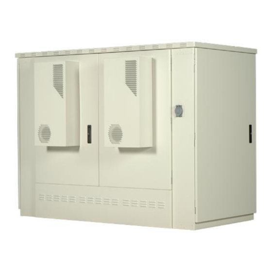
Chapter 1 ODC-3000 Product Overview This chapter provides a general description of the Calix ODC-3000 outdoor cabinet, including its standard features and options. Topics Covered This chapter covers the following topics: A description of the ODC-3000 cabinet. A list of cabinet features. -
Page 10: Cabinet Description
108 RU of mounting space. The hinged racks swing outward up to 90 degrees, providing easy rear access to the mounted equipment. The ODC-3000 houses up to four Calix C7 shelves, serving up to 1920 copper access lines or up to 8192 PON subscribers (32x split). -
Page 11: Cabinet Features
Redundant DC supplies to equipment (A and B) Low voltage DC disconnect (-42V) Up to 1020 Ah battery reserve capacity (NSB 170FT) Proprietary Information: Not for use or disclosure except by written agreement with Calix. © 2001-2008 Calix. All Rights Reserved. -
Page 12: Cabinet Options
Test head installation kits CWDM EDFA mounting kit (for FTTP RF video applications) Splitter shelves (1:32 PON or xDSL/POTS splitters) Proprietary Information: Not for use or disclosure except by written agreement with Calix. © 2001-2008 Calix. All Rights Reserved. -
Page 13: Cabinet Dimensions And Weights
The approximate shipping weight of the ODC-3000 cabinet is shown below. Configuration Weight (SAE) Weight (Metric) 1920 lines 2350 lb 1066 kg Proprietary Information: Not for use or disclosure except by written agreement with Calix. © 2001-2008 Calix. All Rights Reserved. -
Page 14: Cabinet Compartments
(47 inches/27 RU per bay) and typically houses two Valere power systems and up to four Calix C7 shelves, leaving 5 RU per bay of rack space for additional equipment. The swing frame rack design allows for easy access to the backside of the mounted equipment. - Page 15 ODC-3000 Rear Splice Compartments The ODC-3000 cabinet is equipped with two standard splice compartments: a fiber splice chamber (located on the right side of the cabinet when viewed from the front) and a copper splice chamber (located on the left side of the cabinet when viewed from the front). The fiber splice compartment is equipped with a standard 23-inch rack and houses the AC load center, main ground bar, and provides cable entry locations for fiber plant.
- Page 16 Zone 4 seismic protection kit. Battery Compartment (front) Battery Compartment (rear) Proprietary Information: Not for use or disclosure except by written agreement with Calix. © 2001-2008 Calix. All Rights Reserved.
-
Page 17: Chapter 2: Installation Considerations
Installation process overview Installation guidelines Space requirements General safety recommendations Installation kit contents User-supplied items Cabling requirements Proprietary Information: Not for use or disclosure except by written agreement with Calix. © 2001-2008 Calix. All Rights Reserved. -
Page 18: Installation Process Overview
Installation Process Overview The cabinet installation process involves the following high-level steps: Proprietary Information: Not for use or disclosure except by written agreement with Calix. © 2001-2008 Calix. All Rights Reserved. -
Page 19: Installation Guidelines
Conversely, wind exposure improves thermal conditions in a cabinet, so locations that do not block wind are desirable. Proprietary Information: Not for use or disclosure except by written agreement with Calix. © 2001-2008 Calix. All Rights Reserved. -
Page 20: Space Requirements
This area must be kept clear of obstructions at all times to provide adequate access for all installation and maintenance activities. Proprietary Information: Not for use or disclosure except by written agreement with Calix. © 2001-2008 Calix. All Rights Reserved. -
Page 21: General Safety Recommendations
ESD ALERT! Beware of electrostatic discharge. Follow standard ESD precautions. Always wear a grounded ESD wristband to avoid damaging the electronic equipment. Proprietary Information: Not for use or disclosure except by written agreement with Calix. © 2001-2008 Calix. All Rights Reserved. -
Page 22: Installation Kit
Installation Kit Calix supplies an installation kit with the cabinet that includes materials required for installation. The installation kit contents are listed below. Check to verify that your kit contains all of the listed items. Item Description Telco hex key, 5/16"... -
Page 23: User-Supplied Items
Five (5) connecting links or lifting hooks Four (4) shims Digital multi-meter Optical power meter Digital multi-function test set Proprietary Information: Not for use or disclosure except by written agreement with Calix. © 2001-2008 Calix. All Rights Reserved. -
Page 24: Cabling Requirements
LC, SC, ST, or FC (OSP splices/distribution) Note: Local climatic conditions, site conditions, or local practices may require adjustments to cabling requirements. Proprietary Information: Not for use or disclosure except by written agreement with Calix. © 2001-2008 Calix. All Rights Reserved. -
Page 25: Chapter 3: Preparing The Installation Site
Install the cabinet onto a concrete foundation pad. You can construct a concrete pad using the Calix cast-in-place template, or you can purchase a pre-cast concrete pad from a third-party supplier. For all mounting types, Calix requires installation of an earth ground circuit at the installation site to provide lightning protection. -
Page 26: Installing A Ground Circuit
Installing a Ground Circuit Calix requires installing an earth ground circuit (earth electrode) at the installation site to provide protection from electric shock for equipment and personnel. The ground circuit may consist of a simple copper rod driven into the earth or a complex system of buried rods and wires. - Page 27 Never bundle the ground wire together with other copper cables. Connect the ground wire to the main ground bar. Follow local code to satisfy additional requirements, if applicable. Proprietary Information: Not for use or disclosure except by written agreement with Calix. © 2001-2008 Calix. All Rights Reserved.
-
Page 28: Constructing A Concrete Pad
Construct the pad with a minimum height of 6 inches. Construct the pad with a maximum of 2 inches above-grade exposure. Use the Calix cast-in-place template to provide exact mounting stud and conduit locations. Use rebar or wire mesh inside the form to improve pad strength. - Page 29 Pad Drawings Use the following drawings for reference during pad construction. Pad Size Proprietary Information: Not for use or disclosure except by written agreement with Calix. © 2001-2008 Calix. All Rights Reserved.
- Page 30 Conduit for AC cable. Conduit Locations Use the Calix cast-in-place template to provide precise conduit orientation. Proprietary Information: Not for use or disclosure except by written agreement with Calix. © 2001-2008 Calix. All Rights Reserved.
-
Page 31: Assembling The Cast-In-Place Template
Place the two Splice brackets between (and perpendicular to) the Front and Rear brackets, with the entry boxes and labeled arrows (Splice) pointing toward the outside as shown. Proprietary Information: Not for use or disclosure except by written agreement with Calix. © 2001-2008 Calix. All Rights Reserved. - Page 32 4. Install the two support jacks into the threaded holes under the Front and Rear brackets as shown. 5. Tighten all screws to complete the template assembly. Proprietary Information: Not for use or disclosure except by written agreement with Calix. © 2001-2008 Calix. All Rights Reserved.
-
Page 33: Preparing The Site
3. Place and tie rebar inside the form elevated above the gravel. 4. Place the Calix cast-in-place template into the form, guiding the cable conduits through the conduit entry ducts in the template. -
Page 34: Casting The Pad
7. Backfill and grade the perimeter area around the pad with soil, as required. 8. Trim the cable conduits to a height no more than 4 inches above the pad. Proprietary Information: Not for use or disclosure except by written agreement with Calix. © 2001-2008 Calix. All Rights Reserved. -
Page 35: Installing A Pre-Cast Concrete Pad
Use 2-inch conduit (maximum) for AC cable. See drawing below for entry location. Include pull cords in all cable conduits. Refer to the pad manufacturer's instructions for additional guidelines. Proprietary Information: Not for use or disclosure except by written agreement with Calix. © 2001-2008 Calix. All Rights Reserved. - Page 36 Use the following drawings for reference during site preparation. Actual pad dimensions may vary by manufacturer. Refer to the manufacturer's documentation for more information. Typical Pad Size Proprietary Information: Not for use or disclosure except by written agreement with Calix. © 2001-2008 Calix. All Rights Reserved.
- Page 37 Conduit for fiber plant. c. Earth ground wire (preferred locations for direct connection to cabinet ground bars). d. Conduit for AC cable. Conduit Locations Proprietary Information: Not for use or disclosure except by written agreement with Calix. © 2001-2008 Calix. All Rights Reserved.
-
Page 38: Preparing The Site
6. Place gravel into the foundation hole to create a level base. The gravel layer should be at least two inches deep, compacted and leveled. Proprietary Information: Not for use or disclosure except by written agreement with Calix. © 2001-2008 Calix. All Rights Reserved. -
Page 39: Installing A Pre-Cast Pad
6. Backfill and grade around the pad perimeter with soil to secure the pad in place. 7. Verify that the pad remains level. Adjust as required. Proprietary Information: Not for use or disclosure except by written agreement with Calix. © 2001-2008 Calix. All Rights Reserved. - Page 40 Proprietary Information: Not for use or disclosure except by written agreement with Calix. © 2001-2008 Calix. All Rights Reserved.
-
Page 41: Chapter 4: Installing The Cabinet
Chapter 4 Installing the Cabinet This chapter describes how to install the Calix ODC-3000 cabinet onto a concrete foundation pad. Topics Covered This chapter covers the following topics: Unpacking the cabinet from its shipping crate. Operating the cabinet doors. -
Page 42: Unpacking The Cabinet
Doors (on page 43) for instructions. Note: Do not remove the bolts securing the cabinet to the pallet until the cabinet is ready for placement. Proprietary Information: Not for use or disclosure except by written agreement with Calix. © 2001-2008 Calix. All Rights Reserved. -
Page 43: Operating Cabinet Doors
5. When opening a door on a powered cabinet, pull the plunger on the alarm switch to disable reporting of the intrusion alarm. Note: Do not rotate the switch plunger. Rotating the plunger may damage the switch. Proprietary Information: Not for use or disclosure except by written agreement with Calix. © 2001-2008 Calix. All Rights Reserved. - Page 44 3. Insert the bolts (removed previously) through the matching holes in the door and cabinet and tighten using a 7/16-inch nut driver. Proprietary Information: Not for use or disclosure except by written agreement with Calix. © 2001-2008 Calix. All Rights Reserved.
-
Page 45: Preparing The Cabinet For Installation
(two in each splice compartment) plus two in the battery compartment (one in front, one in rear). Proprietary Information: Not for use or disclosure except by written agreement with Calix. © 2001-2008 Calix. All Rights Reserved. -
Page 46: Installing The Cabinet On A Concrete Pad
Use appropriately rated connecting links or lifting hooks. Calix recommends using at least three people to install the cabinet: one to operate the crane or derrick, one to guide the cabinet laterally as it lowers, and one to spot-check alignment of the mounting anchors/holes and the conduits/entry boxes as the cabinet lowers. - Page 47 Install one anchor bolt, square washer, and lock washer into each of the six threaded mounting inserts. c. Tighten the bolts to secure the cabinet to the pad. Proprietary Information: Not for use or disclosure except by written agreement with Calix. © 2001-2008 Calix. All Rights Reserved.
-
Page 48: Replacing The Lifting Eyebolts
2. Using a socket wrench, install a hex-head bolt into the vacant bolt hole. 3. Repeat Steps 1 and 2 to replace each additional lifting eyebolt on the cabinet roof, one at a time. Proprietary Information: Not for use or disclosure except by written agreement with Calix. © 2001-2008 Calix. All Rights Reserved. -
Page 49: Chapter 5: Installing Power
This chapter covers the following topics: Installing the cabinet ground connections. Installing the AC power supply (220–240 VAC standard). Proprietary Information: Not for use or disclosure except by written agreement with Calix. © 2001-2008 Calix. All Rights Reserved. -
Page 50: Installing The Cabinet Ground Connection
5. Attach the earth ground wire's two-hole lug onto the 3/4-inch ground terminal studs. 6. Re-connect the nuts to the ground terminal studs and tighten to 26 inch-lbs. of torque. Proprietary Information: Not for use or disclosure except by written agreement with Calix. © 2001-2008 Calix. All Rights Reserved. -
Page 51: Installing Ac Power (220-240 Vac)
Connect the red L2 lead to the right side of the Main Service Disconnect breaker. 9. Re-attach the Main Service Disconnect breaker into the load center. Proprietary Information: Not for use or disclosure except by written agreement with Calix. © 2001-2008 Calix. All Rights Reserved. - Page 52 10. Dress and secure the AC cable, providing adequate strain relief. 11. Replace the AC duct cover (two panels) and the left cover panel on the AC load center. Proprietary Information: Not for use or disclosure except by written agreement with Calix. © 2001-2008 Calix. All Rights Reserved.
-
Page 53: Chapter 6: Installing And Splicing Outside Plant Cables
Topics Covered This chapter covers the following topics: Installing fiber cable. Installing metallic cables. Sealing cable entry locations. Proprietary Information: Not for use or disclosure except by written agreement with Calix. © 2001-2008 Calix. All Rights Reserved. -
Page 54: Installing Fiber Cable
2. Strip off the cable's outer sheath to expose the core tubing. Take care not to damage the fibers inside the core tubing. Proprietary Information: Not for use or disclosure except by written agreement with Calix. © 2001-2008 Calix. All Rights Reserved. - Page 55 6. If splicing shall be performed at a later time, neatly coil the bare fibers inside the splice tray. Secure the core tubing to the rack with cable ties. Proprietary Information: Not for use or disclosure except by written agreement with Calix. © 2001-2008 Calix. All Rights Reserved.
-
Page 56: Splicing Fibers
Jumper splicing: Splice OSP fibers directly to jumpers that connect to the optical equipment, bypassing any intermediate patch panels. Both splicing methods typically use a fiber splice tray to hold the individual splices. Calix offers splice tray options with fusion, heat shrink, and mechanical splicing options. Each splice tray can hold up to 12 fiber splices. -
Page 57: Routing And Terminating Fibers
With the jumper splicing method, you typically route jumpers from the splice tray directly to the optical equipment. No intermediate patch panel is typically used. Route and terminate fibers per your application requirements and local practice. Calix offers optional fiber distribution systems, including a 24-position distribution panel or a distribution cassette holder with up to six 12-position cassettes. -
Page 58: Installing Metallic Cables
Install a B-bond clamp onto the cut end of the OSP cable's outer sheath. Wrap the connection with electrical tape. b. Attach a #6 AWG bond strap to the B-bond clamp. Proprietary Information: Not for use or disclosure except by written agreement with Calix. © 2001-2008 Calix. All Rights Reserved. - Page 59 7. If splicing shall be performed at a later time, make sure cable arrangement allows the door to close. Take care to not violate the cable bend radius requirements. Proprietary Information: Not for use or disclosure except by written agreement with Calix. © 2001-2008 Calix. All Rights Reserved.
-
Page 60: Splicing Metallic Cables
6. Repeat Steps 2 through 5 for each remaining OSP cable. 7. Dress and secure the spliced cables to the rack or tie bars with cable ties. Proprietary Information: Not for use or disclosure except by written agreement with Calix. © 2001-2008 Calix. All Rights Reserved. -
Page 61: Applying T1 Labels To Protection Blocks
Find the factory label for the half of the block that protects the identified slot. 4. Apply the appropriately-numbered red T1 label over the factory label on the identified protection block. Proprietary Information: Not for use or disclosure except by written agreement with Calix. © 2001-2008 Calix. All Rights Reserved. -
Page 62: Installing 5-Pin Protection Modules
Use black modules for T0 circuits and red modules for T1 circuits. Refer to the cabinet pair assignment list for more information. Proprietary Information: Not for use or disclosure except by written agreement with Calix. © 2001-2008 Calix. All Rights Reserved. -
Page 63: Sealing Cable Entry Locations
CAUTION! Check to ensure that all gaps are completely sealed. Gaps allow penetration of moisture, insects, rodents, and other contaminants that could damage equipment. Proprietary Information: Not for use or disclosure except by written agreement with Calix. © 2001-2008 Calix. All Rights Reserved. - Page 64 Proprietary Information: Not for use or disclosure except by written agreement with Calix. © 2001-2008 Calix. All Rights Reserved.
-
Page 65: Chapter 7: Turning Up The Cabinet Power System
Installing rectifier modules into the Valere power shelf. Installing batteries for reserve power. Turning up and testing the DC power system. Proprietary Information: Not for use or disclosure except by written agreement with Calix. © 2001-2008 Calix. All Rights Reserved. -
Page 66: Checking The Ground Connection
3. If the reading is greater than 5 ohms, check the ground wire connection at the main ground bar, then retest. Proprietary Information: Not for use or disclosure except by written agreement with Calix. © 2001-2008 Calix. All Rights Reserved. -
Page 67: Checking The Ac Power Supply Voltage
Note: Do not switch the Rectifier A and Rectifier B breakers on at this time. 7. Re-attach the left and right cover panels on the AC load center. Proprietary Information: Not for use or disclosure except by written agreement with Calix. © 2001-2008 Calix. All Rights Reserved. -
Page 68: Installing Rectifier Modules Into The Valere Power Shelf
Each Valere power shelf supports up to four rectifier modules (20A or 30A options). Normal operation for the ODC-3000 cabinet requires a minimum of two rectifier modules per Valere shelf (one module per supported C7 shelf). Use additional rectifier modules to support high- loaded systems, provide module redundancy, faster battery charging time, or powering for third-party equipment. - Page 69 6. Repeat Steps 1–5 to install additional rectifier modules. Refer to the Valere Compact DC Power System Installation and Maintenance manual for more information. Proprietary Information: Not for use or disclosure except by written agreement with Calix. © 2001-2008 Calix. All Rights Reserved.
-
Page 70: Installing Batteries
Installing Batteries The ODC-3000 cabinet can house up to six strings of front terminal batteries (four batteries per string). See Supported Batteries (on page 121) for a list of supported battery types. WARNING! Electrical hazard. Batteries contain a stored charge. Only a qualified technician should perform this procedure. - Page 71 Attach the red cable to the negative (-) terminal post at the negative end of the string. d. Tighten the nuts on the terminal posts to the torque specified by the manufacturer. Proprietary Information: Not for use or disclosure except by written agreement with Calix. © 2001-2008 Calix. All Rights Reserved.
- Page 72 See Installing a Seismic Protection Kit for instructions. 10. Replace the front and rear battery compartment doors. See Operating Cabinet Doors (on page 43) for instructions. Proprietary Information: Not for use or disclosure except by written agreement with Calix. © 2001-2008 Calix. All Rights Reserved.
-
Page 73: Turning Up And Testing The Dc Power System
(if internal temperature is high enough). 6. At each DC distribution panel, switch the four 30A C7 load breakers ON. Proprietary Information: Not for use or disclosure except by written agreement with Calix. © 2001-2008 Calix. All Rights Reserved. - Page 74 5. At the AC load center, set the Main breaker to ON and verify that power restores to the Valere shelf. Proprietary Information: Not for use or disclosure except by written agreement with Calix. © 2001-2008 Calix. All Rights Reserved.
-
Page 75: Chapter 8: Installing Equipment And Adding Capacity
See Removing the Air Plenum Cover (on page 102) for instructions. Proprietary Information: Not for use or disclosure except by written agreement with Calix. © 2001-2008 Calix. All Rights Reserved. -
Page 76: Installing A C7 Expansion Shelf
Installing an expansion shelf does not affect services on the existing equipment. WARNING! Electrical hazard. Only a qualified technician should perform this task. Proprietary Information: Not for use or disclosure except by written agreement with Calix. © 2001-2008 Calix. All Rights Reserved. - Page 77 At the DC distribution panel above, switch OFF the two 30A C7 load breakers for the new shelf. WARNING! Risk of electric shock. Follow all safety precautions and use insulated tools when working with power. Proprietary Information: Not for use or disclosure except by written agreement with Calix. © 2001-2008 Calix. All Rights Reserved.
- Page 78 On the C7 shelf above the expansion shelf, connect the MTA cable's FAC OUT end to the A FAC OUT wire-wrap pins on the AIM board (black to Tip, white to Ring). Proprietary Information: Not for use or disclosure except by written agreement with Calix. © 2001-2008 Calix. All Rights Reserved.
- Page 79 4. Use cable ties to dress and secure the cables to the shelf on the hinged side of the rack. Proprietary Information: Not for use or disclosure except by written agreement with Calix. © 2001-2008 Calix. All Rights Reserved.
-
Page 80: Installing A C7 Fan Tray
Installing a C7 Fan Tray Each Calix C7 shelf requires a fan tray mounted underneath it for shelf cooling. Fan trays do not ship installed. Install the fan tray(s) as described below. The front panel of the C7 fan tray shows the results of a power test at start-up. -
Page 81: Installing A Protection Mounting Frame
4. Route the two frame ground wires to the main ground bar (located at the bottom of the splice compartment). Attach the ground wire lugs to any open position on the main ground bar. Proprietary Information: Not for use or disclosure except by written agreement with Calix. © 2001-2008 Calix. All Rights Reserved. -
Page 82: Installing A Protection Block
Fasten the protection block to the mounting frame using two supplied screws. Note: The screws provide a critical ground path through the mounting frame to the cabinet's main ground bar. Proprietary Information: Not for use or disclosure except by written agreement with Calix. © 2001-2008 Calix. All Rights Reserved. - Page 83 8. Secure the protection block interface cables to the rack or towel bars with cable ties as needed. Proprietary Information: Not for use or disclosure except by written agreement with Calix. © 2001-2008 Calix. All Rights Reserved.
-
Page 84: Installing A Battery Heater
Installing a Battery Heater For colder climates, Calix recommends using an optional battery heater to prevent batteries from freezing and to prolong battery life. The cabinet supports up to three battery heaters, with each heater supporting two battery strings (front to back). The battery heater is controlled by a thermostat set for the following operation: ... -
Page 85: Installing A Seismic Protection Kit
Position the rear bracket against the rear mounting rack, with the recessed section toward the back as shown. b. Attach the bracket to the rack using six self-tapping screws from the installation kit. Proprietary Information: Not for use or disclosure except by written agreement with Calix. © 2001-2008 Calix. All Rights Reserved. - Page 86 Position the front bracket against the front mounting rack, encompassing the batteries as shown. b. Attach the bracket to the rack using four self-tapping screws. Proprietary Information: Not for use or disclosure except by written agreement with Calix. © 2001-2008 Calix. All Rights Reserved.
- Page 87 Attach the bracket to the rack using two self-tapping screws. 8. Repeat Steps 3 through 7 to install additional seismic protection kits (one per battery string). Proprietary Information: Not for use or disclosure except by written agreement with Calix. © 2001-2008 Calix. All Rights Reserved.
-
Page 88: Installing An Ac Meter
AC meter. Follow NEC and local codes when handling power systems. The figure below shows the suggested mounting location for a single position, 4-terminal, ring-type outdoor AC power meter: Proprietary Information: Not for use or disclosure except by written agreement with Calix. © 2001-2008 Calix. All Rights Reserved. -
Page 89: Installing A Generator Connector
At the exterior front of the cabinet, remove the blank plate from the cabinet wall to expose the connector mounting fixture. Proprietary Information: Not for use or disclosure except by written agreement with Calix. © 2001-2008 Calix. All Rights Reserved. - Page 90 100A models: Install four mounting screws into the four mounting holes (threaded inserts). Tighten the screws to secure the generator connector assembly in place. 30A model Proprietary Information: Not for use or disclosure except by written agreement with Calix. © 2001-2008 Calix. All Rights Reserved.
- Page 91 6. At the AC load center, switch all breakers to ON. 7. At the local power transfer switch, restore AC power to the cabinet. Proprietary Information: Not for use or disclosure except by written agreement with Calix. © 2001-2008 Calix. All Rights Reserved.
-
Page 92: Installing A Heat Exchanger Door
2. Install the new heat exchanger door on the vacant door frame. See Installing a Cabinet Door (on page 110) for instructions. Proprietary Information: Not for use or disclosure except by written agreement with Calix. © 2001-2008 Calix. All Rights Reserved. -
Page 93: Installing A Fiber Splice Tray Holder
Secure the routing conduit to the bracket by wrapping the velcro strap around the conduit and through the horizontal cutouts in the bracket as shown. Proprietary Information: Not for use or disclosure except by written agreement with Calix. © 2001-2008 Calix. All Rights Reserved. - Page 94 4. Route the fiber pigtails from the splice tray through the fiber routing conduit to the distribution system or the equipment. Proprietary Information: Not for use or disclosure except by written agreement with Calix. © 2001-2008 Calix. All Rights Reserved.
-
Page 95: Installing A Fiber Distribution Panel
Remove the rubber dust caps from the front bulkhead adapters, if present. b. Insert the fiber jumpers into any available adapter positions on the front panel. Proprietary Information: Not for use or disclosure except by written agreement with Calix. © 2001-2008 Calix. All Rights Reserved. -
Page 96: Installing A Fiber Distribution Cassette Holder
4. Position the cassette holder against rack in the identified location, oriented with the swivel side of the holder on the left. Attach the distribution panel to the rack using six supplied self-tapping screws. Proprietary Information: Not for use or disclosure except by written agreement with Calix. © 2001-2008 Calix. All Rights Reserved. - Page 97 Route the fiber jumpers to the equipment. Dress and secure the jumpers as required. 7. Push (rotate) the cassette holder back against the bracket. Proprietary Information: Not for use or disclosure except by written agreement with Calix. © 2001-2008 Calix. All Rights Reserved.
-
Page 98: Installing An Xdsl Splitter Shelf
The cabinet supports third-party xDSL splitters to separate POTS and DSL signals from subscriber lines within the enclosure. Splitter shelves employ passive filters that require no power to operate. Calix provides two ADSL splitter shelf options that use a common 24-port splitter card: ... - Page 99 ADSL card. b. Connect the POTS overlay cable's "PSTN IN" end to the MS connector from the outside plant overlay cable. Proprietary Information: Not for use or disclosure except by written agreement with Calix. © 2001-2008 Calix. All Rights Reserved.
- Page 100 5. Repeat Steps 2 through 4 to install additional cards in the splitter shelf as required. 6. Re-install the front cover panel on the splitter shelf. Proprietary Information: Not for use or disclosure except by written agreement with Calix. © 2001-2008 Calix. All Rights Reserved.
-
Page 101: Installing A Pon Splitter Kit
Installing a PON Splitter Kit To support passive fiber splitting within the enclosure, the ODC-3000 can house up to twelve 96-line (3 x 1:32) PON splitter kits, arranged as shown. ODC-3000 Rear For installation instructions, see the Calix ODC PON Splitter Kit Installation Guide. -
Page 102: Removing The Rear Air Plenum Covers
4. Lift the cover away from the plenum, taking care to disengage the two tabs on the cover from the corresponding slots in the plenum. 5. Discard the plenum cover or set it aside for future reuse. Proprietary Information: Not for use or disclosure except by written agreement with Calix. © 2001-2008 Calix. All Rights Reserved. -
Page 103: Chapter 9: Cabinet Maintenance
Topics Covered This chapter covers the following topics: Routine cabinet maintenance Replacing parts and equipment Proprietary Information: Not for use or disclosure except by written agreement with Calix. © 2001-2008 Calix. All Rights Reserved. -
Page 104: Routine Maintenance
Remove the jumper straps from between the terminals of batteries in the string. e. Slide the batteries out of the battery compartment. Proprietary Information: Not for use or disclosure except by written agreement with Calix. © 2001-2008 Calix. All Rights Reserved. - Page 105 7. Re-install the batteries into the battery compartment. See Installing Batteries for instructions. Proprietary Information: Not for use or disclosure except by written agreement with Calix. © 2001-2008 Calix. All Rights Reserved.
-
Page 106: Checking Electrical Components
Note any damage to the metal work. If the damaged area interferes with operation of the cabinet or electronics, contact Calix support for assistance with a resolution. Repair damage to the paint using touch-up paint available from Calix after cleaning the surface and removing rust. -
Page 107: Checking Cable Connections
Check all conduits to ensure that any material used to seal between the cable and the conduit is still present and providing a complete seal. Proprietary Information: Not for use or disclosure except by written agreement with Calix. © 2001-2008 Calix. All Rights Reserved. -
Page 108: Replacing Parts And Equipment
3. Remove the nut, bolt, and washer fastening the wind brace to the bracket inside the door frame. Proprietary Information: Not for use or disclosure except by written agreement with Calix. © 2001-2008 Calix. All Rights Reserved. - Page 109 Bottom hinge: Lift up on the pin lever until the pin slides free from the channel. 6. Lift the door away from the cabinet. Proprietary Information: Not for use or disclosure except by written agreement with Calix. © 2001-2008 Calix. All Rights Reserved.
-
Page 110: Installing A Cabinet Door
Bottom hinge: Press down on the pin lever until the pin slides completely into the pin channel. c. Rotate the pin levers into the cradles to secure the hinges. Proprietary Information: Not for use or disclosure except by written agreement with Calix. © 2001-2008 Calix. All Rights Reserved. - Page 111 Route the power cable to the DC distribution panel and connect it to GMT terminal position HX Front or HX Rear. Proprietary Information: Not for use or disclosure except by written agreement with Calix. © 2001-2008 Calix. All Rights Reserved.
-
Page 112: Replacing Ac Breakers
8. At the AC load center, switch all breakers to ON. 9. At the local power transfer switch, restore AC power to the cabinet. Proprietary Information: Not for use or disclosure except by written agreement with Calix. © 2001-2008 Calix. All Rights Reserved. -
Page 113: Replacing Dc Breakers And Fuses
4. Install the new breaker into the vacated housing position. 5. Replace the cover on the DC distribution panel. Proprietary Information: Not for use or disclosure except by written agreement with Calix. © 2001-2008 Calix. All Rights Reserved. -
Page 114: Replacing Rectifier Modules
Valere shelf. Note: If the Valere shelf is not equipped with a redundant rectifier module, and the load is heavy, Calix recommends temporarily installing an additional module into the shelf to carry the load while you replace the failed module. - Page 115 Note: For detailed instructions on controller functionality, including how to program the controller module, see the Valere Compact DC Power System Installation and Maintenance manual. Proprietary Information: Not for use or disclosure except by written agreement with Calix. © 2001-2008 Calix. All Rights Reserved.
-
Page 116: Replacing Batteries
If a battery or string of batteries fails, becomes damaged, or wears out its life, you can replace the battery or string as described below. Replacing batteries does not impact cabinet service, provided that an AC power failure does not occur during the replacement process. Calix recommends connecting an external generator to the cabinet while performing battery maintenance to ensure service continuity in the event of an AC outage. -
Page 117: Replacing A Battery Heater
5. Install the new battery heater into the battery compartment and connect it power cord to the AC outlet. See Installing a Battery Heater for instructions. 6. Reload and reconnect batteries. See Installing Batteries for instructions. Proprietary Information: Not for use or disclosure except by written agreement with Calix. © 2001-2008 Calix. All Rights Reserved. - Page 118 Proprietary Information: Not for use or disclosure except by written agreement with Calix. © 2001-2008 Calix. All Rights Reserved.
-
Page 119: Appendix A: Reference Information
Valere rectifier settings (battery profiles) Programming instructions for the Valere shelf controller module Rectifier module usage guidelines Cabinet wiring diagrams Proprietary Information: Not for use or disclosure except by written agreement with Calix. © 2001-2008 Calix. All Rights Reserved. -
Page 120: Specifications
UL 60950 CAN/CSA-C22.2 No. 60950 FCC Part 15, Class A ICES-003, Class A Telcordia GR-487-CORE, Issue 2 GR-63-CORE, Issue 1 (NEBS) Proprietary Information: Not for use or disclosure except by written agreement with Calix. © 2001-2008 Calix. All Rights Reserved. -
Page 121: Supported Batteries
Supported Batteries The ODC-3000 supports the following batteries. For a list of battery distributors, contact your sales representative. Manufacturer Model Capacity (Ah) Max # of per String Strings Northstar NSB 170FT 170 Ah Fiamm 12FAT 155 155 Ah GNB Marathon... -
Page 122: Environmental Alarm Mapping (To C7)
Environmental Alarm Mapping (to C7) Environmental alarms in the ODC-2000 cabinet map to the C7 Alarm Interface Module (AIM) board, located on the back of the Calix C7 shelf. The table below lists the pinout assignments for environmental alarms. AIM BOARD... -
Page 123: Valere Rectifier Alarm Matrix
Current Share Single Rectifier Failure Multiple Rectifier Failure System Communication High Temperature Thermal Runaway (if T Comp is enabled) Battery Test Failure Proprietary Information: Not for use or disclosure except by written agreement with Calix. © 2001-2008 Calix. All Rights Reserved. -
Page 124: Valere Rectifier Setpoints
Lo Temp Thermal Comp The controller begins to reduce the float voltage 10.0 Start Temp when the highest measured battery temperature reaches this value Proprietary Information: Not for use or disclosure except by written agreement with Calix. © 2001-2008 Calix. All Rights Reserved. - Page 125 2 deg C below threshold. High Temperature Alarm The temperature (deg C) below which the High Release Temperature Alarm clears. Proprietary Information: Not for use or disclosure except by written agreement with Calix. © 2001-2008 Calix. All Rights Reserved.
-
Page 126: Programming The Valere Shelf Controller
(VRLA or LMP) for the type of battery used in the cabinet. For a list of the default profile settings, see Valere Rectifier Setpoints (on page 124). Proprietary Information: Not for use or disclosure except by written agreement with Calix. © 2001-2008 Calix. All Rights Reserved. - Page 127 3. Modify the settings per your application requirements. 4. Press the UP button until >EXIT SETPOINT displays. Press the MENU button to exit. Proprietary Information: Not for use or disclosure except by written agreement with Calix. © 2001-2008 Calix. All Rights Reserved.
-
Page 128: Rectifier Module Usage Guidelines
1782W to 2364W 2364W to 3564W Calix recommends using an N+1 rectifier module scheme for redundancy. The quantity shown represents N only, with no redundant module. Note: When using 20A rectifier modules, loads greater than 3564W per power shelf require 4 modules, prohibiting N+1 module redundancy. - Page 129 The maximum power values shown include a per-C7 minimum power load of 330 W, consisting of two RAP-OCn (2 x 65W), one AMP (10W), one fan tray (70W), and one heat exchanger (120 W). Calix recommends using an N+1 rectifier module scheme for redundancy. The quantity shown represents N only, with no redundant module.
- Page 130 The maximum power values shown include a per-C7 minimum power load of 330 W, consisting of two RAP-OCn (2 x 65W), one AMP (10W), one fan tray (70W), and one heat exchanger (120 W). Calix recommends using an N+1 rectifier module scheme for redundancy. The quantity shown represents N only, with no redundant module.
-
Page 131: Wiring Diagrams
Wiring Diagrams This section contains wiring diagrams of the ODC-3000 cabinet power, ground, and alarm systems. Wiring diagrams are shown for reference only. For better detail, see the full B-sized (11" x 17") wiring diagrams included in the binder that ships with the cabinet. -
Page 132: Ac Wiring (220-240 Vac)
AC Wiring (220-240 VAC) Proprietary Information: Not for use or disclosure except by written agreement with Calix. © 2001-2008 Calix. All Rights Reserved. -
Page 133: Dc Wiring
DC Wiring Proprietary Information: Not for use or disclosure except by written agreement with Calix. © 2001-2008 Calix. All Rights Reserved. -
Page 134: Ground Wiring
Ground Wiring Proprietary Information: Not for use or disclosure except by written agreement with Calix. © 2001-2008 Calix. All Rights Reserved. -
Page 135: Alarm Wiring
Alarm Wiring Proprietary Information: Not for use or disclosure except by written agreement with Calix. © 2001-2008 Calix. All Rights Reserved. - Page 136 Proprietary Information: Not for use or disclosure except by written agreement with Calix. © 2001-2008 Calix. All Rights Reserved.
Need help?
Do you have a question about the ODC-3000 and is the answer not in the manual?
Questions and answers