Table of Contents
Advertisement
Quick Links
Advertisement
Table of Contents

Subscribe to Our Youtube Channel
Related Manuals for Aerotech AOM360D Series


Summary of Contents for Aerotech AOM360D Series
-
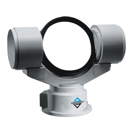
Page 1: Aom360D Direct-Drive Gimbal User Manual
AOM360D Direct-Drive Gimbal User Manual Revision: 1.02.00... - Page 2 This manual contains proprietary information and may not be reproduced, disclosed, or used in whole or in part without the express written permission of Aerotech, Inc. Product names mentioned herein are used for identification purposes only and may be trademarks of their respective companies.
-
Page 3: Table Of Contents
3.3. Stage Hall, Thermistor, Inductosyn, and Limits Specifications 3.4. Limits, Marker, and Machine Direction 3.5. Motor and Feedback Phasing Chapter 4: Maintenance 4.1. Service and Inspection Schedule 4.2. Cleaning and Lubrication Appendix A: Warranty and Field Service Appendix B: Revision History Index www.aerotech.com... -
Page 4: List Of Figures
Leveling Screw Assembly Figure 3-1: Motor Wiring [AZ and EL] Figure 3-2: Feedback Wiring [AZ and EL] Figure 3-3: Machine Direction Figure 3-4: Hall Phasing Figure 3-5: Analog Encoder Phasing Reference Diagram Figure 3-6: Encoder Phasing Reference Diagram (Standard) www.aerotech.com... -
Page 5: List Of Tables
List of Tables Table 1-1: AOM360D Optical Mount Model Options Table 1-2: Environmental Specifications Table 1-3: AOM360D Series Specifications Table 3-1: 26-Pin Motor Connector Pinouts [AZ and EL] Table 3-2: 26-Pin Motor Connector Mating Connector Table 3-3: 19-Pin Feedback Connector Pinouts [AZ and EL]... -
Page 6: Safety Procedures And Warnings
N O T E : Aerotech continually improves its product offerings; listed options may be superseded at any time. All drawings and illustrations are for reference only and were complete and accurate as of this manual’s release. -
Page 7: Eu Declaration Of Incorporation
AOM360D User Manual Table of Contents EU Declaration of Incorporation Manufacturer: Aerotech, Inc. 101 Zeta Drive Pittsburgh, PA 15238-2811 herewith declares that the product: AOM360D is intended to be incorporated into machinery to constitute machinery covered by the Directive 2006/42/EC as amended;... - Page 8 Table of Contents AOM360D User Manual This page intentionally left blank. www.aerotech.com...
-
Page 9: Chapter 1: Overview
Overview Chapter 1: Overview Table 1-1: AOM360D Optical Mount Model Options AOM360D Optical Mount Cell Size (Required) -200 200 mm diameter cell -300 300 mm diameter cell -400 400 mm diameter cell -500 500 mm diameter cell www.aerotech.com Chapter 1... -
Page 10: Environmental Specifications
Indoor use only 1.2. Accuracy and Temperature Effects Aerotech products are designed for and built in a 20°C (68°F) environment. Extreme temperature changes could cause a decrease in performance or permanent damage to the AOM360D. At a minimum, the environmental temperature must be controlled to within 0.25ºC per 24 hours to ensure the AOM360D specifications are repeatable over an extended period of time. -
Page 11: Basic Specifications
Paint: Textured Epoxy (Polane-T), Pebble Grey Color 1. Special cell adapters and slip ring assemblies available by special order. 2. Requires Aerotech controls and axis calibration. 3. Maximum speed based on stage capability. Maximum application velocity may be limited by system data rate and system resolution. -
Page 12: Vacuum Operation
The AOM360D is export controlled by United States Commerce Department export regulations. If you are from a non-US country and wish to purchase this gimbal, contact Aerotech to determine if an export license is required to purchase this product. People in countries embargoed by the United States cannot purchase and import this product. -
Page 13: Chapter 2: Mechanical Specifications And Installation
Aerotech. Use compressed nitrogen or clean, dry, oil-less air to remove any dust or debris that has collected during shipping. Set the AOM360D on a smooth, flat, and clean surface. -
Page 14: Dimensions
Mechanical Installation AOM360D User Manual 2.2. Dimensions Figure 2-1: AOM360D-200 Dimensions Chapter 2 www.aerotech.com... -
Page 15: Figure 2-2: Aom360D-300 Dimensions
AOM360D User Manual Mechanical Installation Figure 2-2: AOM360D-300 Dimensions www.aerotech.com Chapter 2... -
Page 16: Figure 2-3: Aom360D-400 Dimensions
Mechanical Installation AOM360D User Manual Figure 2-3: AOM360D-400 Dimensions Chapter 2 www.aerotech.com... -
Page 17: Figure 2-4: Aom360D-500 Dimensions
AOM360D User Manual Mechanical Installation Figure 2-4: AOM360D-500 Dimensions www.aerotech.com Chapter 2... -
Page 18: Securing The Aom360D Base To The Mounting Surface
If machining is required to achieve the desired flatness, it should be performed on the mounting surface rather than the AOM360D. Shimming should be avoided if possible. If shimming is required, it should be minimized to retain maximum rigidity of the system. Chapter 2 www.aerotech.com... -
Page 19: Figure 2-5: Mounting Hole Locations
2. Loosen the jam nut with a 1 1/4" wrench. 3. Adjust the height with a 1" wrench on the adjustment hex. The rate of displacement is approximately 0.032" per CW turn. 4. Tighten the jam nut. 5. Tighten the SHCS to 58 Ft–Lbs. www.aerotech.com Chapter 2... -
Page 20: Figure 2-6: Leveling Screw Assembly
Mechanical Installation AOM360D User Manual Figure 2-6: Leveling Screw Assembly Chapter 2 www.aerotech.com... -
Page 21: Attaching The Payload To The Stage
Inspect the mounting surface for dirt or unwanted residue and clean if necessary. Clean the mounting surface with a lint free cloth and isopropyl alcohol and allow the cleaning solvent to completely dry. The payload must be flat, rigid, and comparable to the stage in quality to maintain optimum performance. www.aerotech.com Chapter 2... - Page 22 Mechanical Installation AOM360D User Manual This page intentionally left blank. Chapter 2 www.aerotech.com...
-
Page 23: Chapter 3: Electrical Specifications And Installation
Aerotech motion control systems are adjusted at the factory for optimum performance. When the AOM360D is part of a complete Aerotech motion control system, setup usually involves connecting a stage to the appropriate drive chassis with the cables provided. Labels on the system components usually indicate the appropriate connections. -
Page 24: Motor And Feedback Connectors
Stages equipped with standard motors and encoders come from the factory completely wired and assembled. N O T E : Refer to the other documentation accompanying your Aerotech equipment. Call your Aerotech representative if there are any questions on system configuration. -
Page 25: Table 3-1: 26-Pin Motor Connector Pinouts [Az And El]
Over-Temperature Thermistor sensor Home limit (connected internally to Pin-S; with Home limit option only) Signal Shield Motor Shield Table 3-2: 26-Pin Motor Connector Mating Connector Mating Connector Aerotech P/N Third Party P/N Connector ECK00622 ITT Cannon, KPT06J16-26S www.aerotech.com Chapter 3... -
Page 26: Table 3-3: 19-Pin Feedback Connector Pinouts [Az And El]
Supply common ground -12 V supply input Reserved Signal-2/Signal-4 Shield Signal 4 Sine Shield Sine - REF- Ref Shield Table 3-4: 19-Pin Feedback Connector Mating Connector Mating Connector Aerotech P/N Third Party P/N Connector ECK00619 ITT Cannon, KPT06J14-19S Chapter 3 www.aerotech.com... -
Page 27: Motor And Feedback Wiring
All motor and controller manufacturers have their own designations for motor phases A/B/C and Hall signals A/B/C (refer to Section 3.5. for motor phasing). Shielded cables are required for the motor and feedback connections. Figure 3-1: Motor Wiring [AZ and EL] www.aerotech.com Chapter 3... -
Page 28: Figure 3-2: Feedback Wiring [Az And El]
Electrical Installation AOM360D User Manual Figure 3-2: Feedback Wiring [AZ and EL] Chapter 3 www.aerotech.com... -
Page 29: Stage Hall, Thermistor, Inductosyn, And Limits Specifications
Output Current 10 mA (sinking) Normally Closed (NC) Sinks current to ground (Logic "0") when not in limit Output Polarity High impedance (Logic "1") when in limit (Factory Configured) Requires external pull-up to +5 V (10 kΩ recommended) www.aerotech.com Chapter 3... -
Page 30: Table 3-6: S-180-44 [El] And S-180-69 [Az] Rotary Motor Specifications (-200 And -300 Options)
6. Specifications given are for the motor only. When integrated into a housing with bearings additional losses should be considered. 7. Maximum winding temperature is 100 °C (thermistor trips at 100 °C) 8. Ambient operating temperature range 0 °C - 25 °C; consult Aerotech for performance in elevated ambient temperatures 9. All Aerotech amplifiers are rated A ;... -
Page 31: Table 3-7: S-240-63 [El] And S-240-83 [Az] Rotary Motor Specifications (-400 And -500 Options)
6. Specifications given are for the motor only. When integrated into a housing with bearings additional losses should be considered. 7. Maximum winding temperature is 100 °C (thermistor trips at 100 °C) 8. Ambient operating temperature range 0 °C - 25 °C; consult Aerotech for performance in elevated ambient temperatures 9. All Aerotech amplifiers are rated A ;... -
Page 32: Limits, Marker, And Machine Direction
AOM360D User Manual 3.4. Limits, Marker, and Machine Direction Aerotech stages are configured to have positive and negative "machine" directions. The machine direction defines the phasing of the feedback and motor signals and is dictated by the stage wiring (refer to Section 3.5. -
Page 33: Motor And Feedback Phasing
AOM360D User Manual Electrical Installation 3.5. Motor and Feedback Phasing Motor phase voltage is measured relative to the virtual wye common point. Figure 3-4: Hall Phasing www.aerotech.com Chapter 3... -
Page 34: Figure 3-5: Analog Encoder Phasing Reference Diagram
Electrical Installation AOM360D User Manual Figure 3-5: Analog Encoder Phasing Reference Diagram Figure 3-6: Encoder Phasing Reference Diagram (Standard) Chapter 3 www.aerotech.com... -
Page 35: Chapter 4: Maintenance
Re-tighten loose connectors. Replace or repair damaged cables. Clean the AOM360D and any components and cables as needed. Repair any damage before operating the AOM360D. Inspect and perform an operational check on all safeguards and protective devices. www.aerotech.com Chapter 4... -
Page 36: Cleaning And Lubrication
Any external metal surface of the AOM360D can be cleaned with isopropyl alcohol on a lint-free cloth. W A R N I N G : Make sure that all solvent has completely evaporated before attempting to move the stage. Lubrication There are no elements on AOM360D stages that require lubrication. Chapter 4 www.aerotech.com... -
Page 37: Appendix A: Warranty And Field Service
Aerotech makes no warranty that its products are fit for the use or purpose to which they may be put by the buyer, whether or not such use or purpose has been disclosed to Aerotech in specifications or drawings previously or subsequently provided, or whether or not Aerotech’s... - Page 38 Aerotech's approval. On-site Warranty Repair If an Aerotech product cannot be made functional by telephone assistance or by sending and having the customer install replacement parts, and cannot be returned to the Aerotech service center for repair, and if Aerotech determines the problem could be warranty-related, then the following policy applies:...
-
Page 39: Appendix B: Revision History
Updated Sections: Safety Procedures and Warnings Overview Section 2.2. Dimensions 1.02.00 Added Sections: EU Declaration of Incorporation Section 3.1. Motor and Feedback Connectors Section 3.3. Stage Hall, Thermistor, Inductosyn, and Limits Specifications 1.01.00 Product update 1.00.00 New Manual www.aerotech.com Appendix B... - Page 40 Revision History AOM360D User Manual This page intentionally left blank. Appendix B www.aerotech.com...
-
Page 41: Index
Performance Specifications serial number Global Technical Support shimming grease shipping clamps solvents Hall-Effect Sensors Specifications stage distortion Humidity Support inspection schedule Technical Support Inspection Schedule Thermistor Specifications isopropyl alcohol vacuum guidelines label Lifting Instructions Warranty and Field Service www.aerotech.com Index... - Page 42 Index AOM360D User Manual This page intentionally left blank. Index www.aerotech.com...
Need help?
Do you have a question about the AOM360D Series and is the answer not in the manual?
Questions and answers