
Summary of Contents for Infinite TRANSTECTOR TT-DT10-2G-8GP+
- Page 1 8-Port 10/100/1000T 802.3at PoE + 2-Port 10/100/1000T Desktop Switch Model: TT-DT10-2G-8GP+ User's Manual...
- Page 2 FCC Warning This equipment has been tested and found to comply with the limits for a Class A digital device, pursuant to Part 15 of the FCC Rules. These limits are designed to provide reasonable protection against harmful inter- ference when the equipment is operated in a commercial environment. This equipment generates, uses, and can radiate radio frequency energy and, if not installed and used in accordance with the Instruction manual, may cause harmful interference to radio communications.
-
Page 3: Table Of Contents
TABLE OF CONTENTS 1. INTRODUCTION......................4 1.1 C ..............................4 HECKLIST 1.2 P ..........................4 RODUCT ESCRIPTION 1.3 F ..............................5 EATURES 1.4 S ............................6 PECIFICATIONS 2. HARDWARE DESCRIPTION ..................8 2.1 F ............................8 RONT ANEL 2.2 R ............................ -
Page 4: Introduction
Chapter 1. Introduction 1.1 Checklist Check the contents of your package for the following parts: GSD-1008HP x 1 Screws Package x 1 Power Cord x 1 Rubber Feet x 4 Rack-mounting Brackets x 2 1.2 Product Description To fulfill the demand of sufficient PoE power for network applications with Gigabit speed transmission, TT-DT10-2G-8GP+ 8-Port 10/100/1000T 802.3at PoE + 2-Port 10/100/1000T Desktop Switch, features up to 30 watts of power output for each port and a total PoE budget of 120 watts for eight 10/100/1000Mbps TP ports,... -
Page 5: Features
1.3 Features Physical Port ■ 10-port 10/100/1000BASE-T Gigabit Ethernet RJ45 copper ■ 8-port IEEE 802.3at/af PoE Injector (Port-1 to Port-8) Power over Ethernet ■ Complies with IEEE 802.3af/at Power over Ethernet end-span PSE ■ Up to 8 ports of IEEE 802.3af/802.3at devices powered ■... -
Page 6: Specifications
1.4 Specifications Model TT-DT10-2G-8GP+ Hardware Specifications Copper Port 10 10/100/1000BASE-T MDI/MDIX Ports (RJ45) PoE Injector Port 8-port with 802.3at/af PoE injector function with Port-1 to Port-8 (RJ45) Switch Architecture Store-and-Forward Switch Fabric 20Gbps/non-blocking Switch Throughput@64 bytes 14.88Mpps@64 bytes MAC Address Table 8K entries, automatic source address learning and aging Maximum Frame Size 9K bytes... - Page 7 Environment Temperature: 0 ~ 50 degrees C Operating Relative Humidity: 5 ~ 95% (non-condensing) Temperature: -10 ~ 70 degrees C Storage Relative Humidity: 5 ~ 95% (non-condensing)
-
Page 8: Hardware Description
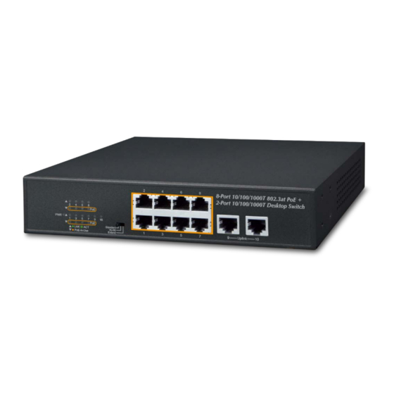
Chapter 2. Hardware Description The switch provides three different running speeds – 10Mbps, 100Mbps and 1000Mbps, and automatically distinguishes the speed of the incoming connection. For easier management and control of the TT-DT10-2G-8GP+, familiarize yourself with its display indicators and ports. Front panel illustrations in this chapter display the unit LED indicators. - Page 9 Extend mode makes the TT-DT10-2G-8GP+ operate as a VLAN isolation switch where 1. Port 1 to port 8 will isolate respectively. 2. Port 1 to port 8 will only communicate with port 9 and port 10 (uplink ports). 3. 30-watt PoE transmit distance of 250m at speed of 10Mbps.
-
Page 10: Rear Panel
2.1.1 LED Indicators System Color Function Green Lights to indicate that the Switch has power. Per 10/100/1000Mbps Port Color Function PoE-in-use Orange Lights to indicate the port is providing 55V DC in-line power. (1-8 ports) Lights to indicate the Switch is successfully connecting to the network at 1000Mbps. Green Blinks to indicate that the Switch is actively sending or receiving data over that port. -
Page 11: Hardware Installation
Chapter 3. Hardware Installation Start up Please refer to the following for your cabling: 10/100/1000BASE-T All 10/100/1000BASE-T ports come with Auto-Negotiation capability. They automatically support 1000BASE-T, 100BASE-TX and 10BASE-T networks. Users only need to plug a working network device into one of the 10/100/1000BASE-T ports, and then turn on TT-DT10-2G-8GP+. -
Page 12: Rack Mounting
Step 1: Attach the rubber feet to the recessed areas on the bottom of the GSD-1008HP, as shown below. Attaching the Rubber Feet to the TT-DT10-2G-8GP+ Step 2: Place the TT-DT10-2G-8GP+ on a desktop near an AC power source. Step 3: Keep enough ventilation space between the TT-DT10-2G-8GP+ and the surrounding objects to allow for air flow. - Page 13 Attaching the Brackets to the TT-DT10-2G-8GP+ You must use the screws supplied with the mounting brackets. Damage caused to the parts by using incorrect screws will invalidate the warranty. Step 3: Secure the brackets tightly. Step 4: Follow the same steps to attach the second bracket to the opposite side. Step 5: After the brackets are attached, use suitable screws to securely attach the brackets to the rack, as shown below Mounting the TT-DT10-2G-8GP+ in a Rack...
-
Page 14: Wall Mounting Installation
3.3 Wall Mounting Installation Step 1: Install two screws on the wall 150mm apart as shown below. Step 2: Hang the TT-DT10-2G-8GP+ on the screws from the wall. Step 3: Repeat step 5 of Desktop Installation for power supply to the Switch Before mounting the device to the wall, please check the location of the elec- trical outlet and the length of the Ethernet cable. -
Page 16: Troubleshooting, Appendix & Customer Support
Chapter 4. Troubleshooting This chapter contains information to help you solve issues. If the TT-DT10-2G-8GP+ is not functioning properly, make sure the TT-DT10-2G-8GP+ was set up according to instructions in this manual. The Link LED is not lit. Solution: Check the cable connection or swap to a different cable. 1000BASE-T port link LED is lit, but the traffic is irregular. - Page 17 Appendix A - Networking Connection A.1 Switch's Data RJ45 Pin Assignments - 1000Mbps, 1000BASE-T 4.1.1.2 MDI-X BI_DA+ BI_DB+ BI_DA- BI_DB- BI_DB+ BI_DA+ BI_DC+ BI_DD+ BI_DC- BI_DD- BI_DB- BI_DA- BI_DD+ BI_DC+ BI_DD- BI_DC- Implicit implementation of the crossover function within a twisted-pair cable, or at a wiring panel, while not expressly forbidden, is beyond the scope of this standard.
- Page 18 he standard cable, RJ45 pin assignment The standard RJ45 receptacle/connector There are 8 wires on a standard UTP/STP cable and each wire is color-coded. The following shows the pin allocation and color of straight-through cable and crossover cable connection: Straight-through Cable SIDE 1 SIDE2 SIDE 1...
- Page 20 Customer Support Thank you for purchasing Transtector products. You can browse our online resources and User’s Manuals on www. Transtector.com. If you require sales or support information, please contact the Transtector support team using the in- formation found below or using Transtector’s online chat tool. Transtector 10701 Airport Road Hayden, Idaho 83835...
Need help?
Do you have a question about the TRANSTECTOR TT-DT10-2G-8GP+ and is the answer not in the manual?
Questions and answers