Table of Contents
Advertisement
Quick Links
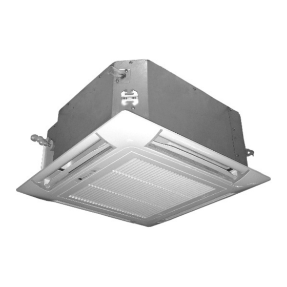
MODELS
4-way blow ceiling mounted cassette
CKV007
CKV009
CKV012
CKV015
CKV018
SAFETY PRECAUTIONS
● Read the following "SAFETY PRECAUTIONS" carefully before installation.
● Carry out test running to confirm that no abnormality occurs after the installation. Then, explain to user the operation, care and maintenance as stated in
instructions. Please remind the customer to keep the operating instructions for future reference.
WARNING
This indication shows the possibility of causing death or serious injury.
CAUTION
This indication shows the possibility of causing harm or damage the equipment.
1) Use qualified installer and follow carefully this instructions. Otherwise it will cause electrical shock, water leakage, or esthetic problem.
2) Install at a strong and firm location which is able to withstand the set's weight. If the strength is not enough or installation is not properly done, the set
will drop and cause injury.
3) For electrical work, follow the local national wiring standard, regulation and this installation instruction. An independent circuit and single outlet must
be used. If electrical circuit capacity is not enough or defect found in electrical work, it will cause electrical shock or fire.
4) Use the specified cable and connect tightly for indoor connection. Connect tightly and clamp the cable so that no external force will be acted on the
terminal. If connection or fixing is not perfect, it will cause heat-up or fire at the connection.
5) Wire routing must be properly arranged so that control board cover is fixed properly. If control board cover is not fixed perfectly, it will cause heat-up
at connection point of terminal, fire or electrical shock.
6) When carrying out piping connection, take care not to let air substances other than the specified refrigerant go into refrigeration cycle. Otherwise, it
will cause lower capacity, abnormal high pressure in the refrigeration cycle, explosion and injury.
7) Do not damage or use unspecified power supply cord. Otherwise, it will cause fire or electrical shock.
8) This equipment must be earthed. It may cause electrical shock if the grounding is not perfect.
9) Do not install the unit at place where leakage of flammable gas may occur. In case gas leaks and accumulates at surrounding of the unit, it may
cause fire.
1) Selection of the installation location.
Select a installation location which is rigid and strong enough to support or hold the unit, and select a location for easy maintenance.
2) Do not release refrigerant.
Do not release refrigerant during piping work for installation, reinstallation and during repairing a refrigeration parts. Take care of the liquid refrigerant.
it may cause frostbite.
3) It may need two people to carry out the installation work.
4) Do not install this appliance in a laundry room or other location where water may drip from the ceiling, etc.
5) Carry out drainage pipes as mentioned in installation instructions. If drainage is not perfect, water may enter the room and damage the furniture.
INSTALLATION MANUAL
WARNING
CAUTION
IM_CKV_1 A 1_GB
Part NO. 468050102/02
Advertisement
Table of Contents

Related Manuals for Airwell CKV007


Summary of Contents for Airwell CKV007
- Page 1 INSTALLATION MANUAL MODELS 4-way blow ceiling mounted cassette CKV007 CKV009 CKV012 CKV015 CKV018 SAFETY PRECAUTIONS ● Read the following "SAFETY PRECAUTIONS" carefully before installation. ● Carry out test running to confirm that no abnormality occurs after the installation. Then, explain to user the operation, care and maintenance as stated in instructions. Please remind the customer to keep the operating instructions for future reference. WARNING This indication shows the possibility of causing death or serious injury. CAUTION This indication shows the possibility of causing harm or damage the equipment. WARNING 1) Use qualified installer and follow carefully this instructions. Otherwise it will cause electrical shock, water leakage, or esthetic problem. 2) Install at a strong and firm location which is able to withstand the set's weight. If the strength is not enough or installation is not properly done, the set will drop and cause injury. 3) For electrical work, follow the local national wiring standard, regulation and this installation instruction. An independent circuit and single outlet must be used. If electrical circuit capacity is not enough or defect found in electrical work, it will cause electrical shock or fire. 4) Use the specified cable and connect tightly for indoor connection. Connect tightly and clamp the cable so that no external force will be acted on the terminal. If connection or fixing is not perfect, it will cause heat-up or fire at the connection. 5) Wire routing must be properly arranged so that control board cover is fixed properly. If control board cover is not fixed perfectly, it will cause heat-up at connection point of terminal, fire or electrical shock. 6) When carrying out piping connection, take care not to let air substances other than the specified refrigerant go into refrigeration cycle. Otherwise, it will cause lower capacity, abnormal high pressure in the refrigeration cycle, explosion and injury. 7) Do not damage or use unspecified power supply cord. Otherwise, it will cause fire or electrical shock. 8) This equipment must be earthed. It may cause electrical shock if the grounding is not perfect. 9) Do not install the unit at place where leakage of flammable gas may occur. In case gas leaks and accumulates at surrounding of the unit, it may cause fire.
-
Page 2: Select The Best Location
Required tools for installation 1.Screw driver 4.Hexagonal wrench 7. Knife 2.Electric drill, hole core drill ( 60 mm) 5.Pipe cutter 8.Measuring tape 3.Spanner 6.Reamer 9.Torque wrench Attached accessories Accessories part Qty. Accessories part Qty. Accessories part Qty. Installation paper board Pipe insulation Clamp Drain hose Washer Sealing material Insulation Bolt Operation manual Installation manual Hoseclamp Bolt Optional accessories Name Used for Note Panel 625mmX625mm Gird ceiling installation Decoration panel is separated from unit when packaging, select proper panel for different installation situation. Panel 725mmX725mm Hard ceiling installation SELECT THE BEST LOCATION... -
Page 3: Unit Installation
Fig 3-1 Unit:mm 1. Use installation template (supplied with the panel) when deciding the suspension bolt position (Fig 4). Fig 5 and table 1 show the dimensions Ceiling opening dimension relationship. 585-680 (Unit: mm) Length Installation Type hook 007/009/012 Ceiling 015/018 Table 1 Ф Liquid Pipe Ф Gas Pipe CKV007 1/4” 1/2” (Ceiling-panel overlapping dimension) CKV009 1/4” 1/2” CKV012 1/4” 1/2” Unit:mm Fig 3-2 CKV015 1/4” 1/2” CKV018 1/4” 1/2” Table 2... -
Page 4: Duct Installation
Suspension bolt Suspension hook Nuts and washers (Use for upper and lower) 2 nuts Supplied bolt Full-scale installation diagram (Supplied with the unit) Fig 6 Fig 7 B Pannel installing (1) Removing the grille a.To open the grille, rotate the grille lock counterclockwise from horizontal position to vertical position.(Fig 8) b.With the grille fully opened, remove the grille along the direction shown in Fig 9. (2) Temporary installation of the panel a. Install two bolts (Accessory) onto the main unit (the corner of refrigerant tubing side and the opposite corner).The detail is shown in Fig 10. Pay attention that leave 15-20mm bolt unscrewed so as to hang the panel easily. b. Attach the panel to the main unit, twist the panel to make sure that the two bolts mentioned above are screwed into the cavity on the panel. Thus the panel can keep balance with the two bolts. Fig 8 c. Pay attention that the TUBE and DRAIN marks on the ceiling panel are in the correct positions on the unit. d. Tighten all bolts (the previously two installed bolts as well as the two remaining bolts.) to secure the panel. e. Pay attention that there should be no gaps between the unit and the ceiling panel, or between the ceiling panel and the ceiling. (3) Wiring of panel a.Connect the 12Pin cable connector from the ceiling panel to the relative connector which comes out of the control box. (Fig 11) If this connector is not connected, the display will not work. Make sure the cable is connected securely. b.Connect the 5Pin cable connector from the ceiling panel to the relative connector comes out of the control box.(Fig 11) If this connector is not connected, the louver will not work. Make sure the cable is connected securely. Fig 9 (4)Attaching the grille Fig 10... -
Page 5: Drain Pipe Connection
DRAIN PIPE CONNECTION A Connect the drain pipe a Use standard hard PVC pipe (19mm) for the drain pipe. b Use the drain hose (Accessory) to change the direction. c Insert the drain hose until it connects the drain port very well, And then secure it tightly with the hose clamp(Accessory). d After checking the drainage, wrap the drain hose with the insulation and clamps (Accessory). Drain clamp (accessory) Insulation (accessory) Drain port Drain hose (accessory) Hard PVC pipe Fig 15 Fig 14 Hard PVC pipe Bracket Connected by hose connector Ceiling 1 1.5m (Prepared on site) NOTE Drain hose(accessory) 1. Make sure the drain pipe has a downward gradient (no less than 1/100) And there are no water traps. 2. Do not raise the drain pipe higher than 1 m, or else there will be water leak risk. 3. To hold the drain pipe, space bracket every 1 to 1.5m.(Fig 16) Fig 16 1/100 gradient or more Clamp(accessory) B Drainage test For VRF system please do drainage test after finishing all installations, wiring and piping included, and doing ITEST (Installation test ) sucessfully: (1) Prepare works please refer to Fig 17. (2) Power on the system, and runs cooling mode. -
Page 6: Electrical Characteristics
Beraker 220~240V AC 50Hz ELB: Electricity leakage breaker. Press the wires under the clips tightly. Size Tightening torque Remote controller and main bus communication wiring and forced off M3.5 0.8~1.0N.m terminal block(4P) Power supply and Ground terminal block(2P) 1.2~1.5N.m Electrical characteristics Unit Power supply Fan motor Model Volts CKV007 0.27 0.06 0.18 CKV009 0.27 0.06 0.18 CKV012 220~240 0.27 0.06 0.18 MCA : Min. Circuit Amps (A) MFA : Max. Fuse Amps(A) CKV015 0.55 0.10 0.32 KW : Fan Motor Rated output(kW) CKV018 0.55...
Need help?
Do you have a question about the CKV007 and is the answer not in the manual?
Questions and answers