Zander Aachen ZX09 Series Operating Manual
Hide thumbs
Also See for ZX09 Series:
- Quick start manual (10 pages) ,
- Operating manual (14 pages) ,
- Quick start manual (10 pages)

Related Manuals for Zander Aachen ZX09 Series


Summary of Contents for Zander Aachen ZX09 Series
- Page 1 ZX09-Series ZX20/ZX21-Series Operating Manual FPGA-based High-Speed Industrial PLC...
- Page 2 Operating manual ZX09/20/21-Series Zander GmbH & Co. KG Am Gut Wolf 15 52070 Aachen, Germany info@zander-aachen.de www.zander-aachen.de Item no.: E61-436-00 Version: M06 This document is the English translation. Technical Changes reserved, all information is subject to change. H. ZANDER GmbH & Co. KG • Am Gut Wolf 15 • 52070 Aachen • Germany • Tel +49 241 9105010 Fax +49 241 91050138 •...
-
Page 3: Table Of Contents
Operating manual ZX09/20/21-Series 1. About this document ................. 6 1.1 Validity ......................6 1.2 Target group ....................6 1.3 Explanation of symbols ................6 2. General safety instructions ................ 7 3. About this device ..................8 3.1 Product information ..................8 3.2 Delivery content and supplies .............. - Page 4 Operating manual ZX09/20/21-Series 5.5.5 The SSI-Interface (only ZX09A, ZX09D and ZX09E) ......27 5.5.6 Connection of an Encoder to the SSI-Interface ........28 5.5.7 TTL differential signal inputs (only ZX09A, ZX09D, ZX09E) ....29 5.5.8 TTL differential signal outputs (only ZX09A, ZX09D, ZX09E) ....29 5.5.9 Connection of the In-/Outputs for the TTL differential signals ....
- Page 5 Operating manual ZX09/20/21-Series 10. Maintenance, repair and replacement ............ 51 11. Dimensional drawing ................52 12. Technical data ................... 53 12.1 ZX09 / ZX09A .................... 53 12.2 ZX09B / ZX09C / ZX09D / ZX09E............. 55 12.3 ZX20T/TP/TC, ZX21T/TP/TC ..............57 12.4 FPGA logic capacities ................
-
Page 6: About This Document
Operating manual ZX09/20/21-Series About this Document Validity This document ist valid for the programmable logic controllers ZX09 (Item-no.: 589200), ZX09A (Item-no.: 589201), ZX09B (Item-no.: 589202), ZX09C (Item-no.: 589203), ZX09D (Item-no.: 589204), ZX09E (Item-no.: 589205), ZX20T (Item-no.: 589000), ZX20TP (Item-no.: 589002), ZX20TC (Item-no.: 589003), ZX21T (Item-no.: 589051), ZX21TP (Item-no.: 589052), ZX21TC (Item-no.: 589053). -
Page 7: General Safety Instructions
Operating manual ZX09/20/21-Series General safety instructions Only authorised and qualified personnel may install the device and put it into operation, i.e. personnel which - is well-acquainted with correct technical handling of the electrical machine equipment, - is familiar with the applicable regulations concerning occu- pational safety and accident prevention, - has read and understood the operating manual and, if applicable, the programming manual... -
Page 8: About This Device
Operating manual ZX09/20/21-Series About this device Product information The ZX09– and ZX20/21-series are high-speed industrial programmable logic control- lers (PLCs). They can be used as stand-alone PLCs or in a network as decentralized PLCs for parallel processing of signals in real time. This is made possible by the heart of every ZX-control: A Field Programmable Gate Array (FPGA). -
Page 9: Delivery Content And Supplies
Operating manual ZX09/20/21-Series Delivery content and supplies Delivery content High-Speed-PLC ZX09 (Item.-no.: 589200), ZX09A (Item-no.: 589201), ZX09B (Item-no.: 589202), ZX09C (Item.-no.: 589203), ZX09D (Item.-no.: 589204), ZX09E (Item.-no.: 589205) or ZX20T (Item.-no.: 589000), ZX20TP (Item.-no.: 589002), ZX20TC (Item.-no.: 589003), ZX21T (Item.-no.: 589051), ZX21TP (Item.-no.: 589052) or ZX21TC (Item.-no.: 589053) ... -
Page 10: Intended Usage
Operating manual ZX09/20/21-Series Intended usage The ZX09- und ZX20/21-Series have been designed for the use in machines and plants for industrial use. They must be installed in switch cabinets or appropriate hous- ings with minimum degree of protection IP54. The approved operating parameters for use must be complied with (see chapter 12 “Technical data”). -
Page 11: Device Diagram
Operating manual ZX09/20/21-Series Device diagram 3.6.1 ZX09 Power Supply Digital Outputs Power FPGA Controller ZX09 06 07 Digital Inputs Fig. 1: Device diagram ZX09 3.6.2 ZX09A Power Supply Digital Outputs Power FPGA Controller Analog to Digital Converter ZX09A 06 07 2- CK+ DT+ DT- Analog... -
Page 12: Zx09B / Zx09C / Zx09D / Zx09E
Operating manual ZX09/20/21-Series 3.6.3 ZX09B / ZX09C / ZX09D / ZX09E Power Supply Digital Outputs RS-485 RS-485/SSI: Power FPGA Controller Only ZX09D/E ZX09B/C/D/E Conv. Conv. Conv. Conv. Conv. Conv. CK+ CK- DT+ A1+ 0V A2+ 0V A3+ 0V A4+ 0V Switchable Digital Non - switchable... -
Page 13: Zx20T/Tp/Tc, Zx21T/Tp/Tc
Operating manual ZX09/20/21-Series 3.6.5 ZX20TP / ZX20TC / ZX21TP / ZX21TC ZX20TP ZX20TC ZX21TP ZX21TC Fig. 5: Device diagram ZX20TP / ZX20TC / ZX21TP / ZX21TC Assembly Please note: The device must be installed in a switch cabinet or suitable housing with a minimum degree of protection of IP54 ... -
Page 14: Disassembly Off The Mounting Rail
Operating manual ZX09/20/21-Series Fig. 6: Place device on top hat rail Fig. 7: Press device onto top-hat rail Disassembly off the mounting rail The two orange locking slides (top and bottom) are pulled out one after the other with a screwdriver (blade width max. 3.5 mm) (see Fig. 8). The device is then released from the top-hat rail and can be removed. -
Page 15: Electrical Connection
It is recommended to use shielded network cables of category Cat. 7 for the network connection. For connection to the SSI or RS 485 interface (ZX09 series only) a shielded, twisted pair cable is required (see Fig. 15). -
Page 16: Connection Terminals
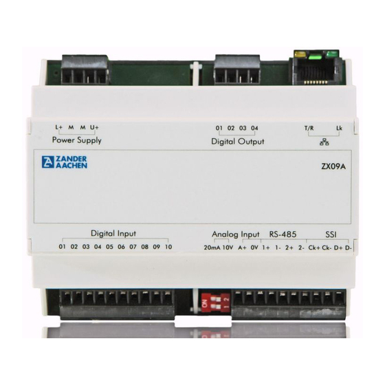
Operating manual ZX09/20/21-Series Connection terminals 5.2.1 ZX09 / ZX09A / ZX09B / ZX09C / ZX09D / ZX09E Terminal Description Positive supply voltage U M (2 equivalent terminals) Connection 0 V of the supply voltage and the voltage for the digital outputs and 0 V potential for digital and analog inputs. - Page 17 Operating manual ZX09/20/21-Series 1 2 3 01 02 03 04 L+ M M U+ Power Supply Digital Output ZX09A Digital Input Analog Input RS-485 01 02 03 04 05 06 07 08 09 10 20mA 10V A+ 0 V 1+ 1- 2+ 2- Ck+ Ck- D+ D- Fig.
-
Page 18: Zx20T/Tp/Tc, Zx21T/Tp/Tc
Operating manual ZX09/20/21-Series 5.2.2 ZX20T/TP/TC, ZX21T/TP/TC Terminal Description Positive supply voltage U M (2 equivalent terminals) 0 V - Connection of the supply voltage and the voltage for the digital outputs and 0 V potential for digital inputs. M and 0 V are internally connected Positive voltage for the dig. -
Page 19: Failure Safety
Operating manual ZX09/20/21-Series Failure safety The operating voltage L+ / M is reverse polarity protected. All digital outputs are short-circuit proof. Warning: The switching capacity and the switching capacity of the power supply unit specified in chapter 12 "Technical data" must be observed. information for the digital outputs must be observed. -
Page 20: Inputs
"03", ... , "20" are continuously assigned to the digital inputs "01", "02", "03", ... , "20". The ZX09 series do not have LEDs to indicate the input states. H. ZANDER GmbH & Co. KG • Am Gut Wolf 15 • 52070 Aachen • Germany • Tel +49 241 9105010... -
Page 21: Digital Inputs
Operating manual ZX09/20/21-Series 5.5.1 Digital Inputs ZX09 ZX09A controllers provide digital inputs ZX09B/C/D/E controllers two. These are accessible via the connection terminals "Digital Input 01..10" or "Digital Input 01..02". The ZX20T, ZX20TP and ZX20TC and ZX21T, ZX21TP and ZX21TC have 20 digital inputs. -
Page 22: Connection Of The Digital Inputs
5.5.2 Connection of the digital Inputs The connection of the digital inputs for the ZX09 series is shown in Figs. 15A and 15B using the ZX09 / ZX09A controller as an example. The connection of the digital inputs of the ZX09B/C/D/E controllers is identical, the only difference is the number of inputs. - Page 23 Operating manual ZX09/20/21-Series 24 V L+ M M Power Digital Output Digital Input Digital Input 01 02 03 04 05 06 07 08 09 10 11 12 13 14 15 16 17 18 19 20 18-30V Fig. 14 A: Connection of the digital inputs (unshielded) - ZX20/21-series 24 V L+ M M Power...
- Page 24 Operating manual ZX09/20/21-Series 24 V Power Supply Digital Input 09 10 18-30V Fig. 15 A: Connection of the digital inputs (unshielded) - ZX09-series 24 V Power Supply Digital Input 09 10 Shield rail 18-30V (PE) Fig. 15 B: Connection of the digital inputs (shielded) - ZX09-series H.
-
Page 25: Analog Inputs (Only Zx09A/B/C/D/E)
Operating manual ZX09/20/21-Series 5.5.3 Analog inputs (only ZX09A, ZX09B, ZX09C, ZX09D, ZX09E) The following device variants provide a different number of analog inputs: Device version Number (total) Description ZX09A 1 switchable input: 0..10 V or 4..20 mA ZX09B and 4 fixed inputs: 0..10 V ZX09D 2 switchable inputs: 0..10 V or 4..20 mA ZX09C and... -
Page 26: Connection Of The Analog Inputs
Operating manual ZX09/20/21-Series 5.5.4 Connection of the analog inputs Fig. 16 shows an example of how to connect the analog input to a ZX09A controller for a voltage measurement. The signal generated by the sensor is connected to terminals A+ and 0V via a shielded cable. The supply line of the analog input must be made with a shielded cable. -
Page 27: The Ssi-Interface (Only Zx09A, Zx09D And Zx09E)
Operating manual ZX09/20/21-Series 5.5.5 The SSI-Interface (only ZX09A, ZX09D and ZX09E) The ZX09A controller has up to two SSI interfaces. These are identified on the unit by the SSI and RS-485 terminals. An absolute encoder can be connected via this interface. -
Page 28: Connection Of An Encoder To The Ssi-Interface
Operating manual ZX09/20/21-Series 5.5.6 Connection of an Encoder to the SSI-Interface Fig. 18 shows the connection of an encoder to the SSI interface. The cables of the SSI encoder are connected to the control system via a shielded cable twisted in pairs. Connect the cable shield at one end as close as possible to the terminals of the control with a low-resistance shielding rail at PE potential (see Fig. -
Page 29: Ttl Differential Signal Inputs (Only Zx09A, Zx09D, Zx09E)
Operating manual ZX09/20/21-Series 5.5.7 TTL differential signal inputs (only ZX09A, ZX09D, ZX09E) The SSI or RS-485 interfaces can also be used to connect sensors with TTL differ- ential outputs, e.g. corresponding incremental encoders with rectangular TTL out- puts. Up to four TTL differential inputs are available via the "SSI" and "RS485" inter- faces (see also section 5.5.9, Connecting the inputs/outputs for TTL differential signals). -
Page 30: Digital Outputs
The ZX09 series controllers have 4 digital outputs and the ZX20/21 series controllers have 16 digital outputs. These are accessible on the ZX20/21 series via the two upper terminal blocks (see Fig. 20) and on the ZX09 series via the upper right terminal block (see Fig. 19). -
Page 31: Connection Of The Digital Outputs
5.6.1 Connection of the digital outputs The connection of the digital outputs of the ZX09 series is shown in fig. 19, the con- nection of the ZX20/21 series in fig. 20. Different actuators (e.g. relays) can be con- nected to the terminals of the outputs. Their 0 V potential is connected to the 0 V potential of the voltage source for the digital outputs (terminal "M"). - Page 32 Operating manual ZX09/20/21-Series 10-30 V 24 V 1 2 3 4 Power Supply Digital Output Fig. 19. Connection of the digital outputs (here e.g. relays) - ZX09-series 10-30 V 24 V 09 10 Digital Output Fig. 20. Connection of the outputs (here e.g. relays) - ZX20/21-series H.
-
Page 33: Programming
Operating manual ZX09/20/21-Series Programming For programming, the separately available programming system "EX_PRESS 5" is required. The program is created in the PLC programming language "Structured Text" according to IEC 61131-3. The finished program is downloaded to the controller via the Ethernet interface, which is marked on the device by the "... -
Page 34: Networking
Operating manual ZX09/20/21-Series Important information: In the case of the ZX20TC, ZX20TP, ZX21TC and ZX21TP controllers, downloading of the completed program into the controller is only possible if data are not simultaneously transferred via the PROFINET or EtherCAT interface. With all other networking types, downloading is also possible while com- munication is running;... - Page 35 Operating manual ZX09/20/21-Series Note: Detailed information about configuration and programming of the Modbus/ TCP communication can be found in the programming manual in chapter 9.2, which can be found as a PDF file in the software package "EX_PRESS 5" (Version 4.20 or higher, Art-no. 589092) on the USB stick enclosed there.
-
Page 36: Zandernet
Operating manual ZX09/20/21-Series 7.1.2 ZanderNet The ZanderNet network protocol offers a further option for networking the controllers with each other via the Ethernet interface. Here, only Zander controllers of the ZX series communicate with each other (even different types from the ZX09 and ZX20/ ZX21 series mixed together) and form a distributed control system together. - Page 37 Operating manual ZX09/20/21-Series ETHERNET– SWITCH Fig. 23. Networking via ZanderNet (e.g. with ZX09A) H. ZANDER GmbH & Co. KG • Am Gut Wolf 15 • 52070 Aachen • Germany • Tel +49 241 9105010 Fax +49 241 91050138 • info@zander-aachen.de • www.zander-aachen.de...
-
Page 38: The Rs 485-Interface (Only Zx09A, Zx09D And Zx09E)
Operating manual ZX09/20/21-Series The RS 485-Interface (only ZX09A, ZX09D and ZX09E) The controllers ZX09A, ZX09D and ZX09E have a RS-485/RS-422 interface. This is indicated on the device by the "RS-485" terminal. The interface marked "SSI" can also be used as a second RS-485/RS-422 interface as an alternative for communication with an SSI compatible device (e.g. -
Page 39: Modbus Rtu Wiring
Operating manual ZX09/20/21-Series 7.2.2 Modbus RTU wiring The connection of one or more Zander controllers to a Modbus RTU Master is made via the connections 2+ and 2- of the RS-485 interface using a shielded twisted-pair two-wire cable (see Fig. 24). The shield must be connected to a shielding rail at one end with low impedance as close as possible to the device. -
Page 40: Zanderlink
Operating manual ZX09/20/21-Series Example for Modbus RTU master: Zander HMI-series „MVisio“, 1 2 3 1 2 3 https://www.zander-aachen.de/de/ ZX09A ZX09A automation/hmi/mvisio-serie.html 120 Ohm RS-485 RS-485 120 Ohm Fig. 25: Bus topology Modbus RTU (e.g. on ZX09A) 7.2.3 ZanderLink Another way of using the RS-485 interface (or alternatively the SSI interface) is the point-to-point connection of two ZX controllers using "ZanderLink". -
Page 41: Zanderlink Wiring
Operating manual ZX09/20/21-Series 7.2.4 ZanderLink wiring ZanderLink uses the complete RS-485 interface for the connection per subscriber, i.e. all four terminals, since it is a synchronous serial transmission (one channel for a clock signal, the second channel for the data bits). The connection of two Zander controllers via ZanderLink is made via the terminals 1+ and 1- as well as 2+ and 2- of the RS-485 interface using a shielded twisted-pair four-wire cable (see Fig. -
Page 42: Networking Via Profinet (Only Zx20Tp, Zx21Tp)
Operating manual ZX09/20/21-Series Networking via Profinet (only ZX20TP, ZX21TP) The ZX20TP or ZX21TP controller can be integrated into a PROFINET network as a "PROFINET IO Device". There it serves as subsystem and exchanges data with a "PROFINET IO Controller". One of the two RJ45 sockets of the "PROFINET IO Device" interface is connected to the "PROFINET IO Controller"... -
Page 43: Networking Via Ethercat (Only Zx20Tc, Zx21Tc)
Operating manual ZX09/20/21-Series Networking via EtherCAT (only ZX20TC, ZX21TC) The ZX20TC or ZX21TC controller can be integrated into an EtherCAT network as an "EtherCAT slave". There it serves as a subsystem and exchanges data with an "EtherCAT Master". The right RJ45 socket ("IN") is connected to the "EtherCAT Master" or the "OUT" of a previous "EtherCAT Slave". -
Page 44: Commissioning
The controllers of the ZX09 series, as well as the ZX20/21 series are not suitable for fulfilling functional safety tasks. Therefore, if dangerous movements or dangerous states are possible in the overall system, a risk assessment must be carried out in accordance with the Machinery Directive. -
Page 45: Initial Commissioning
When programming is complete, the inputs can be connected. Proceed as described in section 5.5.2 "Connecting the digital inputs" and section 5.5.4 "Connecting the analog inputs" (ZX09 series only). If no input signals are provided, this step can be skipped. -
Page 46: Step 5: Connecting The Encoder (Zx09A, Zx09D, Zx09E)
Operating manual ZX09/20/21-Series 8.2.5 Step 5: Connecting the encoder (ZX09A, ZX09D, ZX09E) Now connect the encoder as described in section 5.5.6 "Connecting a device to the SSI interface". If the connection of an encoder is not intended, this step can be skipped. 8.2.6 Step 6: Controlling the function of the PLC via the LEDs Before connecting the network and the outputs, the operation of the PLC should be... -
Page 47: Step 8: Connecting The Outputs
The green "RUN" LED on the ZX09 series outputs flashing codes in the event of an error. For this purpose, the start code "2 s light, 2 s dark, 2 s light" is cyclically output,... - Page 48 Operating manual ZX09/20/21-Series 1 2 3 4 01 02 03 04 L+ M M Digital Output Power Supply ZX09A RUN-LED OC-LED Output-LEDs Fig. 28: Diagnosis LEDs (ZX09A, exemplary) L+ M M 01 02 03 04 05 06 07 08 09 10 11 12 13 14 15 16 Power Digital Output Link...
- Page 49 Operating manual ZX09/20/21-Series The following tables list the possible states of the LEDs and their meaning for the control variants with PROFINET interface (ZX20TP, ZX21TP) or EtherCAT interface (ZX20TC, ZX21TC). ZX20TP, ZX21TP: Color Status Meaning Green Bus module ready for operation Green/ Flashing Yellow...
- Page 50 Operating manual ZX09/20/21-Series ZX20TC, ZX21TC: Color Status Meaning Green Bus module ready for operation Green/ Flashing Yellow Green/Yellow Bus module moves up Yellow Device is switched off or bus module is defective Flashing Invalid configuration Single flash Local error: The slave device application has changed the EtherCAT state independently Double flash Process data watchdog timeout...
- Page 51 Operating manual ZX09/20/21-Series Dimensional drawing 90 mm Fig. 30: Dimensional drawing (exemplary: ZX09A) H. ZANDER GmbH & Co. KG • Am Gut Wolf 15 • 52070 Aachen • Germany • Tel +49 241 9105010 Fax +49 241 91050138 • info@zander-aachen.de • www.zander-aachen.de...
-
Page 52: Maintenance, Repair And Replacement
Operating manual ZX09/20/21-Series Maintenance, repair and replacement Assuming correct installation, maintenance work is not required. Repairs to the device may only be carried out by the manufacturer. Opening the device by the user will result in the loss of any warranty or guarantee claims. For a possibly necessary replacement, it must be ensured that the new control unit is provided with the identical user program before it is put into operation again. -
Page 53: Technical Data
Operating manual ZX09/20/21-Series Technical data 12.1 ZX09 / ZX09A Electrical data Operating voltage U (terminals „L+“ and „M“) DC 24 V Voltage tolerance ± 15% Inrush current (with power-on) for <500 ms approx. 200 mA Current consumption at 24 V approx. - Page 54 Operating manual ZX09/20/21-Series Analog Input (ZX09A) Quantity Type 0..10 V or 0..20 mA Resolution 12 Bit Accuracy Range 1 (0-10 mA): ±0.1% of full scale (20mA) Range 2 (10-20 mA): ±0.2% of full scale (20mA) Range 3 (0-10V): ±0.1% of full scale (10V) Offset ≤...
-
Page 55: Zx09B / Zx09C / Zx09D / Zx09E
Operating manual ZX09/20/21-Series 12.2 ZX09B / ZX09C / ZX09D / ZX09E Electrical data Operating voltage U (terminals „L+“ and „M“) DC 24 V Voltage tolerance ± 15% Inrush current (with power-on) for <500 ms approx. 200 mA Current consumption at 24 V approx. - Page 56 Operating manual ZX09/20/21-Series Resolution 12 Bit Accuracy Range 1 (0-10 mA): ±0.1% of Final measurement value (20mA) Range 2 (10-20 mA): ±0.2% of Final measurement value (20mA) Range 3 (0-10V): ±0.1% of Measurement end value (10V) Offset ≤ ±2 mV or. ≤ ±0,0004 mA Linearity Current measurement: ≤...
-
Page 57: Zx20T/Tp/Tc, Zx21T/Tp/Tc
Operating manual ZX09/20/21-Series 12.3 ZX20T/TP/TC, ZX21T/TP/TC Electrical Data Operating voltage U (Terminal „L+“ und „M“) DC 24 V (± 15%) Current input at U for ZX20T, ZX21T approx. 60 mA for ZX20TP/TC, ZX21TP/TC approx. 160 mA (all inputs activated / without load) Power consumption at U for ZX20T, ZX21T approx. -
Page 58: Fpga Logic Capacities
Operating manual ZX09/20/21-Series Environmental data Ambient temperature 0 °C to 50 °C Storage temperature -20 °C to 80 °C Moisture stress 93% r.m. at +40 °C, dewless Vibrations according to EN 61131-2 Frequency: 5 - 8.4 Hz, 3.5 mm amplitude Frequency: 8.4 - 150 Hz, 1.0 g acc. -
Page 59: Example 1
Operating manual ZX09/20/21-Series Example 1 In this example, the steps of initial commissioning (see section 8.2) are carried out with a ZX09A for a specific example. Starting with the development of a program in step 1, the individual steps are carried out until the system is fully operational after completion of step 9. -
Page 60: Step 1: Program Creation In Ex_Press 5
Operating manual ZX09/20/21-Series Push button switch Proximity switch Pressure sensor Belt 3 Belt 2 Belt 1 Light barrier 2 Light barrier 1 Fig. 31: Principle Diagram of the filling plant 13.2 Program creation in EX_PRESS 5 In the following the program corresponding to the application is shown. In the first part of the program, marked by "DECLARATION", all necessary variables are declared and partly also initialized. - Page 61 Operating manual ZX09/20/21-Series filling process (hopper), the control of the conveyor belts 1 and 2 (belt 1 / belt 2) and the error signal. Under "VAR_ADC" the analog input "pressure sensor" is declared. This is the pres- sure sensor, which should continuously record the filling status. Under "VAR"...
- Page 62 Operating manual ZX09/20/21-Series END_VAR; (*The input signals of the light barrier are debounced here. Therefore the container can be detected by the sensor. The 1000ms correspond to the time the container needs to be transported past the sensor.*) Lightbarrier1.TDB :=1000ms; Lightbarrier2.TDB :=1000ms;...
- Page 63 Operating manual ZX09/20/21-Series (*If the proximity switch is activated while belt 2 is running and the push button is not operated, belt 2 is stopped.*) ELSIF Proxswitch=1 AND Belt2=1 AND Psuhbuttonswitch=0 THEN Belt2 :=0; (*If there is a proximity switch at the filling position, the filling process is carried out. This maintains itself until the container has been filled.
-
Page 64: Step 2: Connecting The Power Supply
Operating manual ZX09/20/21-Series Mistake :=0; END_IF; (*****************************************************************************************************************) (*--------------------TIMERS--------------------*) timer1.POL :=HIGH; timer1.MODE :=CONT; timer1.ENABLE :=1; timer1.RESET :=0; Timer1 :=50 us; Funnel.CLK :=timer1; Belt1.CLK :=timer1; Belt2.CLK :=timer1; filled.CLK :=timer1; Mistake.CLK :=timer1; Error.CLK :=timer1; initial.CLK :=timer1; END_PROGRAM; 13.3 Step 2: Connecting the power supply As described in Chapter 5.4 "Electrical connection of the device", the power supply is connected to the controller. -
Page 65: Step 6: Controlling The Function Of The Plc Via The Leds
Operating manual ZX09/20/21-Series In this example the pressure sensor supplies a voltage signal of 0 V - 10 V. For this reason, both switches next to the analog terminals on the controller are set to 10 V (see Chapter 5.5.3 "Analog Inputs (only ZX09A/B/C/D/E)"). Step 5 is omitted, since the application does not provide an encoder. -
Page 66: Step 9: Connecting The Power Supply Of The Digital Outputs
Operating manual ZX09/20/21-Series 13.7 Step 8: Connecting the outputs Fig. 33 shows the connection of the digital outputs. As with the connection of the in- puts, make sure that the cabling is connected to the correct terminals. The control of the filling process must therefore be connected to terminal 1, the control of volume 1 to terminal 2, the control of volume 2 to terminal 3 and the error status display to terminal 4. -
Page 67: Example 2
Operating manual ZX09/20/21-Series Example 2 In this example, the steps of initial commissioning (see section 8.2) are carried out for a specific example. Starting with the development of a program in step 1, the individual steps are carried out until the system is fully operational after completing step 9. 14.1 The process In this example the control of a good/bad part sorting shall be shown. -
Page 68: Step 1: Program Creation In Ex_Press 5
Operating manual ZX09/20/21-Series Pos. 4 Pos. 1 Pos. 2 Pos. 3 Pos. 5 Colour sensor Height control Light barrier Light barrier Fig. 34. Principle Diagram of good/bad part sorting 14.2 Step 1: Program creation in EX_PRESS 5 In the following the program for application is shown. In the first part of the program, marked by "DECLARATION", all necessary variables are declared. - Page 69 Operating manual ZX09/20/21-Series For this purpose the signals of the light barriers are first debounced with 200 ms. This ensures that only passing components activate the light barrier. The status bit of the respective sorting is now set via an IF query. If the component is too high and passes the light barrier, Fail1 is set to 1, otherwise Fail1 is set to 0.
- Page 70 Operating manual ZX09/20/21-Series timerDoor1; timerDoor2; END_VAR; (*************************LOGIC-PART*******************) (*Debouncing of the input signals of the light barriers*) Light1.TDB:=200ms; Light2.TDB:=200ms; (*If 1. the light barrier 2 is activated and 2. the component is detected as too high, Fail1 is set*) IF Light1=1 AND timerHigh=1 THEN Fail1:=1;...
-
Page 71: Step 2: Connecting The Power Supply
Operating manual ZX09/20/21-Series timerHigh.RESET:=High; timerHigh.POL:=HIGH; timerHigh.MODE:=SINGLE_SHOT_SE; timerHigh:=1s; (*If the component is recognized as too wrongly colored, "timerColor" is started and keeps the value until the light barrier 2* is reached) timerColor.ENABLE:=1; timerColor.RESET:= Color; timerColor.POL:=HIGH; timerColor.MODE:=SINGLE_SHOT_SE; timerColor:=1s; END_PROGRAM; 14.3 Step 2: Connecting the power supply As described in section 5.4 "Electrical connection of the device", the power supply is connected to the controller. -
Page 72: Step 6: Controlling The Function Of The Plc Via The Leds
Operating manual ZX09/20/21-Series L M M 01 02 03 04 05 06 07 08 09 10 11 12 13 14 15 16 Power Digital Output Digital Output Digital Input Digital Input 11 12 13 14 15 16 17 18 19 20 01 02 03 04 05 06 07 08 09 10 Height sensor Light barrier 2... -
Page 73: Step 9: Connecting The Power Supply Of The Digital Outputs
Operating manual ZX09/20/21-Series Trapdoor 1 Trapdoor 2 01 02 03 04 05 06 L M M 07 08 09 10 11 12 13 14 15 16 Power Digital Output Digital Output Digital Input Digital Input 01 02 03 04 05 06 07 08 09 10 11 12 13 14 15 16 17 18 19 20 Fig. -
Page 74: Declaration Of Conformity
Operating manual ZX09/20/21-Series Declaration of conformity H. ZANDER GmbH & Co. KG • Am Gut Wolf 15 • 52070 Aachen • Germany • Tel +49 241 9105010 Fax +49 241 91050138 • info@zander-aachen.de • www.zander-aachen.de... -
Page 75: Service
Operating manual ZX09/20/21-Series Service Contact us in case of service: H. Zander GmbH & Co. KG Am Gut Wolf 15 52070 Aachen Germany Service phone: Within Germany: (0241) 910501-0 From abroad: +49 241 910501-0 E-Mail: info@zander-aachen.de Internet: www.zander-aachen.de H. ZANDER GmbH & Co. KG • Am Gut Wolf 15 • 52070 Aachen • Germany • Tel +49 241 9105010 Fax +49 241 91050138 •...
Need help?
Do you have a question about the ZX09 Series and is the answer not in the manual?
Questions and answers