Table of Contents
Advertisement
Quick Links
Advertisement
Table of Contents

Related Manuals for Zander Aachen SCB Series


Summary of Contents for Zander Aachen SCB Series
- Page 1 Operating Instruction Safety Time Control Device SCB...
- Page 2 Safety Time Control Device SCB H. Zander GmbH & Co. KG Am Gut Wolf 15 52070 Aachen, Germany info@zander-aachen.de www.zander-aachen.de Number: E61-049-00 Version: M01 Engl. Translation of the original document Subject to technical modifications, no responsibility is accepted for the accuracy of this information. H.
-
Page 3: Table Of Contents
Safety Time Control Device Contents 1. Scope 2. Target group 3. Safety instructions 4. Appropriate use 5. Disclaimer and warranty 6. Features 7. Functions 7.1 Functions of the safety circuit I21-I11 and I22-I12 7.2 Functions of the reset circuit X1 7.3 Functions of the feedback loop Y1 7.4 Functions of the safe semiconductor output P1 and O2 7.5 Functions of the safe relay contact 17-18 and 27-28... - Page 4 Safety Time Control Device SCB 13. Configuration of the SCB 13.1 Loading a configuration 13.2 Parametrization of a delay time 14. Commissioning procedure 15. Diagnostic functions 15.1 Operating state wir Off-delay outputs/contacts 15.2 Operating state wir On-delay outputs/contacts 15.3 Configuration display 15.4 Error monitoring 16.
-
Page 5: Scope
Safety Time Control Device 1. Scope This document is valid for: Order-No. Order-No. Type Plug-in screw terminals Plug-in spring-cage terminals SCB-04 474460 475460 SCB-03 474480 475480 SCB-02 474490 475490 SCB-04m 474461 475461 SCB-03m 474481 475481 SCB-02m 474491 475491 SCB-04h 474462 475462 SCB-03h 474482... -
Page 6: Appropriate Use
Safety Time Control Device SCB • Installation, commissioning, maintenance, and decommissioning should be done only by authorised and qualified technicians: − who are familiar with proper handling of the safety components − who are familiar with the applicable EMC and ESD regulations −... -
Page 7: Disclaimer And Warranty
Safety Time Control Device Appropriate use also includes compliance with: EN ISO 13849-1, Safety-related parts of controllers, EN 60204-1, Electrical equipment in machines. For further information please refer to the above mentioned documents. ATTENTION! The user is responsible for integrating the device into a safe overall system. For this pur- pose, the overall system has to be validated, e.g. -
Page 8: Features
Safety Time Control Device SCB This means that the connected load is switched off as soon as a request from connected sensor elements or diagnostic measures detects a dangerous state, e.g. caused by a component fault. Since process-related applications in particular have high demands on availability, limited availability can also have significant consequences. -
Page 9: Functions
Safety Time Control Device 7. Functions The safety time control device SCB is conceptualised for the safe isolation of safety circu- its according to EN 60204-1 and can be used in safety applications up to, PL e, Cat. 4, SIL 3 as well as on furnaces in continuous operation according to EN 50156-1 and EN 746-2. -
Page 10: Functions Of The Safe Semiconductor Output P1 And O2
Safety Time Control Device SCB 7.4 Functions of the safe semiconductor outputs O1 and O2 Taking into account the selected configuration, the safe PNP semiconductor outputs switch on when the safety circuit is closed. Opening the safety circuit leads to a switch-off. 7.5 Functions of the safe relay contacts 17-28 and 27-28 Taking into account the selected configuration, the safe relay contacts switch on when the safety circuit is closed. -
Page 11: Application Example
Safety Time Control Device ATTENTION If the function switch-off delay with automatic re-trigger function is used, the automatic reset at the moment of re-triggering has to be considered separately, since the monito- red, manual start is disabled in this moment. 8. - Page 12 Safety Time Control Device SCB With the selected configuration Pr06, which allows a monitored, manual start with automa- tic re-trigger function as well as a time-delayed switch-off of the safe relay contacts, the SCB-02 filters a short-time triggering of the connected pressure-switch up to 10 seconds. If an overpressure is detected, the time delay at the SCB-02 is triggered.
- Page 13 Safety Time Control Device Figure 3: Application example - Time delay reset with two reset buttons Figure 4: Wiring example füfor application example - Time delayed reset H. ZANDER GmbH & Co. KG • Am Gut Wolf 15 • 52070 Aachen • Deutschland • Tel +49 241 9105010 Fax +49 241 91050138 •...
-
Page 14: Mounting
Safety Time Control Device SCB 9. Mounting The device has to be installed in a cabinet having minimum protection class of IP54: • Mount on a 35 mm mounting rail as per EN 60715 • For optimum heat dissipation, mount with ventilation slots facing upwards •... -
Page 15: Electrical Connection
Safety Time Control Device 10. Electrical connection • Wiring only be carried out while the voltage supply is switched off • Do not connect any external voltages to the outputs O1, O2, C1 and C2 • The outputs O1, O“, C1 and C2 are short-circuit-proofed. Overloading is not allowed and results in damage to the device (see „Technical data“) •... -
Page 16: Checks, Maintenance And Proof-Test
Safety Time Control Device SCB 11. Checks, maintenance and Proof-Test 11.1 Checks and maintenance The following checks are regularly required to ensure proper and continuous functioning: • Check the switching function • Check for signs of manipulation and safety function bypassing •... -
Page 17: Wiring
Safety Time Control Device 12. Wiring Depending on application or result of the risk assessment, e.g. according to EN ISO 13849-1, the device should be wired according to Figure 7 to 17. 12.1 Wiring reset circuit Figure 7: Figure 8: Automatic reset Monitored manual reset. -
Page 18: Wiring Supply Voltage
Safety Time Control Device SCB Figure14: Dual-channel emer- gency stop circuit with PNP semiconductor outputs / OSSD out- puts with seüerate cross circuit detection. For safety applications up to PL e, Cat. 4, SIL 3. 12.4 Wiring supply voltage Figure 15: Connection of the power supply to the terminals A1 and 12.5 Wiring safe relay contacts and safe semiconductor outputs... -
Page 19: Configuration Of The Scb
Safety Time Control Device 13. Configuration of the SCB The SCB is delivered with the default configuration "Pr00". With this configuration, the device evaluates the safety circuit and the reset circuit according to the configuration table. However, no delay time is executed. A parameterization of the delay time is therefo- re not possible. - Page 20 Safety Time Control Device SCB After the menu item "Pu" has been displayed for approx. 2 seconds, the PUK can be ente- red (see Figure 19). Enter Enter Enter (2s) Figure 19: PUK procedure 1. bis 3. PUK enty: first digit of the PUK is set by turning the push/rotary button. The first PUK digit is saved by pressing the button briefly and the second PUK digit can be set in the same way as the first one.
-
Page 21: Parametrization Of A Delay Time
Safety Time Control Device ATTENTION! • Make sure that the supply voltage of the device is safely applied during loading the new configuration. A power-off during the loading process leads to a non-acknowledgeable error condition. In this case, the device must be returned to the manufacturer •... - Page 22 Safety Time Control Device SCB 2. to 5. PIN entry The access to PIN Entry is signalled by the indication „Pn“. The first digit of the PIN is shown as blinking. The first digit of the PIN is set by turning the push/rotary button. The first PIN digit is saved by pressing the button briefly and the second PIN digit can be set in the same way as the first one.
-
Page 23: Commissioning Procedure
Safety Time Control Device 14. Commissioning procedure 1. Wiring the supply voltage Connect the supply voltage to the device according to chapter 12.4. 2. Set desired device configuration and delay time Supply the device with power and set the desired device configuration and delay time (see chapter 13). -
Page 24: Diagnostic Functions
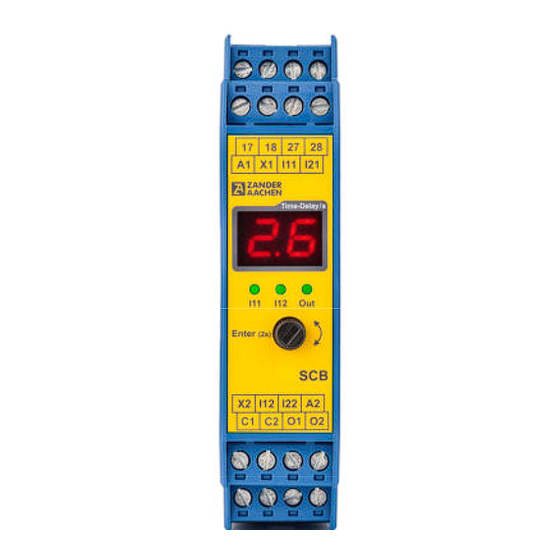
Safety Time Control Device SCB 15. Diagnostic functions The SCB has several diagnostic options. In addition to a two-digit display, which shows the currently parameterized delay time and configuration as well as error messages, three status LEDs are available for the IO status display. Table 3 explains the symbols of the status LEDs used in the following. -
Page 25: Operating State Wir On-Delay Outputs/Contacts
Safety Time Control Device 2. to 4. Operating state In the operating state, the display shows the delay time currently stored in the SCB. The three LEDs I11, I12 and Out provide information about the current status of the inputs and outputs. -
Page 26: Configuration Display
Safety Time Control Device SCB 3. to 4. Closing of the safety circuit Through the closing of the safety circuit in combination with a start, the non-delayed out- puts/contacts are immediately switched on. The blinking Out LED as well as the count- down shown on the display provide information on the running delay time of the delayed outputs (depends on the variant). -
Page 27: Error Monitoring
Safety Time Control Device 15.4 Error monitoring Detected errors are displayed on the SCB as shown in Figure 23. Figure 23: Error number on display Table 3 lists all error numbers with corresponding possible solutions. Cause Solution / Acknowledgement Er01 Input pair Check wiring I11-I21 / I12-I22:... -
Page 28: Configurations Tables
Safety Time Control Device SCB 16. Configuration tables 16.1 Configuration table for variants SCB-04, SCB-04m, SCB-04h Non-delayed Delayed Configuration No. AUX Function outputs/contacts outputs/contacts Man. reset Delay type Auto Man. with autom. 17/18 27/28 17/18 27/28 reset reset re-triggering None On-Delay Off-Delay Time delayed... -
Page 29: Configuration Table For Variants Scb-03, Scb-03M, Scb-03H
Safety Time Control Device 16.3 Configuration table for variants SCB-03, SCB-03m, SCB-03h Non-delayed Configuration No. Delayed outputs AUX function outputs Man. reset Delay type Auto Man. with autom. reset reset re-triggering None On-Delay Off-Delay Table 6: Configuration table - SCB-03, SCB-03m, SCB-03h Legend : F1: AUX C1 serves as immediate output for the time-delayed safe outputs/contacts F2: AUX C2 serves as fault signaling 16.4 Configuration table for variants SCB-03-01, SCB-03m-01, SCB-03h-01... -
Page 30: Configuration Table For Variants Scb-02-01, Scb-02M-01, Scb-02H-01
Safety Time Control Device SCB 16.6 Configuration table for variants SCB-02-01, SCB-02m-01, SCB-02h-01 Configuration No. Non-de´layed contacts Delayed contacts AUX function Man. reset Delay type Auto Man. with autom. 17/18 27/28 17/18 27/28 reset reset re-triggering None On-delay Off-delay Table 9: Configuration table - SCB-02-01, SCB-02m-01, SCB-02h-01 Legend : F5: AUX C1 switches parallel to safe contacts F6: AUX C2 switches inverted to safe contacts H. -
Page 31: Timing Diagrams
Safety Time Control Device 17 Timing diagrams 17.1 Timing diagram SCB-04 with configuration Pr04 Table 10 shows the corresponding extract from the configuration table. Non-delayed Delayed Configuration No. AUX Function outputs/contacts outputs/contacts Man. reset Delay type Auto Man. with autom. 17/18 27/28 17/18... - Page 32 Safety Time Control Device SCB 17.2 Timing diagram SCB-04 with Configruation Pr19 Table 11 shows the corresponding extract from the configuration table. Non-delayed Delayed Configuration No. AUX Function outputs/contacts outputs/contacts Man. reset Delay type Auto Man. with autom. 17/18 27/28 17/18 27/28 reset...
-
Page 33: Timing Diagram Scb-04-01 With Configuration Pr24
Safety Time Control Device 17.3 Timing diagram SCB-04-01 with Configuration Pr24 Table 12 shows the corresponding extract from the configuration table. Non-delayed Delayed Configuration No. AUX Function outputs/contacts outputs/contacts Man. reset Delay type Auto Man. with autom. 17/18 27/28 17/18 27/28 reset reset... -
Page 34: Timing Diagram Scb-04-01 With Configuration Pr27
Safety Time Control Device SCB 17.4 Timing diagram SCB-04-01 with Configuration Pr27 Table 13 shows the corresponding extract from the configuration table. Non-delayed Delayed Configuration No. AUX Function outputs/contacts outputs/contacts Man. reset Delay type Auto Man. with autom. 17/18 27/28 17/18 27/28 reset... -
Page 35: Dimensions
Safety Time Control Device Power-On. SCB performs selftest (approx. 9 seconds). t2: Selftest ok. Actual parameterized delay time is shown on display (e.g. 5.0). Auxiliary outputs switches according configuration. t3: Activating safety inputs I11 and I12 (minimum activation time approx. 350ms). t4: Deactivation safety inputs I11 and I12. -
Page 36: Safety Parameters
Safety Time Control Device SCB 19. Safety parameters Calculation of characteristic values for the relay contacts under the following assumptions: DC-13; DC 24 V Load per contact ≤ 1 A ≤ 2 A [Year] [Max. cycles per year] ≤ 100,000 ≤... -
Page 37: Technical Data
Safety Time Control Device Safety characteristics for alternate 1oo1 structure for process industy - High Demand Conditions: Day of operation/year: 365; Hours/Day: 24; Switching-Cycle/Hour: 0,5; Maximum load AC-15/DC-13 Relay Semiconductor output Device type SFF [%] 99,92 99,92 λ [FIT] 0,00 λ... - Page 38 Safety Time Control Device SCB Safety semiconductor outputs Number SCB-02 (all variants) SCB-03 (all variants) SCB-04 (all variants) Structure PNP outputs, diverse Switching capacity per output / 500 mA Max. capacity load 0.5 µF per 10 mA output current Max. Pulse duration for selftest <...
-
Page 39: Derating
Safety Time Control Device Mechanical data Degree of protection IP20 Assembly Mounting rail as per EN 60715TH35 Max. cable length 1000 m at 0.75 mm² Cable cross-section 0.25 - 2.5 mm Dimensions (W x H x D) 22.5 x 99 x 118 mm Weight SCB-02/04: approx.145 g;... -
Page 40: Variants
Safety Time Control Device SCB 22. Variants The SCB is available in different versions. These differ, for example, in the type and num- ber of safe outputs/contacts, the function of the signal outputs or the terminal type. To simplify the selection of your SCB, follow the following 4 steps and select the desired function. - Page 41 Safety Time Control Device Step 1 Step 2 Step 3 Step 4 Your SCB Function Output/Contact Time range Týpe of terminals Type Order No.: configuration screw SCB-02 474490 spring-cage SCB-02 475490 0 to 99 sec. screw SCB-02-01 474495 spring-cage SCB-02-01 475495 screw SCB-02m...
- Page 42 Safety Time Control Device SCB Table 14 shows the list of variants, broken down by order number. Variants incl. plug-in screw terminals: Order no. 474460 SCB-04, DC 24 V, 2 semiconductor outputs, 2 relay contacts, time range 0 - 99 s Order no.
-
Page 43: Declaration Of Conformity
Safety Time Control Device 23. Declaration of Conformity H. ZANDER GmbH & Co. KG • Am Gut Wolf 15 • 52070 Aachen • Deutschland • Tel +49 241 9105010 Fax +49 241 91050138 • info@zander-aachen.de • www.zander-aachen.de... - Page 44 Safety Time Control Device SCB H. ZANDER GmbH & Co. KG • Am Gut Wolf 15 • 52070 Aachen • Deutschland • Tel +49 241 9105010 Fax +49 241 91050138 • info@zander-aachen.de • www.zander-aachen.de...
Need help?
Do you have a question about the SCB Series and is the answer not in the manual?
Questions and answers