Table of Contents
Advertisement
Quick Links
Thank you for purchasing this product. We will be very pleased if you visit our website
www.pd-cf.com
and leave your review on the product page.
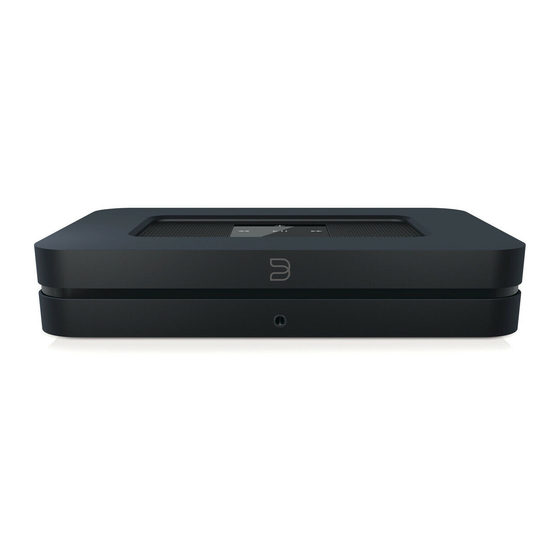
PCB interface assembly instructions for
Bluesound Node 2/2i.
Remove the rear cover by pulling it at the
indicated places.
Remove top two indicated screws.
Lift the upper part of the housing by tilting it
only from the back of the device, until you
hear loud "clicks". Then lift it upwards, being
careful not to break the tapes and cables.
Put the upper case carefully next to it. Do not
disconnect cables, the sockets are secured
with adhesive.
Advertisement
Table of Contents

Related Manuals for Bluesound Node 2


Summary of Contents for Bluesound Node 2
- Page 1 Thank you for purchasing this product. We will be very pleased if you visit our website www.pd-cf.com and leave your review on the product page. PCB interface assembly instructions for Bluesound Node 2/2i. Remove the rear cover by pulling it at the indicated places. Remove top two indicated screws.
- Page 2 Disconnect the small and large socket. You can use longer pliers for this. Remove screws indicated by the arrows. Remove screws on the back panel. After removing factory power supply and stiffening plate, look to the retaining pin. Insert the new interface so that the pin indicated goes into the retaining hole in the module.
- Page 3 Screw the module on, also please install the stiffening plate as shown in the picture. Connect the large JST connector to the socket on the motherboard. Twist the cable harness slightly, being careful not to pull them out of the plug. Mount the back panel - screw the black screw into the indicated hole.
- Page 4 Close the housing by first hooking the indicated latches. If you can't do it, use a little force. Screw the black screws back into place. Install the rear panel cover. After installation should remain: the factory power supply and two silver screws. If the components differ, check the correct assembly.
- Page 5 Additional information: Measurement and regulation. The power supply required by the module should be between 5 and 5.1V. The module has voltage measuring points - described: VCC and GND. They are used to measure voltage under load. They can facilitate fine adjustment of the power supply (if the power supply has such a possibility).
Need help?
Do you have a question about the Node 2 and is the answer not in the manual?
Questions and answers